360 IQ CAP PRESS OPERATOR'S MANUAL - Amaya Sales UK
←
→
Page content transcription
If your browser does not render page correctly, please read the page content below
360 IQ CAP PRESS
                       ™

   OPERATOR’S MANUAL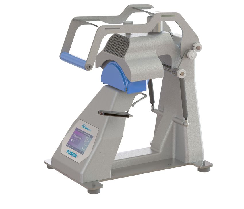
HOTRONIX         ®

                                                                         Safety Instructions
360 IQ CAP PRESS
                                                                 ™

   When using your heat press, basic precautions should always
   be followed, including the following:

   1. Read all instructions.

   2. Use heat press only for its intended use.

   3. To reduce the risk of electric shock, do not immerse the heat press in water or other liquids.

   4. Never pull cord to disconnect from outlet, instead grasp plug and pull to disconnect.

   5. Do not allow cord to touch hot surfaces, allow heat press to cool completely before storing.

   6. Do not operate heat press with a damaged cord or if the equipment has been dropped or damaged.
      To reduce the risk of electric shock, do not disassemble or attempt to repair the heat press. Take it to
      a qualified service person for examination and repair. Incorrect assembly or repair could increase the
      risk of fire, electric shock, or injury to persons when the equipment is used. Power supply cord must
      be disconnected before cleaning or servicing press.

   7. This appliance is not intended for use by persons (including children) with reduced physical, sensory or
      mental capabilities, or lack of experience and knowledge, unless they have been given supervision or
      instruction concerning use of the appliance by a person responsible for their safety.

   8. Close supervision is necessary for any heat press being used by or near children. Do not leave equipment
      unattended while connected.

   9. To avoid burns, do not touch hot metal parts or the heated platen during use.

   10. To reduce the likelihood of circuit overload, do not operate other high voltage equipment on the same circuit.

   11. If an extension cord is necessary, then a 20-amperage rated cord should be used. Cords rated for less
       amperage may overheat. Care should be taken to arrange the cord so that it cannot be pulled or tripped over.

   12. Keep hands clear of the upper heat press platen during lock down as the pressure may cause injury.

   13. Heat press should be placed on a sturdy, suitable stand at least 36"L x 24"W x 29"H.

   14. Work area must be kept clean, tidy and free of obstructions.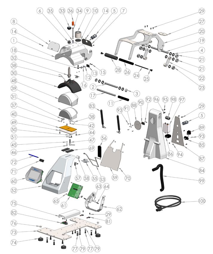
Table Of Contents

                     Safety Instructions 2

                           Machine View 4

                Operating Instructions 5-7
                        Connecting the System    5
                          Start Up/Shut Down     5
                                 Home Screen     6
                              Prepare to Print   7

                    Touch Screen Guide 8-11
                                  Setup Menu     8
                             Password Setup      8
                                 Preset Setup    9
                           Date & Time Setup     10
                                Display Setup    10
                          Auto On & Off Setup    10
                                System Setup     10
                                   Calibration   11
                           Updating Software     11

              Connect to the IQ™ Portal 12

                    Electrical Schematic 13

                Replacement Parts List 14-15

                                   Contact 16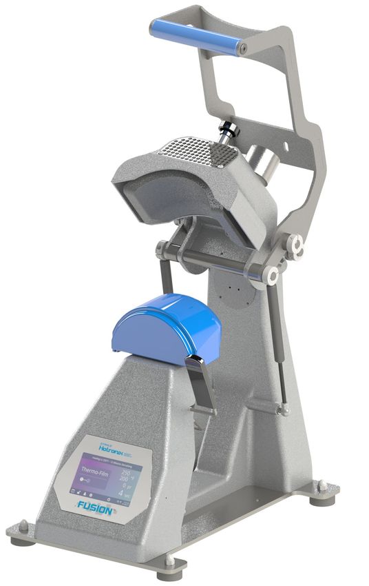
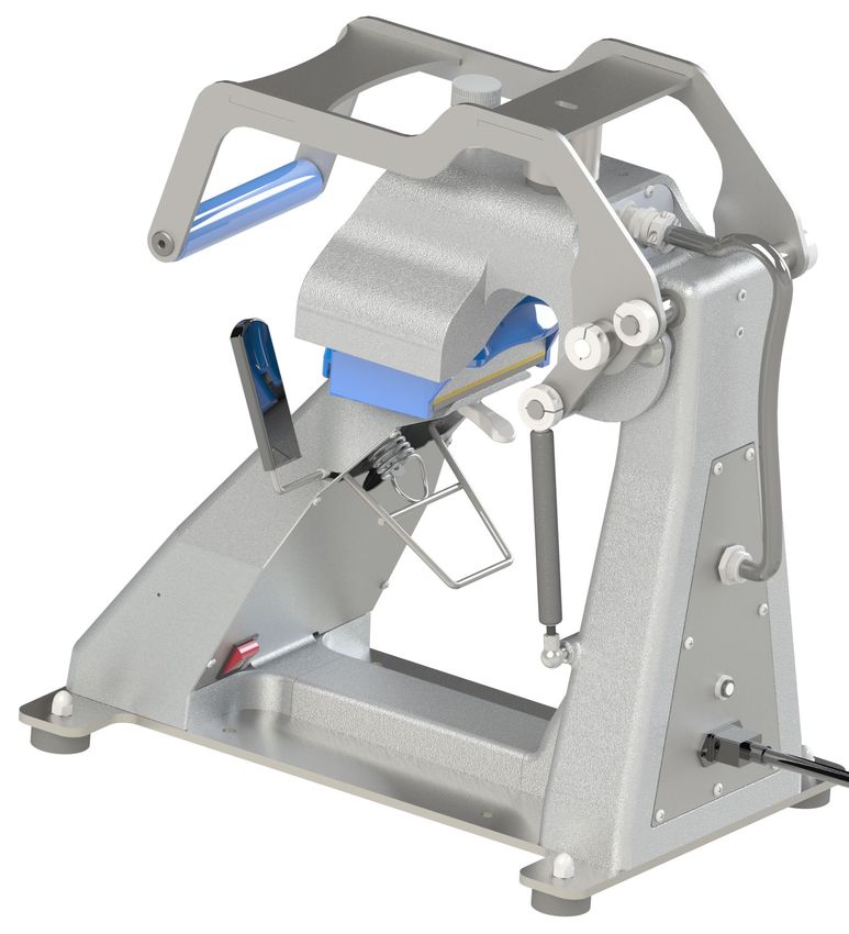
Machine View

                                             Pressure Adjustment Knob
    Lift Handle

    Upper Heater                             Electromagnet

                                                       Platen Alignment Knob   Gas Shock
    Lower Heater with
    Thermal Conductive Pad

    Touch Screen

                                Cap Hold-
                                Down Lever

                             Base
                                    ON/OFF Switch

                                             Cap Hold-Down
                                             Mechanism                                     Circuit Breaker
                                                                                             & IEC Inlet

4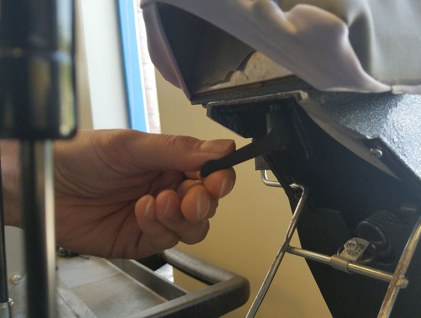
Operating Instructions

Connecting the System
Insert power cord into IEC inlet located on the side of press (1.1).

Connect the power cord into a properly grounded
electrical outlet with a sufficient amperage rating.

To remove a locking power cord (if equipped), depress
the two red buttons while pulling on the plug (1.2).
                                                                                                            1.1

Voltage
120 volt presses require a full 10 amp grounded circuit.
240 volt presses require a full 5 amp grounded circuit.

Extension Cords
If used, extension cords should be as short as possible and
not less than 12 gauge. Heavy duty cords are recommended.
                                                                                                            1.2
Circuits
Circuits that have less than 10 amps, or have other high demand
equipment or appliances (especially more than one heat press)
plugged in, should not be used.
Note: If supply cord is damaged, it must be replaced by the manufacturer,
its service agent, or a similarly qualified person to avoid hazard. Use SJT
type rated 300 V cord for replacement.

Start Up/Shut Down                                                                                          2.1
Locate the packaging bolt on top of press and remove prior to turning
on or operating (2.1).

To start up your heat press: Flip the power switch ON (2.2). A splash screen displaying
the Hotronix® logo and current software version is shown for several seconds.

To turn your heat press off, flip the power switch OFF.

To place your heat press into Standby Mode, touch and release the Power icon on the Home Screen             2.2
(3.2 - following page). In Standby Mode, the heater turns off while the Touch Screen remains on,
displaying an orange background as a warning if the platen is still hot (above 100°F / 38°C).
NOTE: Standby Mode must be used for the Auto On feature to function (10.1).
The Auto On feature will not work if the power switch (2.1) is in the OFF position.

To start up your heat press while in Standby Mode, touch and release the Home icon on the Standby Screen.

                                                                                                                  5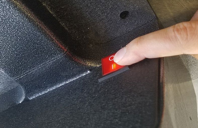
Operating Instructions

    Home Screen
     Status bar provides                                                                      Displays current top
     helpful information                                                                      heater temperature
     regarding heat press.
                                                                                              Displays current bottom
                                                                                              heater temperature
     Touch and edit your
     favorite presets.                                                                        Displays current application
                                                                                              pressure and time.

     Lock the screen
     (Manager-level only)                                                                     IQ™ Portal and WIFI
     to prevent User-level                                      3.1                           connection status.
     operators from
     changing settings.

                       Touch and edit Users to       Touch              Place press in Standby Mode
                       control operator access    Setup Menu.           to take advantage of the
                       level and track press                            scheduled Auto On feature.
                       usage by operator in the
                       IQ™ Portal.

                                                                                              Tap any print parameter
                                                                                              to adjust its target value.
       Displays the selected
       preset. Touch and                                                                      Tap a section of the top
       hold to see application                                                                bar to quickly jump to
       settings.                                                                              the corresponding value

       NOTE: Holding down material
                                                                                              Tap up/down arrows for
       name will display targeted
       application settings. Screen                                                           fine adjustment of target
       displays current temperature,                                                          value
       pressure, and time.

                                                                3.2
       Displays multiple heat                                                                 Tap check mark to
       application preset step.                                                               accept new value or
       Touch the empty circled                                                                X to cancel
       numbers to switch                                              Tap “Off” to disable heater
       between preset steps.

6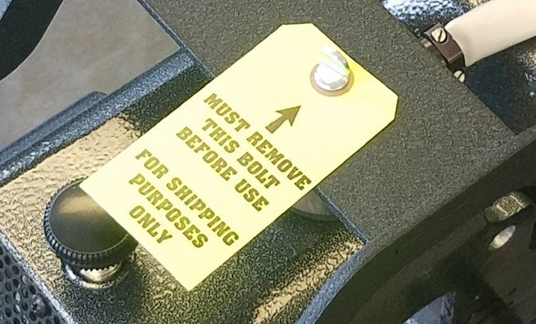
Preparing to Print
Before heat applying, set the target settings for the selected transfer material by:
• Selecting a Preset (7.1), or
• Manually entering target temperature, time and pressure.

Temperature and time are controlled automatically. Pressure must be set manually:
• Position a cap on the lower heater (4.1)
• Lower the cap hold down lever (4.2) to lock it in place
• Enable “Target Temp” option in System Settings (11.1) to prevent the electromagnet
   from locking down until Target Temperature is reached                                             4.1
• Pull lift handle down and observe the pressure reading
• Adjust the pressure by turning the Pressure Adjustment Knob

A visual Pressure Readout is located on the Home Screen. When the handle is locked
into the PRINT position, a pressure number between 0-9 will be displayed.
• 0 = No pressure
• 1 - 3 = Light Pressure
• 4 - 7 = Medium Pressure
• 8 - 9 = Heavy Pressure                                                                             4.2

WARNING: Structural damage caused by excessive pressure is not covered under the limited warranty!

The lower heater alignment can be adjusted by loosening the knob to accomodate
different cap sizes (4.3).

Once your equipment has reached the designated temperature:
• Position the cap and design (4.1)
• Lower the cap hold down lever to lock cap into place (4.2)
                                                                                                     4.3
• Pull lift handle down and begin to heat apply
• The automatic timing process will begin
• The Home Screen will initiate a count down and lift the heat platen into the UP
   position when the print cycle is complete (4.4).

                                                                                                     4.4

                                                                                                           7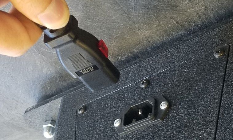
Touch Screen Guide

    Setup Menu
                             Touch the Settings icon on
                             the Home Screen (5.1)
                             to configure your heat press.

                             Managers can access all setup
                             options, while Users can access
                             a limited set (5.2).
                             • Managers default password: M
             5.1                                                       5.2

    Password Setup (Manager Level Only)
                             Touch the User icon on the
                             Home Screen (6.1) or Setup
                             Menu (6.2) to select, add,
                             and edit Users.

                             Touch and edit Managers
                             and Users to configure
             6.1             access to settings (6.3, 6.4).            6.2
                             Heat press reports on the
                             IQ™ Portal can be filtered
                             by User to track individual
                             operator performance.

                             Touch the arrow keys on the
                             taskbar to scroll through a
                             long list of Users (6.5).

             6.3                                                       6.4

             6.5

8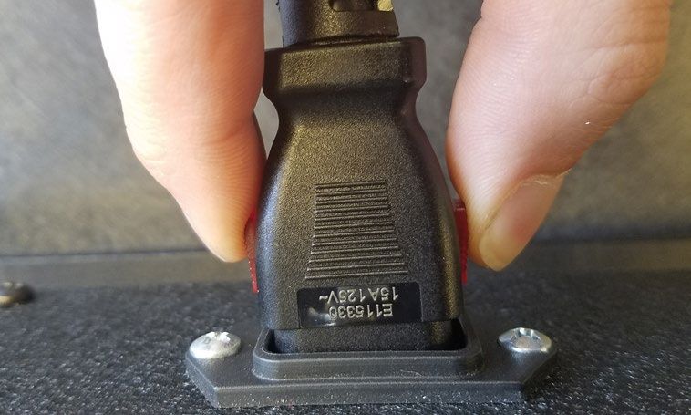
Preset Setup

               Touch the Columns icon (7.1)
               to select from a list of saved
               presets (7.2).

               Touch the arrow keys on the
               taskbar to scroll through a
        7.1                                     7.2
               long list of presets (7.3).

               Touch a preset to select
               a material.

               Touch the Pencil icon (7.4) to
               enter edit mode, then touch
               preset name to edit settings.
               Touch Save to save changes.

               Touch the Plus icon to create
        7.3                                     7.4
               a new preset (7.5).

               Name your preset and
               enter desired temperatures,
               time, and pressure. When
               creating a new preset,
               the current Home Screen
               application settings are
               selected automatically (7.6).

        7.5    Touch the empty circled          7.6
               numbers to set multiple preset
               stages for pretreatment or
               multi-step applications (7.7).

        7.7

                                                      9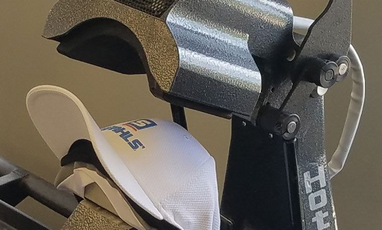
HOTRONIX                     ®

                                                                                               Touch Screen Guide
     360 IQ CAP PRESS
                                                                                           ™

     Date & Time Setup
     Touch the Settings icon on the Home Screen.
     • Touch Date & Time, information displays on right of screen (8.1).
     • Touch up/down arrows to select time zone.
     • Touch Auto to automatically synchronize the heat press clock.
        The heat press must be connected to a WIFI network with
        access to the Internet.
     • Touch Daylight Saving to enable daylight saving mode.                                          8.1
        This option should be enabled during summer.

     Display Setup
     Touch the Settings icon on the Home Screen.
     • Touch Display, information displays on right of screen (9.1).
     • Touch Temperature to switch between F° or C°, then touch
        Check Mark icon on taskbar to save.
                                                                                                       9.1

     Auto On & Off Setup
     Touch the Settings icon on the Home Screen.
     • Touch Auto On/Off, information displays on right of screen (10.1).
     • Touch Enable, then On Hour/Minute and Off Hour/Minute,
        selecting Enter between each setting. Once entered,
        touch Check Mark icon on taskbar to save.
     NOTE: Standby Mode must be used for the Auto On feature to function (3.2).
     The Auto On feature will not work if the power switch (2.1) is in the OFF position.
                                                                                                       10.1

     System Setup (Manager Level Only)
     Touch the Settings icon on the Home Screen.
     • Select System, information displays on right of screen (11.1).
     • Touch Power Save and select time, then touch Check Mark icon
        on taskbar to save. When enabled, your heat press will enter
        Standby Mode if it is not ued for the specified number of hours.
     • Touch Target Temp to prevent the electromagnet from activating
        until target temperature is reached.                                                           11.1

10
Calibration (Manager-Level Only)
Your heat press comes pre-calibrated from the factory. Calibration is only required after sensor or
controller replacement. Pressure is periodically self-calibrated. Incorrect calibration can result in
poor print results or damage to your heat press which is not covered by warranty.
Your heat press has a temperature calibration function (12.1).
• T urn on heat press and heat to 350°F/177°C.
• Measure center of heater with contact thermocouple (not infrared) thermometer.
• T ouch the Settings icon on the Home Screen.
• T ouch Calibration, information displays on right of screen.
• T ouch Temperature 1 for the top heater and adjust Temperature Calibration to
match Target Temperature.
• T ouch Temperature 2 for the bottom heater and adjust Temperature Calibration to
match Target Temperature. Remove rubber cap and adjust 100°F below measured 12.1
temperature for best results.
Your heat press has a pressure calibration function (12.2).
• T ouch the Settings icon on the Home Screen.
• T ouch Calibration, information displays on the right of screen.
• T ouch Pressure and then Calibrate. Wait for the screen to display 2.5V.
• T urn Adjustment Knob counterclockwise (reducing pressure) until stop
• P lace one thin (1/8” 3mm) white pad on mandrell, lower print handle and secure to
electromagnet using 1/4”-20 x 3/4” screw.
• T ap Set Min Point (screen should display reading of approximately 2.5V)
12.2
•U nscrew and raise print handle.
• P lace two additional thick (3/8” 10mm) white pads on mandrell (7/8” 22mm total),
lower print handle and secure to electromagnet using 1/4”-20 x 3/4” screw
• T ap Set Max Point (screen should display reading around 2.1V to 2.4V)
•U nscrew and raise print handle.
Updating Software
Touch the Settings icon on the Home Screen.
•W hen a software update is available, an exclamation point appears after the ver-
sion number in the Setup Menu (5.2).
• T ouch Firmware, information displays on right of screen. An available online 12.3
update displays a cloud icon (12.2).
• T ouch Update File on right of screen, then touch Check Mark icon on taskbar to
start download. A downloaded update displays a memory card icon.
• T ouch Downloaded Update File on right of screen, then touch Check Mark icon on
taskbar to start installation.
NOTE: If a power failure occurs during installation, the heat press will attempt to install the previous
software version.
11Connect to the IQ Portal
™
Create Your Account
•U sing a phone or computer, visit iq.hotronix.com
to create an account (13.1).
• E nter your name, email, and password.
• Click on the confirmation link in the email you receive.
• Y our account has been created.
Register a Heat Press 13.1
• C lick on Manage Heat Presses, then New Heat Press.
• S elect heat press type, enter serial number, and enter a name for
the heat press (optional).
• C lick on Create Heat Press and enter the verification code given.
• On
the heat press Setup Menu, touch WIFI and connect to your WIFI
router or mobile hotspot (13.2).
the heat press Setup Menu, touch the Cloud icon and enter the
• On
verification code displayed in the IQ™ Portal (13.3).
• Y our heat press has been registered.
Create & Assign Users
• C lick on Manage Operators, then New User. 13.2
• E nter a name and select a privilege level. Managers can access all
heat press settings while Users have limited access.
• Click on New User, then Assign Machines in the sidebar.
• Select a machine and click Assign.
• On the heat press Setup Menu, touch the Cloud icon, then Manual Sync (13.4).
• Reporting will show impressions made by the Users.
13.3
13.4
12Electrical Schematic
Upper Heater Upper Heater
120V 50/60Hz 230/240V 50/60Hz TRIAC
RTD Probe RTD Probe
Strain
Frame Gauge
High Temp 14ga
GND
WH 14ga
BK 14ga
RD 20ga
500ºF 500ºF
500W 260ºC 500W 260ºC
Proximity
1,3 Switch
PROX1
Electromagnet
EMAG
HTR2
PROBE2
Lower Heater Lower Heater
120V 50/60Hz 230/240V 50/60Hz
RTD Probe RTD Probe
Frame
High Temp 14ga
GND
500ºF
240W 260ºC 240W
WH 14ga
BK 14ga
500ºF
260ºC
Frame
BK & RD 24ga
GND
ON/OFF
Filter Breaker Switch
L BK 14ga
N WH 14ga
Frame TRIAC 2 WH 14ga
GND BK 14ga
RD 20ga
Frame GND
13Replacement Parts List
# PART# DESCRIPTION QTY. # PART# DESCRIPTION QTY.
1 4-1183 Heater Arm, 360 IQ Hat 1 51 2-1006-46 Washer, 5/16” SS 1
2 2-1055-11 Steel Pin, 1/2” x 5-9/16” 1 52 4-1179 Lower Frame, 360 IQ Hat 1
3 1-1107-1 Hub Cap 1/2” 2 53 4-1180 Cap Hold Down, 360 IQ Hat 1
4 1-1048-3 Washer, 1/2” Nylon 14 54 - Nut, #8-32 Cap Stainless 1
5 - Cord Grip, Sure Clamp Submersible 2 55 1-1073 Spring 1
6 - Threaded Insert, 1”-8 to 5/8”-11 1 56 - Round Rubber Grip, 3/4” x 4-1/2” 1
7 - Heater Arm Panel, Rear 1 57 - Loop Clamp, 3/8” Galv Steel 1
8 - Heater Arm Panel, Front 1 58 - Cable Holder, Nylon Self-Adhesive 1
9 1-1945-1 Electromagnet 1 59 - Lower Support Cover, 360 IQ Hat 1
10 1-2133 Silicone Pad, 5/16” ID x 1-3/4” OD x 1/4” T 1 60 1-2463 Fusion IQ Controller 1
11 - PVC Spacer, 1/2” x 4-3/8” 1 61 1-2463-P Fusion IQ Power Board 1
12 - Standoff, #6-32, 3/8” OD, 3/8” Long 2 62 1-2473 Fusion IQ Power Bracket 1
13 1-1219 Proximity Magnet 1 63 1-2474 Fusion IQ Latch 2
14 3-1011-10 Screw, Machine #8-32 x 1/4” 7 64 1-2485 Spring, 1/4” x 1”, 1.7lbs/in 2
15 - Screw, #6-32 x 3/8”, Stainless 4 65 3-1011-235 Screw, #6 x 1/2” for Plastic 4
16 - Lockwasher, #6 External-Tooth Stainless 2 66 - Spacer, 1/4” x 1/4” Slotted 2
17 - Steel Pin, 1/2” x 8-3/32” 1 67 - Washer, #8 Stainless 2
18 3-1011-233 Screw, Shoulder 5/16” x 1/2” 1 68 - Screw, #8-32 x 1/2” Stainless 1
19 - Steel Pin, 1/2” x 7-9/16” 1 69 - Silicone Pad, 1/4” x 1” Self-Adhesive 2
20 - Handle Weldment, 360 IQ Hat 1 70 3-1011-25 Screw, Machine #6-32 x 1/4” 6
21 - Shaft Collar, 1/2” One-Piece Clamp-On 4 71 1-2386 Touchscreen Stylus Holder 1
22 - Link Weldment, 360 IQ Hat 2 72 1-2385 Touchscreen Stylus 1
23 - Shaft Collar, 1/2” One-Piece (Modified) 2 73 - Base Plate, 360 IQ Hat 1
24 - Threaded Rod, 1/4”-20 x 6” 1 74 1-2575 Rubber Foot 4
25 2-1006-2 JCN - NUT 2 75 4-1181 Base Channel, 360 IQ Hat 1
26 - PVC Spacer 1” x 6” 1 76 - Nut, M8x1.25 Cap 4
27 - Magnet Plate, 360 IQ Hat 1 77 3-1011-243 Screw, Socket Head 1/4”-20 x 3/4” 8
28 1-1540 Foam Grip, Black 1 78 3-1011-100 Screw, Socket Head 5/16”-18 x 3/4” 8
29 3-1011-127 Screw, Machine #8-32 x 3/8” Black Oxide 15 79 2-1006-44 Washer, Split Lock 1/4” 8
30 3-1386 Heater, Upper, 360 IQ Hat, 500W 1 80 2-1006-86 Washer, Split Lock 5/16” 8
31 1-2076 Thermostat Disc 2 81 1-1059 TRIAC 2
32 2-2147 Adjustment Spindle, Cap 1 82 - TRIAC Driver Board 1
33 1-1095 Knob, Black Plastic 3/8”-16 1 83 - Gas Spring 20lbs 2
34 3-1011-238 Bolt, Hex Head 5/16-18 x 3-1/2” 1 84 4-1182 Column, 360 IQ Hat 1
35 1-2163 Compression Spring 1 85 1-1759 Power Inlet 1
36 - Silicone Cap, 1/2” x 1” 1 86 1-1331 Circuit Breaker 20A (STX XF XRF) 1
37 3-1011-98 Screw, SS Sheet Metal #4 X 1/4” 4 87 - Column Back Plate, 360 IQ Hat 1
38 1-1272-1 Temperature Probe 2 88 - Proxy Plate, 360 IQ Hat 1
39 3-1385 Heater, Lower, 360 IQ Hat 240W 1 89 1-2087 Power Switch 1
40 - Insulation, 1/8” x 2.75” x 5.75” 1 90 1-1211 Proximity Switch 1
41 2-1006-101 Washer, #6 Oversized 1 91 3-1011-22 Screw, Machine #4-40 x 3/8” 2
42 - Screw, #4-40 x 3/8” Stainless 1 92 2-1006-51 Nut, #4-40 with Tooth Washer 2
43 - Weld Nut, 1/4”-20 Steel 1 93 3-1011-19 Screw, Machine #6-32 x 1/2” 6
44 - Screw, #8-32 x 1/2” Stainless 5 94 2-1006-50 Nut, #6-32 Hex with Lockwasher 2
45 - Lock Washer, #8 External Tooth 1 95 - Set Screw, 5/16”-18 x 1/2” 1
46 - Dowel Pin, 1/4” x 3/4” Pull-Out 1 96 - Set Screw, 5/16”-18 x 3/4” 1
47 - Clamp Handle, 1/4”-20 x 1-3/4” Long 1 97 - Filter, Schaffner FN2090-6-06 1
48 1-2592 Thermal Snap Cap 1 98 - Ferrite Core 461167281 1
49 - Lower Heater Plate, 360 IQ Hat 1 99 - Conduit 1
50 - Spacer, Steel, 1/2” OD, 1/8” LG, 1/4” Screw 1 100 2-1671 120V Locking Power Cord 1
14Parts Location Guide
15www.amayauk.com | 02392 590281 | sales@amayauk.com
You can also read