3D Production Edit Work Flow at the London 2012 Olympics
←
→
Page content transcription
If your browser does not render page correctly, please read the page content below
SMPTE Meeting Presentation

                3D Production Edit Work Flow at the London 2012
                                   Olympics

James DeFilippis, MSEE, PE
          Broadcast Engineering Consultant, LA, CA, JimDTV12@gmail.com

                                              Written for presentation at the
                                     2012 SMPTE Fall Conference in Los Angeles

Abstract. For the first time the Olympics were telecast in 3D. In the past, some 3D coverage was
available on a closed circuit basis of limited events. The London Olympics 3D Channel covered
multiple sports, both live and ENG coverage, and provided a full up 3D channel of over 275 hours of
3D programming. Part of the Olympic 3D Channel every day was a (1) hour Summary program,
presenting the best of the live 3D Coverage as well as the EFP single camera coverage captured
that day.
This is the first time a 3D daily program was attempted, using a hybrid edit work flow. The paper will
discuss the work flow, including the capture of the ENG footage using the Panasonic P2 3D camera,
EVS Servers and AVID Media Composer editing. Additionally the challenge of quick turn around and
the QC process to insure the materials were ‘stereo’ correct. The paper will cover the specific issues
of what worked and what did not.
Keywords. Leave the word "Keywords." 3D, Stereoscopy, Sports, Olympics, Editing, File Based
Workflow

The authors are solely responsible for the content of this technical presentation. The technical presentation does not necessarily reflect the
official position of the Society of Motion Picture and Television Engineers (SMPTE), and its printing and distribution does not constitute an
endorsement of views which may be expressed. This technical presentation is subject to a formal peer-review process by the SMPTE
Board of Editors, upon completion of the conference. Citation of this work should state that it is a SMPTE meeting paper. EXAMPLE:
Author's Last Name, Initials. 2011. Title of Presentation, Meeting name and location.: SMPTE. For information about securing permission
to reprint or reproduce a technical presentation, please contact SMPTE at jwelch@smpte.org or 914-761-1100 (3 Barker Ave., White
Plains, NY 10601).

                         Copyright © 2012 Society of Motion Picture and Television Engineers. All rights reserved.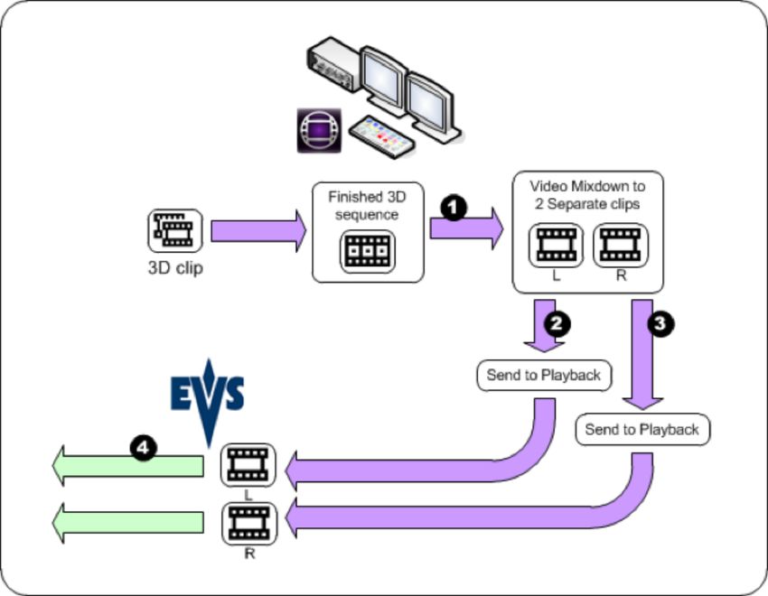
Introduction
OBS was asked to provide a full 3D service for the 2012 London Olympics. Planning started
approximately 9 months prior to the Opening Ceremonies. Participating Rights Holders
included NBCU, BBC, Eurovision, Japan Pool, Sky Italia, Ch9/FOXTEL, and others. Panasonic
provided support including specialized 3D stereoscopic production equipment, specifically
professional 3D monitors and the first P2 camcorder capable of capturing stereoscopic 3D
images.
The OBS 3D Project organized (3) 3D OB Vans to produce full up stereo TV productions at (4)
Venues: Olympic stadium (Opening, Athletics, Closing), Lee Valley (Canoe Slalom), Aquatics
(Swimming, Diving, Sync Swimming), and North Greenwich Arena (Gymnastics, Basketball).
The three OB vans suppliers were; Telegenics (Stadium and Lee Valley), Alfacam (NGA), EMG
(AQU). These venue 3D productions would account for the majority of the 3D programming
including the most popular Olympic events.
The 3D ENG coverage was possible due to the development by Panasonic of the AG-3DP1 P2
Camcorder, which is an ‘all in one’ 3D lens/camera system that can record on P2 memory
cards. The 3D Project provided for (7) ENG crews which consisted of a Field Producer,
Cameraman and Camera Assist (student trainee). (6) of these crews covered the following
sports:
      Archery, Judo, Wrestling, Boxing, Taekwondo, Fencing, Weightlifting,
      Equestrian, Hockey, Water Polo, Tennis, Table Tennis, Badminton,
      Volleyball, Beach Volleyball, Track Cycling, BMX, and Handball.
The ENG materials were edited in the field and transmitted to the IBC via dedicated IP
connections at each venue, located within the Venue TOC (Television Operations Center).
The 3D Project organized a full up Summaries production team including (4) Summaries
Producers, a Senior Summaries Producer, (2) Media Managers, (2) Voice Over Commentators
and (4) Editors. The role of the Summaries production was to create a daily (1) hour 3D
program with the ENG coverage and the highlights from the live 3D productions.
The 7th ENG team was organized to provide ‘behind the scenes’ materials on the making of the
Olympic 3D coverage documentary.

3D IBC Cabins
The Olympic 3D project was managed from the 3D Cabins outside the IBC, with venue specific
production handled by each Production team and the OB Van vendor. The ENG coverage was
delivered daily via IP file transfer from the (6) crews to be incorporated into the Summary show
that night. The 3D Channel, distributed to the Right’s Holders at the IBC as well as one of the
channels on the MDS Satellite delivery from the IBC, was on air from approx 8am until 1am or
2am the next day
Upstairs, there were (4) Summaries Producers and a Senior Summaries Producer, responsible
for the editorial direction of the Summary packages. Assisting the Summary Producers and
editors were the (2) Media Managers. The Media Manager’s role was to manage the files on
the EVS Servers, check ENG files as they came in, QC the Summary Packages, clip recordings
needed for editorial or for the final Summary program. (4) 3D Edit Rooms were equipped with
an AVID Media Composer system (V6) along with a Nitrous hardware i/o unit. The editors had
a 25” LCD 3D monitor as well as an IP Director to search and transfer clips to the AVID from the
EVS Server. Finally each edit room had a Voice Over booth for commentary and announce

                                                                                                           2
               Copyright © 2012 Society of Motion Picture and Television Engineers. All rights reserved.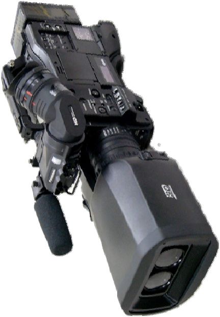
recording. Later a Graphic station was added outside the Edit suites to be able to pull start list
and result graphics for use in the Summary packages.

ENG Coverage
As part of the Olympic 3D Project there were (7) ENG crews that were equipped with the
Panasonic AG-3DP1 Stereoscopic P2 Camcorder, a P2 USB Card Reader, laptop PC with EVS
Xedio Editing and Transfer software, stereo microphone, tripod, batteries, battery charger,
Panasonic BT-LH910G 9” LCD monitor with 3D tools, (6) 64GB P2 cards, remote convergence
controller, and Anton Bauer Ultralight 2-10 ENG light.
The Stereoscopic 3D coverage was determined by the capabilities of the Panasonic AG-3DP1
camcorder. This camera is the second generation Panasonic 3D camcorder system and
included several improvements: shorter interaxial distance (58mm), extended zoom
convergence ranges (near, normal and extra), and 6 point vertical disparity correction. The
camera processing includes 3D assist functions such as Parallax Alert, Convergence marking in
Green, and Mix mode monitoring. The basic imaging system is based on 1/3” CMOS sensors
with coupled stereoscopic lens system. However the camera viewfinders are 2D only; thus no
ability to view the recorded clips in 3D.

                               Figure 1. File transfer into EVS XT3 Server

The P2 cards were transferred to the 3D EVS Server via the Xedio laptop editing system and
dedicated IP connections from the venue TOC’s to the IBC. The transfer and edit process was
a two step process; first the editor would ingest the Left Eye clips and make a ‘story board’ of
the selected clips. The Left Eye story board was marked as ‘ -LE’ and then uploaded to the
local HDD as well as an external HDD. The second step was to eject the Left Eye P2 card and
insert the Right Eye card. The story board would re-populate with the RE version of the clips.
This story board would be renamed as ‘-RE’ and then uploaded to the local HDD as well as the
external HDD. Finally, the uploaded -LE and -RE clips were transferred to the EVS Xstore
system in the 3D cabin into a file folder labelled as to the ENG Crew number (ie ENG01). Using
the IP Director in the Edit Suite, these ‘storyboard’ clips could be transferred into the AVID 3D
Media Composer.
The challenge to this work flow was that the Xedio did not recognize if the correct card (LE or
RE) was inserted in the correct order. This did cause some materials to be transferred in the
with the wrong association of LE/RE or double fed the same eye.

                                                                                                            3
                Copyright © 2012 Society of Motion Picture and Television Engineers. All rights reserved.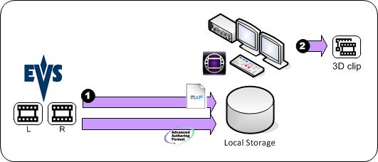
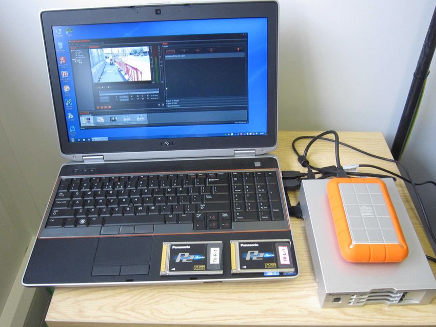
Figure 2. Xedio Field Edit Package

While the P2 camcorder would not playback 3D clips when the cards were not inserted into the
correct slot, the camcorder would allow recording of new clips with the cards in the incorrect
slots. To help prevent this, camera bars were recorded on each pair of cards. The operational
procedure required the camera operator to ‘play back’ bars as a check that the cards were in
the correct slot.

3D Editing Process
The organization of the 3D editing was a collaboration between AVID and EVS. AVID proposed
to use the latest Media Composer software (v6.0) which has stereoscopic 3D tools (based on
their Multi-cam application). EVS provided the servers for both live recording and as a ‘SAN’ for
the AVID edit machines. The AVID Media Composer software used an HP Z800 multi-core
processor with 8G of RAM (later upgraded to 16G) with a local 5TB raid array connected via
fibre channel. Along with each HP Z800 was an AVID Nitrous Interface unit providing dual
HDSDI input and output ports as well as providing for genlock synchronization. Each machine
was networked with the EVS servers over a gigE network. There were (3) EVS XT3 servers
connected via a HD-SDTI network. Each server had (6) HD-SDI channels, configured in pairs.
In the first two servers, the configuration was (2) input pairs and (1) output pair; the third server
had (1) input pair and (2) output pairs.

Each 3D Edit suite was outfitted with a Panasonic BT-3DL2550 25” passive LCD 3D monitor for
quality control evaluation, a small audio voice over (off tube type) room with microphone, 2D
display and headphones. In addition, each Edit suite had an EVS IP Director for use by a
producer to make shot selections from materials in the EVS servers and transfer them to the
AVID MC.

File Transfer Processes
The 3D edit file work flow depended on the sourcing of the 3D materials. There were three
sources: Live recording on the EVS XT servers, ENG clips transferred from the field to the
XStore drives, or a transfer from the 2D EVS servers. In all cases the raw clips were transferred
into the AVID Media Composer workstation through the use of EVS IP Director system. The IP
DIrector is a software based media manager that can browse the materials available on the
EVS Servers, create sub-clips, and initiate a transfer into the AVID Media composer (see Fig.
3).

                                                                                                            4
                Copyright © 2012 Society of Motion Picture and Television Engineers. All rights reserved.
Figure 3. File transfer into AVID Media Composer
In the case of 3D clips, there were two files transferred, a Left Eye (LE) and a Right Eye (RE)
file. These files would be identified by the file name having either a ‘-00’ (LE) or a ‘-01’ (RE)
appended to the name. In the case of the 2D clips, these would be handled as a mono pair
source and then adjusted in the Media Composer by ‘side slipping’ (H offset) of the images to
create a depth plane.
Once these clips were transferred to a bin inside the Media Composer, the Editor would initiate
a series of steps to convert the individual ‘eyes’ into a AVID S3D clip.
The AVID Media Composer 6 can then edit the clip as a 3D/Stereo asset. There are many tools
in MC 6 to adjust, convert and manipulate the 3D imagery. There are not analysis or QC tools;
we did investigate a few such tools as plug-ins or stand alone software packages but did not
find one that would integrate into an AVID environment.
Figure 4. File transfer into EVS XT3 Server
When the 3D edit package is finished and QC’d, the editor would initiate a series of steps to
convert the S3D file into separate LE and RE files (see Fig. 4). This is a render type process
that took approximately real time to create both eyes. After these LE/RE files are rendered, the
editor would append the ‘-00’ and ‘-01’ filename tags and then initiate a transfer to the EVS XT3
server using Avid Transfer manager. This transfer process would take over 2x real time to
5
Copyright © 2012 Society of Motion Picture and Television Engineers. All rights reserved.move the files into the EVS XT 3, mainly due to the large size (effectively 200Mb/s), the 1GB/s
network speed, and other IP traffic including the IP Director activities.
Once the files are transferred into the EVS XT3 server, the EVS operator would have to
associate these files as as a pair by ‘grouping’ the files. If the files were not associated correctly
(grouped) or the tags were omitted or wrong, the 3D files would not play out correctly.
Workflow Issues
While the 3D work flow did eventually work, there were many issues that caused bottlenecks,
confusion and mistakes. However the limitations of both hardware and software, and the desire
to not transcode any 2D material that was available as AVC I 100Mb/s, did limit options to
improve the work flow. The alternate work flow was to ‘playout’ the 3D finished segments and
record in real time. While this provided relief from the 2:1 transfer time, it tied up the Edit Suite
and did not enhance the work flow.
Much time and effort was devoted to test this work flow and make improvements. While we did
find many problems and solve them, ultimately the work flow was no optimum. Here are some
of the observations regarding the AVID/EVS 3D workflow:
• Slow transfer out of the AVID Media Composer. Given the limited resources of the AVID
stand alone machines, the effective overall transfer rate was twice as long as real time (a 5
min clip would take 10min). However in addition there was a ‘render time’ penalty (1:1 with
real time) to create separate LE/RE files from the AVID 3D project. File transfers would slow
down due to bandwidth bottlenecks into the EVS servers, which was somewhat ameliorated
when the XT3-3 was dedicated as the primary transfer server.
• Difficulties and confusion regarding the ingest of files from EVS into AVID as well as the
transfer of the files out of the AVID to EVS. The marking of the files as to Left Eye or Right
Eye was a matter of convention in the file name. Thus a mistake in the file name or a mis-
interpretation led to mistakes. The EVS Servers used a convention of -00 for LE and -01 for
RE while the AVID file naming relied more on the Editor using notation of LE or RE. The
lack of automatic marking of the files with the correct eye caused much of the major
mistakes (either LE/RE reversal or in duplicating one eye into both files thus creating a
mono version of the clip).
• Bandwidth constraints. Balancing the bandwidth usage between the Edit Rooms, the IP
Directors (5 in Editorial, 4 in Archive), and the Playout Channels (2) was difficult at first and
caused many delays and in one case caused a playout issue .
• AVID Media Composer 6 had many issues related to both the new 3D tool set and work
flow, as well due to the lack of maturity of the software (release 6 came out around NAB
2012). There was an ongoing issue related to 16bit vs. 24bit audio. The AVID’s were set up
for 24bit, the EVS servers 16bit. This caused some software crashes. This was resolved by
converting all the AVIDs to 16 bit audio bit depth.
• Lack of uniformity of setup in each room. While the AVID personnel tried to instill ‘best
practices’, the editors would choose their own settings, which led to problems and lack of
conformity between the output products.
• Lack of QC/Lack of 3D experience. The assumption with this work flow is that the editors
would 100% QC their final packages before transfer. While we had the lead Stereographer
provide a quick tutorial on 3D, focused on identification of ‘bad’ 3D, this training was not
sufficient for the editors to be able to identify and correct the 3D errors. In general, having
someone check their own work is not a sure way to get good results. We set up an ‘ad-hoc’
6
Copyright © 2012 Society of Motion Picture and Television Engineers. All rights reserved.QC station in the Editorial Office next the the Edit Suites and provided the Media Managers
with some tools to check the 3D edit packages. This process did catch the severe 3D errors
but the QC station lacked tools to check tor more subtle problems. We also employed the
downstairs 3D QC (Stereographer and CDX Op) to provide final QC and feed back.
Unfortunately due to time constraints, only the most egregious errors could be dealt with and
thus materials with significant errors did air. It was difficult to coordinate the QC process
and despite passing notes, we would find the same defective clips coming back in a
package after noting that the line recording had the issue.
• Audio. First there were problems of incorrect audio track assignments on the edit package
output files. The editor had to duplicate the International Stereo mix onto tracks 1 and 2 as
well as 3 and 4. Because the EVS server did not have the ability to modify or duplicate
audio tracks, it was important for the edited packages to come with the correct audio
assignments. Second problem was the audio levels, inconsistent at first, with levels either
too high or low and no balance between the International Sound and the Commentary/Voice
Over levels. We established the correct channel assignments as well as ensuring that the
International Stereo effects would be 2-4dB below the OBS standard. (-18dBFS) so as to
allow the VO/Commentary to be mixed in correctly with the VO levels averaging -18dBFS.
• Video. Another issue was video levels. When we had video issues, they editors were not
able to correct these either due to time constraints or a lack of tools. The Edit Rooms were
not outfitted with external video WFM/V-Scopes.
• Lack of visibility of transfer status. The transfer of files and the status of the transfer was not
available globally. In the Edit Suites, transfer into the AVID could be monitored using the
EVS IP director, but not within the AVID MC. Likewise, transfers out of the AVID could only
be monitored within that specific MC PC. This caused confusion regarding what clips were
ready and which were pending. Worse case was if the EVS Operator tried to playout a clip
being transferred and potentially underflowing the transfer buffer.
3D QC, Artifacts and Defects
The role of the Stereographer in the 3D Technical QC position was envisioned to be the final
control point to insure proper stereo imaging mainly of the live venue feeds. The role expanded
to include the QC of edit packages, working with the editors on fixes, instructing all the 3D cabin
personnel on proper stereo imaging as well as the common errors encountered. The main tools
used by Stereographer were the Panasonic 25” LCD 3D monitor and 3ality SIP. The SIP was
used in ‘difference’ mode with grid chart to calibrate visually the depth budget as well as provide
metrics such as height mis-match, zoom mis-match, rotational mis-matched, keystone error,
LE/RE image synchronization, video gain error, and color gamut error.
While the Stereographer was key to the 3D, proper 3D requires that all aspects of the video be
optimum; thus the other position in the Technical QC station, the CDX operator, was just a
important to insure the video basics (levels, timing, synchronization, and color) of the 3D signals
are correct.
The main problems encountered on the incoming materials were:
• Left Eye/Right Eye reversal. Mostly occured in the ENG and edit packages, although early
venue productions, some camera and equipment errors caused this to happen. Easy to
correct.
• Left Eye/Right Eye non-synchronous. This problem showed up in two ways, a fixed offset
of number of frames delay and a ‘drifting’ problem. Causes could be a stereo frame sync
7
Copyright © 2012 Society of Motion Picture and Television Engineers. All rights reserved.that was not setup correctly or equipment that lost lock. This could occur with the EVS
Server playout if the clips had not been properly ganged or had been stopped and not
rewound to the head of the clip. The fixed delay issue was simple to correct; the variable
drift could not be corrected but the cause identified and remedied.
• Vertical displacement. If the one eye was off by a line or so of video, then the two eyes
images would be displaced vertically (height). Correctable.
• Left Eye/Right Eye focus mismatch. A lens problem, could occur during a change in focal
length (zooming) or mis-calibrated focus servos. Is not correctable so the source of the
problem has to be found and remedied.
• Left Eye/Right Eye zoom mismatch. A lens or servo problem. Can be corrected somewhat
(digital zoom out/in of the LE or RE).
• Left Eye/Right Eye Luma or chroma mismatch. Camera issue. Can be corrected. Note
that even errors as much as 0.5% can be detected by the viewer. It was difficult to obtain
gamma matching between two cameras and virtually impossible to get the video clip/knee
circuits to match.
• Edge or Window violations. When an object is near the left or right side of the image
‘window’ and thus the LE and RE images are not symmetrical. Cannot be fixed so need to
cut around the issue. Caused mainly by people and equipment moving into the field of view
or camera operator not protecting the shot when panning or zooming.
• Out of bounds convergence/parallax. OBS 3D specification was a maximum of -1% (in
front of the screen) and +4% (behind the screen). Correctable to some degree by ‘side
slipping’ the Left Eye/Right Eye signals if there was margin to do so (ie the total depth was
less than the maximium depth budget of 5%).
• Flicker. This is caused if the two camera shutters are not synchronized and the camera is
pointed toward a bright light source or there is a strong reflection in the image. Main cause
are CMOS sensors with rolling shutters that are not synchronized. Not correctable. Avoid
shooting into lights with this type of camera.
• Lens flare/reflections. Lens flare for each eye is different due to the optical pathway
difference, especially if the light source is not in the center of the image. Cannot be
corrected. Further issues occur with Mirror Rigs due to internal reflections of the mirror.
This can be corrected with a 1/4 wave optical filter.
Final Thoughts
The 3D editing workflow was quite a challenge and absorbed much of the 3D prep time. There
were many reasons for this but core to the difficulties was the use of AVC I encoding. However
for 3D this proved to be a large burden, causing the AVID MC Editing stations to be operating at
their limits and making file transfers slower. A better choice might have been to use DVC Pro
100. A complete, dedicated 3D QC station for edit packages would have been very helpful.
Built in 3D analysis and auto-correction software is a must to improve the quality while reducing
the turn around time. The key take-away is that what the London Olympic 3D Project attempted
was a to produce a ‘sports news magazine’ show, something done in 2D every day, in 3D. 3D
has to be made workable in this tight turnaround type of production, for 3D to become
mainstream.
8
Copyright © 2012 Society of Motion Picture and Television Engineers. All rights reserved.Acknowledgements
I would like to thank the following people from OBS: Manolo Romero, Sotoris Salamouris,
Isidoro Moreno, Guillermo Jimenez, Ava Garcia, Adrian Vega, Juan Manual Suarez, Nuno
Duarte, Dennis Baxter
The 3D Project Team: Enrique Criado, Rob Gill, Richard Hingley, Neil MacDonald, Nick Mills,
Andy Roberts, Sophia Sanchez, Jonny Slack, Brian Cutts, Matt Aitchison, and Francisco
Carrasco, Jack McShane, Giovanni Laniando, Mark Wallace, Kristin Mason and Eric Green for
all their help and assistance.
The AVID support team: Marc Clouet, Adrian Davies, Jody, Neil Tindal, and Matija Tonejc
The EVS support team: Alex Redfern, Paul, and Josh Symons
The Panasonic support team: Masato Hachiman, Koji Yamamoto, and Noriaki Wada
9
Copyright © 2012 Society of Motion Picture and Television Engineers. All rights reserved.You can also read