A large octupole magnetic trap for research with atomic hydrogen
←
→
Page content transcription
If your browser does not render page correctly, please read the page content below
A large octupole magnetic trap for research with atomic hydrogen
                                                            J. Ahokas,1 A. Semakin,1 J. Järvinen,1 O. Hanski,1 A. Laptiyenko,1 V. Dvornichenko,1 K. Salonen,1 Z. Burkley,2
                                                            P. Crivelli,2 A. Golovizin,3 V. Nesvizhevsky,4 F. Nez,5 P. Yzombard,5 E. Widmann,6 and S. Vasiliev1
                                                            1) Wihuri   Physical Laboratory, Department of Physics and Astronomy, University of Turku, 20014 Turku,
                                                            Finland
                                                            2) ETH, Zurich, Institute for Particle Physics and Astrophysics, 8093 Zurich, Switzerland
                                                            3) Lebedev Institute, 53 Leninsky pr., Moscow, Russia, Ru-119333
                                                            4) Institut Max von Laue -ÂŰ Paul Langevin, 71 avenue des Martyrs, Grenoble, France,
                                                            F-38042
arXiv:2108.09123v1 [physics.atom-ph] 20 Aug 2021

                                                            5) Laboratoire Kastler Brossel, Sorbonne Université, CNRS, ENS-PSL Université, Collège de France, 75252, Paris,
                                                            France
                                                            6) Stefan Meyer Institute for Subatomic Physics, Austrian Academy of Sciences, Kegelgasse 27, A-1030 Wien,
                                                            Austria
                                                            (*Electronic mail: servas@utu.fi.)
                                                            (Dated: 23 August 2021)
                                                            We describe the design and performance of a large magnetic trap for storing and cooling of atomic hydrogen (H). The
                                                            trap operates in the vacuum space of a dilution refrigerator at a temperature of 1.5 K. Aiming at a large volume of the
                                                            trap we implemented the octupole configuration of linear currents (Ioffe bars) for the radial confinement, combined
                                                            with two axial pinch coils and a 3 T solenoid for the cryogenic H dissociator. The octupole magnet consists of eight
                                                            race-track segments which are compressed towards each other with magnetic forces. This provides a mechanically
                                                            stable and robust construction with a possibility of replacement or repair of each segment. A maximum trap depth of
                                                            0.54 K (0.8 T) was reached, corresponding to an effective volume of 0.5 liters for hydrogen gas at 50 mK. This is an
                                                            order of magnitude larger than ever used for trapping atoms.
                                                            Keywords: Magnetic trapping,superconductive magnets, atomic hydrogen, cold atoms

                                                   I.   INTRODUCTION                                                    amount of antihydrogen available.

                                                                                                                           In this article, we describe the construction and test results
                                                      The invention of magnetic traps provided a broad range of         of a large and relatively simple IPT designed for studies of
                                                   possibilities for studies of neutrons and atoms at ultra-low en-     ultra-cold atomic hydrogen by the GRASIAN collaboration14,
                                                   ergies without physically contacting material walls. These           the main goal of which is to observe and study gravitational
                                                   techniques combined with evaporative or laser cooling al-            quantum states (GQS) of H above the surface of superfluid
                                                   lowed reaching quantum degeneracy and boosted the research           helium15. We project formation of BEC in the potential well
                                                   of cold atoms, including precision spectroscopy and metrol-          provided by gravity and the quantum reflection from the su-
                                                   ogy. Several configurations of magnetic traps have been pro-         perfluid helium surface, as well as precision spectroscopy of
                                                   posed in the middle of last century for trapping atoms1,2 and        the ultra-cold H gas. A large volume of the trap is important
                                                   neutrons3. Pritchard4 emphasized the possibility of using 3D         for the storage of a low density gas of H atoms at temperatures
                                                   magnetic trapping for precision spectroscopy of neutral par-         below 1 mK because it will increase the life-time of the sam-
                                                   ticles. He proposed to use an electric current configuration         ple limited by second order relaxation due to interatomic col-
                                                   introduced by Ioffe5 for the stabilization of plasma: a set of       lisions. Another specific feature of experiments with atomic
                                                   linear conductors parallel to the trap axis (Ioffe-bars) com-        hydrogen is the necessity of a superfluid helium film lining
                                                   bined with two pinch solenoids for closing the magnetic bot-         the walls of the confinement cell, cooled to ∼100 mK by a
                                                   tle in the axial direction. Since then the traps of this type are    dilution refrigerator. Since dry dilution refrigerators with a
                                                   called Ioffe-Pritchard traps (IPT) and are widely used in ex-        common vacuum space are becoming standard equipment for
                                                   periments. The proposal of Hess6 to cool atomic hydrogen by          desktop experiments, we designed our IPT for operation in
                                                   evaporating the most energetic atoms from an IPT promoted            such conditions. We found nearly equal performance of the
                                                   the quest for Bose Einstein Condensation (BEC) which was             trap in the bath of liquid helium at 4.2 K and in vacuum being
                                                   finally reached in 1995 for 87 Rb7,8 and three years later for       cooled by the 1 K pot of the dilution refrigerator. We reached
                                                   atomic hydrogen9.                                                    the maximum trap depth of 0.8 T, similar to that in large scale
                                                      IPTs developed for research with atomic hydrogen10 and            installations12,13 , while having nearly the largest effective vol-
                                                   neutrons11 aimed at large trap depths and volumes in order           ume: 0.5 liters at the gas temperature of T = 50 mK. Our trap
                                                   to maximize the number of trapped particles. More recently,          has a modular construction with an octupole magnet for ra-
                                                   progress in the production of slow anti-protons at CERN stim-        dial confinement, two axial pinch coils and a 3 T solenoid for
                                                   ulated the development of large-size traps for antihydrogen,         the hydrogen dissociator. All coils, including the 8 race-track
                                                   which were developed by ALPHA12 and ATRAP13 collabo-                 modules of the octupole magnet, are assembled so that each
                                                   rations. The requirements of a large trapping field and vol-         coil may be easily replaced in case of a possible damage, e.g.
                                                   ume are even more important there because of a very limited          caused by a catastrophic quench.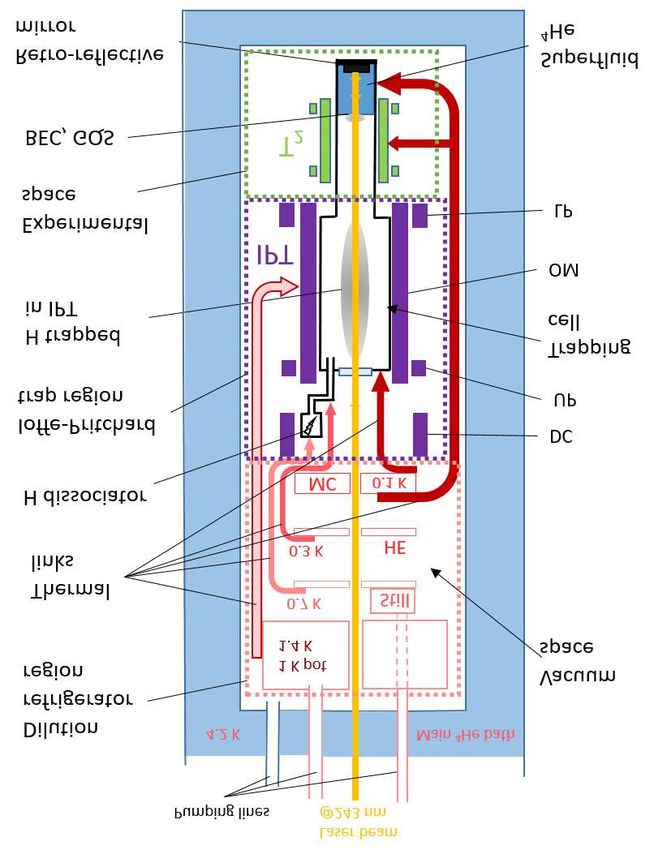
2

   We discuss below the choice of the magnetic field configu-
ration, trap design, details of construction, manufacturing pro-
cedure, and test results in a liquid helium bath as well as in the
vacuum of the dilution refrigerator. We also discuss possible
improvements of the trap design for reaching stronger trap-
ping fields and faster field ramping.

II.   DESIGN CONSIDERATIONS

   Research with hydrogen atoms at the lowest energies pro-
jected by the GRASIAN collaboration14,15 requires a large
number of hydrogen atoms at temperatures of ≤ 1 mK, and
sufficiently long storage times on the order of tens of minutes.
The low energy atoms will be released from the trap or trans-
ferred to another, more shallow trap (T2 in Fig.1) for further
manipulations in the phase space. This defines our major con-
siderations related to the choice of the trap parameters. The
main reason for the loss of trapped hydrogen is the process
of dipolar relaxation which occurs in binary collisions of the
atoms and causes a spin flip into the untrapped state16 . This
is a process of second order in density of atoms, and its rate
can be minimized by decreasing the gas density. The char-
acteristic decay time of the H sample due to this process is
τrel = (Grel × n)−1 . For a rate constant Grel ≈ 10−15cm3 /sec16
and a gas density n = 2 × 1012cm−3 we obtain τrel ≈ 500
sec. To get a large number of atoms at small densities, the
trap volume has to be large. Since the existing sources of H
atoms based on cryogenic dissociators may provide atomic             FIG. 1. Schematics of the experimental setup for experiments with
fluxes exceeding 1013 atoms/sec, loading the trap with up to         ultra-cold atomic hydrogen. DC - dissociator solenoid; UP - upper
≥ 1015 atoms can be done in a reasonably short time, ≈ 100           pinch; OM - octupole magnet; LP - lower pinch. Main components
sec. Trapping fields of about 0.7 T are sufficient for a tight       of the dilution refrigerator are shown: 1 K pot; Still; heat exchangers
                                                                     (HE); mixing chamber (MC). A laser beam at 243 nm for two-photon
enough confinement of the H gas at T = 100 − 200 mK. We
                                                                     1S-2S spectroscopy passes along the setup axis and is retro-reflected
estimate that a subsequent forced evaporative cooling will re-       by a mirror at the bottom. Thermal links between different compo-
sult in about 1014 hydrogen atoms at a temperature of ≤ 1 mK.        nents of the dilution refrigerator, the traps and other experimental
These values present a significant improvement over previous         components are shown with red arrows.
works9,17 , and were taken as goals for the design of our IPT.
   Ioffe-Pritchard traps used for studies of cold hydrogen by
the MIT9,10 and Amsterdam17,18 groups had quadrupole con-            multi-filament SC wires are weaved together in such a ca-
figurations with four Ioffe bars for the radial confinement.         ble. This arrangement simplifies winding, but requires high
Quadrupoles feature a linear dependence of magnetic field in         energizing currents. Quadrupole magnets developed by KEK
the radial direction with the best concentration of atoms at the     (National Laboratory for High Energy Physics, Japan) for fo-
trap bottom. This raises the critical temperature of the BEC19       cusing electrons in the TRISTAN project were designed for
at the expense of the decreased effective volume of the trap         currents of ∼ 4 kA20 . Another advantage of high current
compared to the configurations with larger numbers of Ioffe          magnets is a smaller inductance which allows faster ramp-
bars N p . In general, IPTs provide a radial confinement poten-      ing of magnetic fields. This was very important in experi-
tial of the form U(r) ∼ B(r) ∼ rNp /2−1 . Increasing N p leads       ments with ultra-cold neutrons21. The high-current approach
to a more homogeneous field in the central region of the trap        was used in the octupole magnet of the ALPHA collabora-
and a steeper growth near the wall. Thus the octupole config-        tion for trapping antihydrogen12 where the nominal operating
uration with N p = 8 bars provides a dependence of B(r) ∼ r3 .       current was 1 kA. High currents require special cryogenic so-
The effective volume of the octupole trap is ∼ 5 times larger        lutions for the current leads and strongly complicate the cryo-
than that of the quadrupole for the same ratio of the trap depth     stat construction21. This approach is difficult to realize for
to the gas temperature. Due to this reason, the octupole geom-       small labs and desk-top experiments. Our choice is low cur-
etry has been chosen for trapping antihydrogen12,13 .                rent magnets wound with standard SC wires available from
   Strong superconductive magnets are widely used in accel-          multiple suppliers.
erator and nuclear physics for focusing neutral particles. The          Wall-free confinement of atoms in magnetic traps is the
coils of such focusing systems are typically wound with multi-       main feature which allows to stabilize and cool atoms. Inven-
wire superconductive (SC) cables. Several tens of ordinary           tion of laser cooling provided an easy way of loading mag-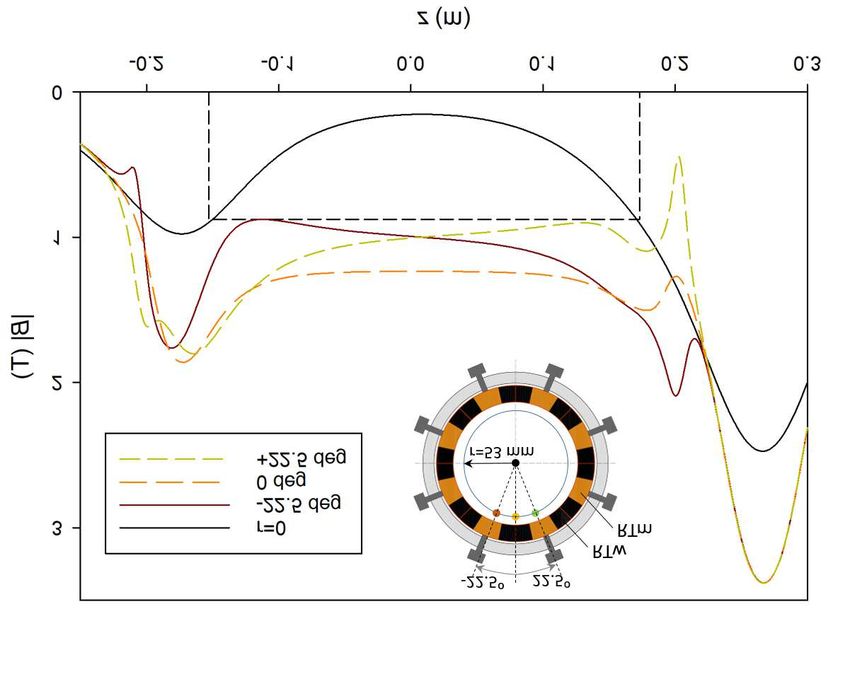
3

netic traps for most alkalis, running experiments in a room
temperature environment. However, experiments with hydro-
gen are different. Laser cooling is very difficult and ineffi-
cient due to the VUV wavelengths required for the excitation
from the electronic ground state. There is no other solution
to pre-cool the H gas to trappable energies than to use cryo-
genics and dilution refrigerators (DR). The flux of low-field
seeking H atoms (H↑) from a cryogenic H2 dissociator oper-
ating typically at ∼ 0.7 K is cooled by thermalization with the
physical walls. The dissociator is located at the fringing field
of a strong solenoid B ∼ 3.5 T where a negative field gradient
pushes H↑ towards the trapping cell. In order to avoid adsorp-
tion and subsequent recombination, the walls of the line be-        FIG. 2. Configurations of currents for Ioffe-Pritchard traps of differ-
tween the dissociator and the trapping cell need to be covered      ent types: a) race-track (RT) coils located in planes going through the
with a superfluid helium film. A dilution refrigerator is used      main IPT axis18 ; b) RT coils located symmetrically around the axis,
for cooling different parts of this line, finally cooling the gas   each Ioffe bar is a single RT linear current; c) the same as b) but with
                                                                    the double number of RTs. Each Ioffe bar is formed by two linear
to 100 − 200 mK. The gas in the trapping cell and the super-
                                                                    currents of neighbouring RTs10,11 ; d) the construction is not based on
fluid helium film should be isolated from the vacuum space of       RT coils. Ioffe bars are formed by the linear parts of the serpentine-
the DR. Construction and materials of the trapping cell should      like currents wound on a cylindrical surface (mandrel)12,13
provide high enough thermal conductivity while minimizing
heating due to eddy currents during magnetic field ramping.
   Hydrogen gas pre-cooled in the large IPT described in this       III.   CONSTRUCTION OF THE TRAP
paper will be used for several experiments including spec-
troscopy of GQS above the surface of superfluid helium15 .
                                                                    A.     Octupole magnet (OM)
Formation of a free surface of superfluid helium is only pos-
sible in the lowermost region of the whole setup below the
IPT (see Fig. 1). Cooling this region to ≤ 100 mK requires             Each Ioffe bar which provides magnetic field for radial con-
bringing a thermal link from the DR to this region. Satisfy-        finement should have a return path for closing the current
ing all the above mentioned requirements presents a serious         loop. In most IPTs the trap length along the axis is much
challenge. A reasonable solution was found by placing the           larger than its diameter. Therefore, the radial confinement is
IPT, trapping cell, and GQS experiment components inside            typically provided by elongated coils in the form of a race-
the vacuum can of the DR. The IPT magnets are cooled by the         track (RT). Currents in the neighbouring bars should be in op-
1K pot of the dilution refrigerator (Fig.1).                        posite direction. There are several possible ways to arrange
                                                                    the RT coils to obtain such a configuration.
                                                                       a) RT coils are arranged diametrically in planes containing
                                                                    the trap axis, so that the return path of each Ioffe bar is taken
Specifications summary
                                                                    far away from the trap axis and has a negligible influence on
                                                                    the trapping field (Fig. 2 a). Such configuration was used for
                                                                    trapping H in Amsterdam18. This design increases the radial
   In summary, our Ioffe-Pritchard trap is designed to meet the     size of the system and complicates the arrangement and wind-
following specifications:                                           ing of the pinch coils. It would be difficult to build a trap with
                                                                    a large inner bore diameter using this scheme.
    • Minimum trap depth 0.8 T (≈0.54 K);                              b) Race-tracks are arranged with the current bars at the
                                                                    equal distance from the trap axis, e.g. all the RT coils are
    • Effective volume for H gas at 50 mK ≥ 500 cm3 ;               located on the same cylindrical surface (Fig. 2 b). Since each
                                                                    RT coil has two linear current bars, N p /2 coils are sufficient
    • 3 T dissociator solenoid located above the upper pinch        to build a N p -poles magnet system for the radial confinement.
      coil;                                                         Thus four RT coils may be arranged symmetrically around the
                                                                    system axis to form the octupole trap. In this case, as can be
    • Operation at 1.5 K in the vacuum can of the dilution          seen in Fig. 2 b, the turn-around pieces of the race-tracks pro-
      refrigerator;                                                 duce non-zero fields on both ends of the system. These fields
                                                                    have opposite directions in the upper and lower ends of the oc-
    • Length of the system ≤ 0.6 m, fitting in the diameter         tupole magnet, implying that there is a zero field region in the
      ≤ 210 mm;                                                     trap center where the Majorana relaxation to untrapped states
                                                                    may lead to the rapid loss of the sample. The problem can be
    • Field ramping to 90% in ≤ 500 sec;                            solved by applying a bias field to the whole trap. The final
                                                                    field configuration becomes asymmetrical in the axial direc-
    • Operating currents ≤100-120 A;                                tion, and the effective volume of the trap is reduced.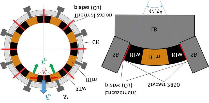
4
c) A similar construction as in b), but using twice as many
RT coils, allows obtaining a fully symmetrical field config-
uration. Now each of the Ioffe bars consists of two linear
RTs with parallel currents, and 8 RTs are required to build
the octupole configuration (Fig. 2 c). The end-pieces of the
RTs have alternating current directions, and do not produce
any field on the trap axis. Quadrupole traps built for trapping
atomic hydrogen9,10 and neutrons11 utilized such a scheme
with four RT coils. This configuration allows better mechani-
cal stability against the large magnetic forces between the lin-
ear pieces of the RT coils.
d) Ioffe bars can be produced by winding SC wires or cables
on a cylindrical surface in a serpentine way (Fig. 2 d). This
arrangement requires a special technique with robust fixing of
each winding on a special form. Using a small diameter wire
with a large number of turns makes the winding procedure
extremely complicated and expensive. Winding with bundles
of wires makes the process somewhat easier, but leads to an
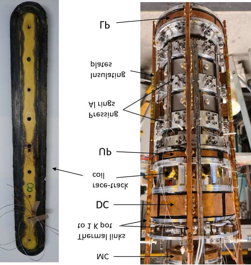
increase in the trap operating current. Such trap construc- FIG. 3. The configuration of currents and coils chosen for the Turku
tions were used to build octupole traps for the ALPHA12 and IPT trap (left); an IPT outlook with all coils and compressing Al
ATRAP13 collaborations for antihydrogen at CERN. The oc- rings (right). The octupole magnet inner bore is 112 mm, its outer
tupole segments in these traps cannot be disconnected from diameter is 150 mm. The overall height of the IPT including the dis-
each other and if something (e.g. catastrophic quench) hap- sociator solenoid is ≈ 600 mm. The race-track coils of the octupole
pens to one of them, the whole radial magnet system should magnet are put together with three 1 cm thick Al compressing rings
in the center of the system plus two rings extending from the pinch
be changed or re-wound.
coil forms. Tightening the M8 bolts "So", threaded through the com-
To meet the required specifications for our IPT, we selected pression rings into each race-track mandrel, moves the race-tracks
the type c) octupole configuration with eight RT coils which, out of the axis. The M5 screws "Si", four for each compression ring
together with the cores, form a thick-walled cylinder. The RT and two for each pinch ring, press the race-tracks inwards. They
segments are assembled and pressed together in a way similar were tightened with 2 N·m torque, preventing possible motion of the
to the staves of an old wooden barrel, as shown in Fig. 3. race-tracks due to magnetic forces directed outwards.
B. Axial solenoids is larger than the field in the center. The field near the edge
has a large radial component which interacts constructively
Two solenoidal coils are required to provide axial confine- or destructively with the octupole field (Fig.4) since the lat-
ment in the IPT trap. They are denoted as upper (UP) and ter changes direction for every second octupole segment. The
lower (LP) pinch coils. The pinch coils provide two field max- areas in the cylindrical surface of the bore of the octupole,
ima located close to the turn-around regions of the octupole where the radial field of the pinch is subtracted from the oc-
coils. For atomic hydrogen one more coil (DC) with a 3-4 T tupole field, are the possible trap leakage spots where the trap
field is needed to accommodate a cryogenic dissociator10,18 . barrier minimum Bwallmin is located. The IPT trap should be de-
Construction and manufacturing of these simple solenoidal signed to have sufficiently strong field in these regions.
coils is easy, and the pinches could generate much larger fields The dissociator solenoid geometry was chosen to obtain the
than the specified trap height. However, the fields of the field of ≥3 T near its inner wall. The fringing field of the
pinches and of the octupole have different symmetries. Their dissociator solenoid adds to the field of the upper pinch. This
vector sum varies considerably in the trapping volume. The allows a substantial reduction of the size of the upper pinch
optimization of the trap depth becomes a complicated task re- and its operating current.
quiring calculation of the total field in the volume of the trap.
We performed such calculations by numerical integration22
based on the Biot-Savart law. Dimensions of the pinch and C. Magnetic forces
dissociator coils and their location with respect to the octupole
center were varied to find the optimum configuration. The mu- Considerations of magnetic forces in the IPT construction
tual arrangement of the IPT coils with the current directions is are extremely important. The force experienced by the lin-
schematically shown in Fig. 3. ear part of the race-track in the field of 0.5 T perpendicular
The pinch coils cannot be very long due to the overall length to the bar current of 8.5 × 10⁴A (250 A×340 turns) is ≈ 15
limitation, while their diameter should be large enough to ac- kN. Such repulsive forces between the linear parts of individ-
commodate the whole octupole system. Typically for IPT ual race-tracks were reached during their tests and training at
traps, the diameter of the pinch coils is larger than their length. maximum currents. However, in the octupole configuration
This means that the field near the edge of such a short coil with 8 race-tracks shown in Fig. 3, each Ioffe bar is formed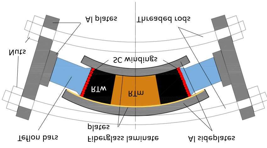
5

                                                                          FIG. 5. Pressing tool for linear parts of the race-track coils. RTw -
                                                                          race-track windings; RTm - race-track mandrel; SC windings - su-
                                                                          perconductive wire windings

FIG. 4. The configuration of currents and magnetic fields near the
edge of the lower pinch in the so-called "leakage spots" of the trap.     IV.   MANUFACTURING PROCEDURE
Due to the alternating direction of the field generated by the octupole
segments, for every second race-track, the radial component of this
field is subtracted from that of the pinch. These regions near the up-
                                                                             Each of the 8 race-track coils of the octupole, two axial
per(lower) edge of the lower (upper) pinch define the absolute mini-      pinch solenoids and dissociator solenoid were wound sepa-
mum of the trapping field Bwall                                           rately on its own mandrel. For the race-track mandrels we
                             min on the wall of the trapping cell.
                                                                          used bronze and aluminium alloy for the axial coils. Thermal
                                                                          expansion of these materials is not much different from the
                                                                          composite winding of the coils and both were readily available
by two linear conductors of the race-tracks carrying parallel             from local suppliers. Race-track mandrels were milled from
currents. Attractive forces between these current bars (red ar-           142 mm o.d. bronze tube with a wall thickness of 12 mm.
rows in Fig. 6) have no radial component and create a large               Side surfaces adjacent to the linear parts of the race tracks
compressive stress which binds them strongly together. The                were milled with such an angle that their planes intersect ap-
net force experienced by such Ioffe bar from the other 7 bars             proximately on the tube axis (see Fig. 6).
in the central region of the trap is directed outwards (blue ar-
row in Fig. 6). For the desired operating conditions with the
trap depth of 1 T we obtain ≈ 460 N per 10 cm of the bar                  A.    Coil winding
length. This corresponds to the pressure of ≈ 0.14 bar and is
much smaller than the tangential compressing forces between                  All coils were wound with 0.55 mm thick (bare dia. 0.50
the linear RT parts. This means that for our construction of the          mm) Luvata OK-54 superconductive wire23 which contains
octupole, the magnetic forces make the whole assembly me-                 54 NbTi filaments of 45 um diameter in copper matrix with
chanically stronger and the octupole can operate without any              the nominal Cu to SC ratio 1.33 and outer diameter of
extra stressing force from outside, except for a weak bind-               0.5/0.55 mm bare/insulated. The short sample critical current
ing to keep the segments together at zero current. This pre-              is 206/340 A in a field of 5.4/3.0 T at a temperature of 4.2 K.
stressing force is provided with the Si bolts screwed into the               For winding the race-tracks, 5 mm thick aluminium side
compressing rings (Fig. 6). Enhancement of the mechanical                 plates were bolted to the bronze mandrels from the inner and
strength of the octupole due to its own magnetic forces was               outer curved sides (Fig. 5). The inner/outer surfaces of the
confirmed in the tests of the IPT.                                        plates have the same curvature as the outer/inner surfaces of
   Interaction between the turn-around sections of the race-              the mandrels and the desired curvature of the octupole system.
tracks and the pinches creates another problem. Cur-                      Fibreglass laminate plates of 0.3 mm thickness were placed
rents in these end-pieces change direction from parallel to               between the aluminium side plates and the mandrels.
anti-parallel with respect to the pinch solenoid. We per-                    All coils were wet wound using Stycast 2850FT epoxy with
formed a numerical calculation of this force using Biot-Savart            Catalyst 11. The bobbin with the SC wire was loaded with a
software22 . For our IPT, the net force to each curved region is          weight keeping ∼ 80 N tension along the wire during winding.
fairly large ≈ 2 kN. The stability of these turn-around regions           However, this tension is not transferred to the linear parts of
is also improved by the strong attractive forces between the              the race tracks. The wires there remain nearly free and require
linear RT parts. In addition, we used the bolts Si screwed to             additional compression. In order to provide sufficient strength
the pinch cores and three compressing Al rings (Figs. 3, 6).              to the linear parts and achieve homogeneous filling by epoxy,
The bolts press onto the bronze mandrels upon tightening and              we pressed the linear parts from both sides using teflon and
provide an extra force on the RTs directed towards the trap               aluminium bars screwed together with 8 M6 bolts providing
axis.                                                                     a total force of ∼ 1 kN onto the winding layers (Fig. 5). For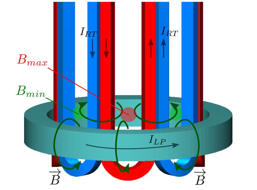
6

the reinforcement and extra insulation of the coil windings we
used Zylon HM273 filament24 . The winding procedure of the
RT layer was as follows: a turn-to-turn winding of a full layer
(19 turns), painting by epoxy with a brush, winding a Zylon
filament layer (between the SC wires) on top of the epoxy,
and application of extra epoxy to cover evenly all surface of
the layer. After winding 2-4 layers, the pressing bars were in-
stalled and screwed together as shown in Fig. 5. Excess epoxy
was removed from the turn-around regions, and the race-track
was moved to the oven for curing at 85 ◦ C. Usually, 2-4 layers
were produced per day, followed by an overnight curing. Each
race-track consists of 18 layers. In total we manufactured 10
                                                                           FIG. 6. Cross section of the octupole magnet assembly with the race-
nearly identical race-tracks, eight of which were assembled                track coils and Al ring (left). Cross section of the final race-track
together in the octupole magnet, and two kept in stock for a               shaping tool (right). Si - pressing bolts, CR - Al compression ring;
possible replacement/repair.                                               SB - Al side-bar. LB - Al lower bar. Magnetic forces acting of the
   The pinch and dissociator solenoids were wound using the                RT bars are shown on the left picture with the arrows: red arrows Fc
same tension, epoxy and Zylon reinforcement. Since no extra                - for the attractive force between the flat RT regions; green arrows Fp
compression was required, 4-5 layers could be done during a                - mandrel pressing forces from the Si screws; blue arrow Fo directed
day followed by overnight curing. The winding numbers of                   outside - the net force acting from the other 7 current bars.
all coils are presented in Table I.

                                                                           a pre-stressing force on them directed towards the IPT axis.
TABLE I. IPT coil parameters: Nw - number of windings; L - induc-          Final adjustment of the tubular shape was done by loosening
tance, H; Ic @4.2 - critical current reached in individual coil tests at   the So and tightening the Si bolts using for the latter a final
4.2 K, A; Ic @1.4 - critical current reached in individual coil tests at   torque of ≈ 2 N·m .
1.4 K, A; It - calculated current for reaching the target trap depth of
0.8 T for the simultaneous operation of all coils, A
                                                                              The RT thermalization plates and the RT mandrels were
                                                                           thermally linked to four 12 mm diameter copper rods go-
 Coil        Nw          L           Ic @4.2 Ic @1.4        It
                                                                           ing up and are attached to the 1 K pot of the cryostat (1 K
 RT          340         0.04        240±10
 OM          2720        0.43        173        166         120            bars). All axial solenoids were thermalized using altogether
 LP          1400        0.53        120        131         92             8 curved copper plate segments glued to the coil outer sur-
 UP          760         0.2         170        > 100       32             face (Fig. 7) and linked to the 1 K bars (Fig. 7). The total
 DC          3450        2.4         130        130         100            length of the 1 K bars from the IPT bottom to the 1 K pot
                                                                           is ≈1.4 m. Special attention was paid to avoid closed cur-
                                                                           rent loops through the thermal links. Eddy currents induced
                                                                           in such loops could cause excessive heating during the field
                                                                           ramps. All connections between the copper plates and verti-
B.   IPT assembly                                                          cal bars were done via thin insulating laminate plates or 30 µ m
                                                                           thick Kapton films.
   The winding procedure described above does not ensure ac-
curate enough final dimensions for the race-track coils. In
order to get a good, tight and symmetrical assembly of the                 C.   Current leads
octupole segments, we made a final processing of their linear
parts for each RT matching the angular segment of ≈ 44.5◦ .                   Wire connections of the race-track coils were done by sol-
This angle is slightly smaller than 45◦ in order to leave space            dering the wires to a copper plate over the length of ≈ 30
for extra thermalization plates between the RTs. The RTs af-               cm. We were aware that even for such a long soldering, joint
ter winding, together with 0.3 mm thick encasement copper                  resistances may cause a substantial overheating of the mag-
plates, were put into a special form (Fig. 6). Stycast 2850                net system under operating conditions in vacuum. In order
epoxy was applied to fill the gap between the linear RT parts              to avoid heating of the joints, we made electrical connections
and the encasement plates, and cured. Putting together the                 utilizing the cold welding techniques of the SC strands of the
RTs, we installed extra 0.5 mm thick thermalization plates                 wires25 . The SC filaments were freed from the copper ma-
pressed between the encasement plates. The octupole assem-                 trix by etching in nitric acid. The strands from two ends were
bly forms a tubular construction with an outer diameter of 137             twisted together and pulled into a small piece of copper tube
mm and and a clear bore of 111 mm. Pinch coils and disso-                  with tight packing. Finally, the end was pressed with a 20 kN
ciator solenoid cores are fixed on the OM using the So bolts               force. Current leads of all the IPT components from the coils
(Fig. 3) screwed to the RT mandrels via the holes in the Al                up to the top of the vacuum can of the DR were built from the
cores of the pinches and three compressing rings located be-               same SC wire as was used for the coils, using the same cold
tween the pinches. The Si bolts (16 per each RT) screwed in                welding joint technique.
the Al compressing rings press onto the RT cores and provide                  The SC wires were fed through the vacuum feedthroughs
7
were done without any extra support, training the coils just on
their mandrels as they came out after manufacturing. At the
maximum currents, the repulsive force between the linear RT
parts reaches 4.3 kN per 10 cm of length. To our surprise,
all coils withstood such force and no damage was observed.
This proves a very good mechanical strength of the wire bars
re-enforced with Zylon, and a proper choice of the winding
procedure. Being immersed in liquid helium, the race-track
coils allowed fairly high field ramping rates. Energizing to
150 A current could be done in 50 sec.
Measurement of the magnetic field was performed with
an axial cryogenic Hall probe HGCA-3020 (Lake Shore
Cryotronics27) fixed at the distance of ≈ 5 mm from the cen-
ter of the linear part of the race-tracks. The measurements
provided ≈ 10% scatter for different RTs, matching the cal-
culated value with the same accuracy. Such an error can be
explained by inaccuracy in the probe positioning.
A. Tests of the IPT in liquid helium at 4.2 K
After testing the race tracks, the whole IPT was assembled
and pre-stressed as described above. The first two perfor-
FIG. 7. Photographs of an individual race-track coil just after wind- mance tests of the whole system were done in the main he-
ing and before finalizing its shape (left) and of the final IPT assembly lium bath of the DR cryostat at 4.2 K. The octupole assembly
hanging in the dilution cryostat (right). was tested and trained first. The maximum current of 173 A
was reached after four quenches with the first one occurring at
130 A. Then, the axial coils were tested separately. The lower
on the top flange of the vacuum can and soldered to the leads pinch reached 130 A, the upper pinch 170 A, and the disso-
going through the helium bath of the cryostat up to room tem- ciator solenoid 130 A after 2-3 quenches. These maximum
perature. The lower end of the leads in the cryostat neck and values were reproducible within 10-15% for the different test
helium bath were built from commercial High-Temperature runs.
Superconductor tapes26 . We built four pairs of leads, one for Charging all coils together, we aim at reaching the maxi-
each of the IPT components: the octupole (nominal current of mum trap depth ∆Bt = Bwall min − Bmin defined as the difference
150 A), the lower pinch (130 A), the upper pinch (100 A), and between the field minimum Bwall min at the inner wall of the cylin-
the dissociator coil (100 A). drical trapping cell (r = 53 mm) and the absolute field mini-
We used passive quench protection which was done with mum Bmin in the trap center. Bwallmin is located in the IPT leak-
protection resistors connected in parallel to each of the IPT ing spots as described above. By a numerical calculation, we
coils made from 0.8 mm dia. pieces of stainless steel wire. found the following current combination which allowed us to
Their resistance was ∼ 1% of the coil resistance at room tem- reach the desired trap depth ∆Bt = 0.8 T: 120/ 92/ 32/ 100
perature. Then, during a quench ∼ 90% of the stored coil A for the currents in the OM/ LP/ UP/ DC coils respectively,
energy should be released in the protection resistor. The resis- which we set as the target of the IPT performance. Desired
tors were placed in the vapour of the helium bath of the DR trap depth in the upper end of the IPT can be reached with dif-
cryostat, just above the maximum helium level. They were ferent combinations of the UP and DC currents since the fields
soldered to the lower ends of the HTS leads. This allows a of these coils add together below the UP. However, ≥100 A
substantial reduction in amount of liquid helium evaporated current in the DC coil is required to ensure ≥3 T field for the H
in a quench. dissociator as specified for our IPT. This leads to a fairly low
current in the UP. Below, we will present results of the tests
for the various coil combinations and report currents relative
V. COIL TRAINING AND PERFORMANCE TESTS to the specified above target values It .
Testing the coils together, we found that if we charge the
Each RT was tested and trained in liquid helium at 4.2 K in lower pinch first to 80-90 A and then try to energize the oc-
a small cryostat. Typically, we had the first quench at 130-150 tupole, a quench occurs at currents well below 100 A. Chang-
A, reaching 230-250 A after 5-8 quenches. For a single race- ing the charging order so that first the octupole is loaded first
track coil, the maximum field is reached near the inner sur- to ∼100 A, allowed reaching currents above 100 A in the
face of the turn-around ending. With 250 A current the maxi- lower pinch. Increasing further the OM current, the steady
mum field of ≈ 4 T was reached. This is ≈ 85% of the short operation of both coils was reached with 130/ 100 A currents
sample critical current. The tests of the individual race-tracks in the OM/ LP combination (108% It ). The observed depen-8
dence of the performance on the charging order confirms that cal current of the SC wires increase by ∼ 30% at 1.5 K, and
the magnetic forces acting between the race-tracks improve no changes were done for the mechanical connections of the
the stability of the whole system. IPT components, we expected that no quench should occur
Tests of the upper axial coils together with the octupole before we reach the same critical currents as in the wet tests.
showed a slightly better performance. We reached currents However, since the system behaviour at quench is an impor-
of 138/ 40/ 115 A for the OM/ UP/ DC combination (115% tant experience, individual IPT components and their simple
It ). combinations were quenched for a few times.
Finally, all coils were energized together, raising first the First we ramped the LP and then the OM to quenches. The
octupole current to 100 A, then charging all others to ∼ 70% former was quenched twice, and the latter four times. We
of It and further increase of all currents in proportion to the have not observed training behavior, and the maximum cur-
target values. Finally, we reached 130/ 100/ 40/ 105 A for rents were within 5%, the same as in liquid helium at 4.2 K.
the OM/ LP/ UP/ DC simultaneous operation (108% It ). The Each quench boiled off all (≈ 3 l) helium in the 1 K pot and
currents reached in the 4.2 K tests are listed in Table I. warmed the magnet system up to 30-40 K. In order to facilitate
The magnetic field was measured in the center of one of the fast recovery, a small amount of exchange gas was admitted in
race-track bronze cores at the distance of ∼ 52 mm from the the vacuum space establishing a good thermal contact to the
axis using the mentioned above Hall probe. The results agreed main helium bath. The 1K pot and the IPT cooled back and
with the calculations to within about 10% accuracy. were ready for the next ramp after ≈ 30 minutes.
Several tens of quenches were observed altogether during The tap voltages across each RT of the OM and the LP were
the "wet" tests in helium. Voltage taps were connected to each monitored during quenches. No "bad" RT with reproducible
segment of the octupole and to each axial coil. Recording first quench behaviour was detected, indicating that they are
the voltages over the taps during quenches allowed identifying all of about the same quality, and so far none of them need a
which coil quenches first and triggers transition of the whole replacement. Next, we tested the UP and DC, energizing them
system. In the liquid helium tests, sometimes one or two of to 100 A and 130 A respectively. Stable operation without
the coils remained superconducting and energized while the quenches was observed. Since these currents well exceeded
others quenched. The OM and the LP recovered a few seconds the target values, we did not make an attempt to go further.
after the quench with a total evaporation of 5-7 liters of helium Then, the OM and the LP combination was tested. We
at the maximum current. The DC quench was performed only charged the OM to 80% of the target current, then ramped the
twice. This coil has the largest stored energy and its quenches LP to the same rating, then slowly increased both currents.
evaporated more helium, about 10 liters. We reached 106% of It with continuous operation during 30
min and no quench was observed.
Then, the OM, UP and DC were tested together, ramping
B. Tests of the IPT in vacuum at 1.5 K first the OM to ∼100 A. We reached the currents 138, 40 and
115 A (115% It ) respectively for these coils when the quench
After the tests in liquid helium, the IPT including the 1 K occurred. This quench had the strongest effect with largest
bars and current leads was mounted in the vacuum space of overheating and recovery time since the largest part of the
the dilution cryostat (see Fig. 7). The whole assembly was magnetic energy is stored in the DC coil. No damage occurred
centered in the 210 mm i.d. vacuum can of the dilution refrig- after this event. The system recovered to the initial state and
erator. Several thermometers were fixed to every IPT coil and we were able to continue the tests.
to the magnet leads in the helium bath. With zero currents all Finally, all the IPT coils were energized to 100% of the tar-
IPT coils reached ≈ 1.5 K, very close to the temperature of get current and kept for 15 minutes without a quench. We did
the 1 K pot. not keep all currents in the IPT longer than that because con-
As expected, the main difference of the tests in vacuum was tinuous operation warmed the current leads approaching crit-
a substantial heating of the coils during the current ramps. ical values for the HTS tapes. On the other hand, longer op-
This was caused by the eddy currents in the coil mandrels eration times are not required in experiments with atomic hy-
and in possible parasitic loops between the thermal links and drogen. We expect that the trap will be loaded with hydrogen
1K bars. In vacuum we had to reduce the ramping speed by atoms for 5-15 minutes. Possible improvement for reaching
nearly an order of magnitude compared with the tests in liq- longer continuous operating times are suggested below. We
uid helium. Charging any of the coils alone to 90% of the have not observed any noticeable heating of the IPT assembly
target required ∼10-15 min and caused a heating of the IPT to at the steady current state when the field ramps were stopped.
≈ 3.5 K. Analysing the temperature gradients during the field This means that the soldering and cold welding connections
ramps, we came to the conclusion that the bottleneck in the are good enough and do not impose heating problems.
heat transfer is caused by poor thermal contact between the 1
K bars and the 1 K pot. Several simple solutions to improve
this contact will be discussed below. VI. MAGNETIC FIELD PROFILES
We expected that quenches in vacuum may cause more se-
rious troubles than in liquid helium and a much higher risk Calculations of the magnetic field were performed at the
of IPT damage. Therefore, for the tests in vacuum, we did stage of designing the IPT for various configurations of its
not make extensive training of the whole IPT. Since the criti- components and their mutual arrangement in order to reach9
FIG. 8. Magnetic field profiles along several vertical lines parallel to
the IPT axis (z-axis) at the distance of 53 mm from the trap axis. The
locations of these lines in the horizontal cross-section are shown in
the insert. Vertical dashed lines mark locations of the top and bottom FIG. 9. 2D colour plot of magnetic field in the cross-section at z =-
of the trapping cell. Plots are calculated for 100% of It (0.8 T trap 113 mm where the trap minimum (leakage spot) is located. Colour
depth). legend provides field in the range 0.5-1.1 T. The black circle cor-
responds to the trapping cell inner surface at = 53 mm. Plots are
calculated for the 100% of It (0.8 T trap depth).
the specified parameters. We have not performed a detailed
measurement of the field profile in the IPT using e.g. a Hall
probe. This would require a complicated probe positioning the trap are sufficient to confine > 1015 hydrogen atoms at 50
system. The calculations based on the Biot-Savart law provide mK. This can be reached at low densities ∼ 1012 cm−3 when
reliable results, and a simple check for a few points in the IPT the decay of the sample caused by dipolar relaxation occurs
was considered to be sufficient. These checks were performed on the time scale of ∼10 min. Our trap performed equally
as described above during the coil tests in liquid helium and well in a bath of liquid helium at 4.2 K and inside the vac-
their results agreed well with the calculations. In Fig.8 the uum can of the dilution cryostat at 1.5 K. This indicates that
axial magnetic field profiles are shown for the 80% of target the performance is not limited by the critical currents of the
currents, reached in the tests at 1.5 K. superconductors, which increase by ≈ 30% at lower operat-
Special attention was paid to find the trap leakage spots ing temperature. The mechanical stability of the IPT assem-
which define the minimum trap depth. As described below bly against magnetic forces is a major concern for large size
they are located above the LP and below the UP in the regions traps, and it is clear that it is the main limitation also here. We
where the radial component of the pinch coils adds destruc- found that the construction of the octupole magnet built with
tively to the field of the octupole. For the lower/upper pinches, eight race-track coils pressed from outside by metal rings, as
these spots appear at the distance z ≈ −113/ + 131 mm from the staves of a wooden barrel, helps to improve the mechan-
the center of the IPT. A 2D colour plot for the crossection go- ical stability. This design also allows an easy disassembling
ing through the lower pinch leaking location is presented in of the IPT and replacing of any of its components including
Fig. 9. From the plots in Figs. 8 and 9 one can see that the individual race-track coils.
magnetic field Bwall The maximum trap depth is determined by the difference of
min ≈ 0.95 T in the leaking points on the inner
surface of the trapping cell (r = 53 mm) was reached during the magnetic field minimum on the inner surface of the trap-
a steady operation of the IPT at 4.2 and 1.5 K. Taking into ping cylinder and the field Bmin at the trap bottom. The field
account the Bmin ≈ 0.15 T field in the trap center, this justifies Bmin ≈ 0.15 T reached in the tests of our IPT is fairly large
that the trap depth of ∆Bt ≈ 0.8 T was reached. The field at the and is not required for the experiments with trapped H. It is
inner bore of the IPT (r = 56 mm) is ≈1.1 T corresponding to a consequence of the short distance between the pinch coils
the trap depth of ≈ 0.95 T. constrained by the overall IPT length. A simple solution to re-
duce Bmin is to place an extra trim coil in the center of the IPT
between the pinches producing a field of opposite direction to
that of the pinches. Cancellation of the 0.15 T field to nearly
VII. CONCLUSIONS AND POSSIBLE IMPROVEMENTS zero can be done with a relatively weak solenoid which will
not change significantly the field in the leakage spots. This
We attained the trap parameters specified above for exper- simple modification would deepen the trap by ≈ 15%.
iments with atomic hydrogen. The volume and field depth of The maximum ramping rates of the IPT currents are lim-10
ited now by a poor thermal contact between the trap and the refrigerator cryostats operating with pulse tube cryocoolers.
1 K pot of the refrigerator. There are several ways to improve
this thermal link. We found that the main bottleneck in the
heat transfer is the small contact area between the copper rods VIII. ACKNOWLEDGEMENTS
serving as thermal links and the liquid helium inside the pot.
The main function of the 1 K pot of a dilution refrigerator is to This work was supported by the Academy of Finland (Grant
condense return 3 He using a dedicated heat exchanger inside No. 317141), the Jenny and Antti Wihuri Foundation, Inter-
the pot. Normally, the bottom of 1 K pot is not designed to national Emerging Action (IEA00552) "Quantum Reflection
transfer large amounts of heat. This can be improved by in- of Cold Hydrogen", CNRS. The authors would like to thank
stalling copper rods from the IPT into the pot and increasing M. W. Reynolds (Ripplon Software Inc.) for providing Biot-
the contact area with liquid 4 He using sintered heat exchang- Savart Magnetic Field Calculator, Raphaël Janiv (Teijin Fron-
ers. Another possibility is to transfer heat from the IPT using tier Europe GMBH) for help with Zylon filament. We also
tubes filled with superfluid helium instead of the copper rods. thank Simo Jaakkola for commenting the manuscript.
1
A continuous operation of the IPT at full current will be- H. Friedberg and W. Paul, Naturwissenschaften 38, 159 (1951).
2 C. V. Heer, Rev. Sci. Instr. 34, 532 (1963).
come possible after simple improvements of the current leads. 3 V. Vladimirski, Zh. Eksp. Theor. Fiz. 39, 1062 (1960), [Sov. Phys. JETP
Our cryostat has no liquid nitrogen bath, the current leads go 12, 740(1961)].
through its neck and are cooled by helium vapour. The natu- 4 D. E. Pritchard, Phys. Rev. Lett. 51, 1336 (1983).
ral boil-off of our cryostat of ≈ 0.5 l/h is rather low. With the 5 M. S. Ioffe, unpublished. The idea was presented at the first Conference
full currents in the IPT leads the boil-off increases by ∼ 50%, on Fusion Research held by the International Atomic Energy Agency in
which is still not sufficient for cooling the leads. An obvious Salsburg, Austria, September 1961.
6 H. F. Hess, Phys. Rev. B 34, 3476 (1986).
solution is to increase the cross-section of the leads between 7 M. H. Anderson, J. R. Ensher, M. R. Matthews, C. E. Wieman, and E. A.
the room temperature and the HTS tapes. This will increase Cornell, Science 269, 198 (1995).
8 K. B. Davis, M.-O. Mewes, M. R. Andrews, N. J. van Druten, D. S. Durfee,
the flux of helium vapour in the neck and improve cooling of
the leads at the expense of the higher helium boil rate. This D. M. Kurn, and W. Ketterle, Phys. Rev. Lett. 75, 3969 (1995).
9 D. G. Fried et al., Phys. Rev. Lett. 81, 3811 (1998).
would not be a problem in modern dry dilution refrigerators 10 J. M. Doyle, Ph.D. thesis, MIT (1991).
utilizing two or three cryocooleres with cooling powers up 11
L. Yang et al., Rev. Sci. Instr. 79, 031301 (2008).
to 1.5 W at 3 K. In fact the cooling power of a single cry- 12 W. Bertsche et al., Nucl. Instr. and Meth. in Phys. Res., A 566, 746 (2006).
13 E. Tardiff et al., Nucl. Instr. and Meth. in Phys. Res., A 977, 164279 (2020).
ocooler is twice as large as the current lead heating in our
14 https://grasian.eu/.
tests described above. One should also point out that the cool- 15 S. Vasiliev et al., Hyperfine Interact. 240, 14 (2019).
ing power of the cryocoolers is very large at their 40 K stage, 16 A. Lagendijk, I. F. Silvera, and B. J. Verhaar, Phys. Rev. B 33, 626 (1986),
to which the ends of the HTS tapes could be thermally pinned. URL https://link.aps.org/doi/10.1103/PhysRevB.33.626.
17 J. T. M. Walraven, Atomic Hydrogen in Magnetic Traps (IOP, Bristol, 1996),
The possibility of operating in vacuum is especially valu-
able for the integration of the IPT into the standard dry dilu- Quantum Dynamics of Simple Systems.
18 R. van Roijen, Ph.D. thesis, University of Amsterdam (1989).
tion cryostat where there is no 4 He bath. The large diameter of 19 V. Bagnato, D. E. Pritchard, and D. Kleppner, Phys. Rev. A 35, 4354 (1987).
the vacuum space of a typical dry cryostat and the location of 20 K. Tsuchiya, K. Egawa, K. Endo, Y. Morita, and N. Ohuchi, IEEE Trans-
the plates where the 40 K and 4 K temperatures are reached, is actions on Magnetics 27, 1940 (1991).
21 P. Huffman et al., Cryogenics 64, 40 (2014).
much more convenient for installing the IPT allowing simpler 22 BiotSavart Magnetic Field Calculator, M. W. Reynolds, Ripplon Software
and shorter thermal links.
Inc., Burnaby, BC, Canada. http://www.ripplon.com.
In conclusion, we developed a large Ioffe-Pritchard trap for 23
Luvata Pori Oy, Kuparitie 5, FI-28330 Pori, Finland. www.luvata.com.
24 Manufactured by Toyobo Co., Ltd. HM273 filament was used
desktop experiments with atomic hydrogen. The trap has the
largest volume and about the same strength as earlier traps with the yarn count 273dtex, containing 166 12µ m dia. filaments.
https://www.toyobo-global.com/seihin/kc/pbo/zylon_pro.html.
used for cold atoms or anti-atoms. The trap construction al- 25 S. Phillip, J. V. Porto, and J. M. Parpia, J. Low Temp. Phys. 101, 581 (1995).
lows an easy replacement of any of its components, including 26 2G HTS wire 04-30Ag-5Cu-60H from S-Innovations, 20-2 Nauchnyi
the race-track coils of the octupole magnet. Our IPT operates proezd, 117246 Moscow, Russia, https://eng.s-innovations.ru/.
27 LakeShore Cryotronics, Inc., https://www.lakeshore.com/.
in vacuum and can be easily integrated in modern dry dilutionYou can also read