A PV generation system based on P&O MPPT algorithm and SVPWM inverter for standalone applications
←
→
Page content transcription
If your browser does not render page correctly, please read the page content below

A PV generation system based on P&O MPPT algorithm
 and SVPWM inverter for standalone applications
 Duha Khalf1, Kadhim H. Hassan2, Diyah K. Shary3
 {duhakareem249o0ll@gmail.com1,k.hassan@stu.edu.iq2, diyahpower@stu.edu.iq3 }
 1,2,3 Basra Engineering Technical College, Southern Technical University, Iraq

 Abstract. The output of photovoltaic cells continues to change with surrounding
 environments, therefore, the maximum power point of the solar cell relies on the
 amount of solar irradiation and environment temperature. Maximum Power Point
 Tracking (MPPT) technology is utilized in photovoltaic systems to take entire
 advantage of output power for Photovoltaic cells. Power Inverters also is an
 important side of Photovoltaic power generation. This paper proposed a Perturb and
 Observe (P & O) MPPT algorithm with space vector pulse width modulation
 (SVPWM) control method for a three-phase complete stand-alone Photovoltaic
 generation system. The proposed PV generation system is implemented into Matlab
 / Simulink. Simulation results show the proposed stand-alone Photovoltaic system
 can achieve the excellent execution of MPPT and get the output voltage in high
 quality. The system is tested and verified using a solar cell Kyocera Solar
 KD215GX-LPU PV module.

 Keywords: Photovoltaic system (PV); Maximum PowerPoint Tracking (MPPT);
 Space vector pulse width modulation (SVPWM)

 1. Introduction
 Because of the increasing demand for energy, pure, environmentally and sustainable energy is
 required. Solar energy, a type of renewable energy indicating a lot of interest in meeting growing
 load demands. Most of the solar energy sources that can be used to produce clean electricity are
 available for free everywhere, despite the cost of composition is high, the cost of operation is very
 low [1].
 Solar cells are variable current or voltage sources because they depend on the variation in
 temperature, irradiation, and load. Due to the solar cells have a low efficiency, Maximum power
 point tracking (MPPT) technology is utilized to supply the output of the solar cell effectively. The
 technology can source maximum power from different sources by utilizing a controlled DC-DC
 boost, converter with a tracking algorithm inserted between the solar cell and the load [2]. In this
 paper, Perturb and Observe (P & O) Technique is used due to its low cost, easy implementation, and
 good execution [3].
 In photovoltaic power generation systems, inverters that convert DC power from solar cells into
 AC power for grids are becoming more popular every day. Inverters are an important unit in the
 power regulation part of PV systems that use a variety of DC to AC converters. Inverter tasks in a
 power generation system including DC to AC conversion, system control, and output power quality
 assurance with various protection mechanisms [4]. Multi-level inverters with Pulse Width

IMDC-IST 2021, September 07-09, Sakarya, Turkey
Copyright © 2022 EAI
DOI 10.4108/eai.7-9-2021.2314775
Modulation (PWM) control are becoming more important. They have many additional advantages
over other topologies and are extra efficient [5].
 In [6] proposed a switched ZSI to achieve higher voltage gain than a conventional inverter. A
better pulse width modulation (PWM) was applied [7-8]. In this work, a structure of a photovoltaic
generator system is proposed based on the perturb and observe optimised algorithm and space vector
pulse width modulation technique for 3-phase pulse width modulation inverter. The simulation result
shows an increase in output power with better performance in output voltage and current.

2. Photovoltaic modeling
Solar cells convert the sun's rays into DC power. This is a process known as the photoelectric. A
Photovoltaic consists of multiple PV cells might found in parallel and series to increase the voltage
and current in the array. There are many types of solar cell modules. A solar cell using a single diode
model, is shown in Figure 1 [6] [3].

 Figure 1. The single-diode model [7]
IPV = IPH − ID − Ip (1)

 G
IPH = IP + K I (T − Tref ) (2)
 1000

 qEg 1 1
 T 2 [ ( − )]
 nk Tref T
IO = Ido ( )e (3)
 Tref

 VPV
 NS
 +IPV RS
IP = (4)
 RP
The output current of the Photovoltaic model is given as [8]

 ( + )
 −1
 = − [ ] − IP (5)

Where : photovoltaic voltage, : diode reverse saturation current, : photovoltaic cell
output current, : photogeneration current, : short-circuit current, : diode current, k: The
constant of Boltzmann that equal to ((1.38) * 10 -23 J / K), q: the charge of electrons (1.602 * 10 ^
-19 ℃), : Series resistance of solar cells, : Parallel resistance of solar cells, n is diode emission
coefficient, T is Kelvin unit Ambient temperature, the reference absolute temperature, : the
silicon bandgap energy (1~3) eV, ∶ the current temperature coefficient in a short circuit and :
Reverse current of the diode [9].
In the ideal case, Rs is equal to zero and Rp is infinite. Industrialists try to reduce the effects of
both resistances to improve the product [9]. In this paper, a solar cell module of the type Kyocera
Solar KD215GX-LPU PV is considered, in which the table parameter is listed below:

 Table 1. Parameters of the Kyocera Solar KD215GX-LPU PV panel used in this task.

 Quantity Value
 26.6 V

 8.09A

 215.194W

 33.2V
 8.78A
 (0.02 ± 0.015) %/°C
 −(93 ± 10) mV/°C
 54

3. The Perturb and P&O Algorithm
 The MPPT technology is utilized from solar panels to get maximum power efficiency. PV
modules are not constantly concerning the power supply and the V-I characteristics are non-linear
making them difficult to use. This is observed using a DC-DC boost converter by changing the duty
cycle of the entire MPPT algorithm. A flow chart for the P & O MPPT is seen in Figure 2 [3]. Over
the last few years, many techniques have relied on MPPT. Many MPPT algorithms are reported
[10]. In our PV generation system, we used the Perturb and Observe (P & O) algorithm. The P & O
algorithm is the most well-known used algorithm due to its low cost, good execution, and simple
implementation. As shown in Figure 3, the algorithm has a small disturbance, at the start, the solar
cell voltage, current, and power P1 are acquired, after which the operating voltage of the
photovoltaic model is perturbed by a slight increase. It then generates a new power P2. Therefore,
the change in power ΔP is measured by the variation between P1 and P2. If the fluctuation is equal
to the positive sign, the operating point will approach MPP due to the disturbance of the operating
voltage. In this case, the maximum PowerPoint can be obtained and the applicable voltage
 can be measured. Therefore, extra perturbations can be inserted in the same direction to
achieve MPP. On the other side, if the variation is equal to negative, the algorithm decides to inverse
the whole operation. The change in power must be in the same direction for more perturbations [2],
[11], [12].

Figure 3. The P&O MPPT algorithm

 Figure 2. The hill-climbing for the ‘P&O’ algorithm

4. Principle of three-phase Space Vector Pulse Width Modulation (SVPWM)
 The 3-phase Voltage Source Inverter (VSI) principle is controlled by utilizing the switching
signal generated by SVPWM technology. For the top switch on the same leg is turned,on whenever
the bottom switch, is turned off, so it is used to set the inverter. Figure 4 indicates the voltage
waveform of the inverter leg. One leg of the inverter will change its state and will remain fixed at
60° for the next cycle (360 °). There are 6 discrete values of leg voltage so that one cycle is (360 °).
The eight switching cases on the inverter leg needed to code the upper arm case are binary switched
to 3 bits. Table (2) lists the switching cases. Here, the switch is on for a bit (1) while the switch for
a bit (0) is off [13][14].

Table 2 shows the spatial vectors that exemplify the eight switching cases of VSI. The six non-
zero vectors (V1 to V6) are divided into six sections of the hexagon in the complex plane with the
center of the hexagon between the two zero vectors. (Null vector) as seen,in Figure 5 [11]. The
angle, for non-zero vectors is 60. The reference voltage vector ( ) is generated by switching
between two closer active space vectors and one zero vector. This exemplifies the three-phase AC
voltage of the space vector power width modularity method. The VSI is varied by changing the
magnitude and frequency of . SVPWM based on,the voltage of the fixed reference,frame
by converting the 3-phase voltage of the ABC reference of the fixed reference,frame utilizing Clark's
transformation. The maximum capacity of the output voltage can be obtained by SVPWM
technology. It is shown thatt he radius,of the largest,circle formed into the,hexagon. [15]. Three
steps should be applied to perform the SVPWM [13].
1- determine , , and angle, .
2- calculate,the time,durations 1 , 2 , and 0 .
3- calculate the switching states based on the above step

 Figure 4. The voltages waveform of the 3-ph VSI

 Table 2. The switching table and output voltages of the VSI

 Step-1 calculates the switching , and by using Clark’s transformation[15].

−1 −1
 1
 2 2 vA
 Vα 2 √3 −√3
[ ] = 0 [ vB ] (6)
 Vβ 3 2 2
 vC
 1 1 1
 [2 2 2 ]
 Then that calculates | ̅ | and from Figure 6 as following.
| ̅ |=√ 2 + 2
 (7)

 = −1 ( ) =2*π* f * t

 (8)
( ) is the fundamental operating frequency.

 Figure 5. Switching voltage, sectors. Figure 6. Voltage,vector

 Step-2: For sector one of the hexagon seen in Figure (5), the time duration 1 , 2 and 0 can
be determined:
 √3 | |
 1 = ( − )
 3
 (9)
 √3 | |
 2 = ( ) (10)

 0 = − ( 1 + 2 ) (11)
The switching time for any sector is[16].
 √3 | |
 1 = ( − ) (12)
 3
 √3 | | −1
 2 = ( − ∗ ) (13)
 3
 0 = − ( 1 + 2 ) (14)
where: is;the;switching time ( = 1⁄ ); k is the;number;of,sectors (from 1 to 6), 0 ≤ ≤ 60°.
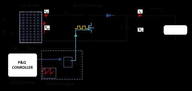
Step-3: the time located to switching devices is calculated. As seen in Table (3), the, whole
swtiching slot Tz can be divided into 7 parts by applying the zero, state vector of the first, part to
the 1/4 ℎ from state time. In the 2nd and 3rd parts of the time, apply the active state vector to half
of the total time for the vector, then the 1/4 ℎ zero of the state vector slot. This sequence is repeated
during the switching period. [17].
 Table 3. Switching time for each sector

5. Simulink model design
 The PV Simulink model including the P & Q controller, based on MPPT, is shown in Figure 7.
Optimal PV systems include PV panels, boost converters with MPPT algorithms, and inverters. The
basic purpose of the MPPT is to adjust ‘the convertor duty cycle. This allows the converter to
provide maximum power to the inverter at, any irradiance and temperature. Boost convertor
impedance gives the requirement to maximize maximum power) is determined using, the following,
equation [12]:
 = (1 − )2 (15)
 To keep the output impedance constant, MPPT technology is used to change the duty cycle so
that the source input impedance shown is equal to the full load impedance. By training and
optimizing the parameters of the P & Q controller, we will get the best output in terms of minimum
average error. The output of the P & Q controller is then validated to the high; frequency carrier
signal to obtain the desired duty-cycle that synchronized with with changing weather conditions
[18].
Figure 7. The PV‘model with a P&Q controller.

 Figure 8. The PV system model with a P&Q controller.

6. Simulation Results
 As shown in Figure 8, the PV system with the P & Q controller MPPT method and an SVPWM
control scheme for a 3-phase power pulse width modulation inverter is implemented in the Matlab
/ Simulink software package. The Simulink model of the PV module is designed according to the
mathematical formulas is shown in Figure 9. The Kyocera Solar KD215GX-LPUPV module has
the characteristics shown in Table (1) and consists of 72 polycrystalline silicon solar cells. The
Simulink models of the boost converter are illustrated in Figure 10 [3]. The boost converter
inductance and capacitor values are 0.01MH and 700µF respectively while the output load value is
78 ohms. The complete Simulink model of a 3-phase power supply PWM inverter and the SVPWM
control method is shown in Figure 8.
Figure 9. The PV system model

 Figure 10. The Boost’converter model

 Using arbitrary values of temperature and irradiance supplied to the solar panel, it is necessary
to calculate the value of input impedance in order ’to get the MPPT after choosing the optimsed
input resistance value for the total probability of sun temperature and irradiance. By fixing the output
impedance to 78 ohms, the value of duty ratio D can be calculated using equation (15). The
temperature values are:25℃, and 50 ℃ and the irradiance is changing as 600 ⁄ 2 ., 800 ⁄ 2 .,
and 1000 ⁄ 2 . ‘The duty ratio supplied to the boost converter for maximum power at all
temperatures and irradiance values should be optimum. The values of irradiance and .temperature
are used as inputs for training’ data’ of P & Q control, the desired output is the duty cycle. The
operation test of the Photovoltaic system in simulation including the Photovoltaic system response,
The outputs of the boost converter under different values in irradiance are shown in Figures
11,12,13,14,15, and 16, and temperature are shown in Figures 17, 18, and 19. For example, If the
load is connected directly to the PV panel at T = 25 ° C, G = 103 ⁄ 2 and the power is 213.9
Watts, while the power 202.5 W when connected to PV via a boost’ converter. Therefore, the P &
Q controller is efficient at extracting MPPT in the context of temperature and irradiation changes.

 Figure 11. The output current response for boost’ converter T =25 ℃

 Figure 12. The output voltage response for boost’ converter T =25 ℃

 Figure 13. The output power response for boost’ converter T =25 ℃
Figure 14. The output current response for boost’ converter T =50 ℃

Figure 15. The output voltage response for boost’ converter T =50 ℃

Figure 16. The output power response for boost’ converter T =50 ℃
Figure 17. The output current response for boost’ converter at changing Temperature at G=1000 ⁄ 2

 Figure 18. The output voltage response for boost’ converter at changing Temperature at G=1000
 ⁄ 2

Figure 19. The output power response for boost’ converter at changing Temperature at G=1000 ⁄ 2
The output of the SVPWM is produced from the Simulink model illustrated in Figure 20 in which
including positioning the based on the f = 50 Hz, and fs = 10 kHz. Figure 21 shows a Simulink
diagram of the switching time of the SVPWM pulse waveform. It can be seen that the shape of the
inverter output voltage is determined depending on the modulation index.

 Figure 20. The Simulink block diagram for SVPWM

 Figure 21. The simulation block diagram for switching time

 The output voltages of SVPWM in case of T = 25 °C and G= 1000 ⁄ 2 is shown in Figure
22. The output voltages of SVPWM in case of changing the irradiance at T = 25°C are shown in
Figure 23 and the output voltages at T = 50 °C are shown in Figure 24. The whole output voltage
based on Harmonic Distortion is seen in Figure 25.
Figure 22. The output voltage for G=1000 w/m2 and T=25℃

Figure 23. The output voltage for various different irradiation at T=25℃

 Figure 24. The output voltage for various irradiation at T=30℃
Figure 25.The THD of output line voltage for space vector pulse width modulation

7. Conclusion
 The stand-alone Photovoltaic power generation system has been proposed. The design depends
on the (P & Q) MPPT and SVPWM methods for a 3-phase PWM inverter. The P & Q MPPT
algorithm is implemented in Matlab / Simulink. The simulation results show that the P&Q MPPT
algorithm can simultaneously get better performance of the dynamic and steady-state performance
of Photovoltaic systems. At the same time, the output result of the inverter using the SVPWM has
improved power quality. The results also show that the proposed Photovoltaic system has a reliable
and effective response under variation atmospheric conditions. Therefore, a stand-alone
Photovoltaic power generation system based on the P & Q MPPT method for a 3-phase voltage
source pulse width modulation inverter and SVPWM control is practical and effective. The designed
system produces the ability to operate at lower switching frequencies with less dv/dt the voltage
stress on the switching device. Space vector pulse width modulation is the best selection of inverter
switching states that improves the DC link voltage employment. This outperform other traditional
pulse width modulation methods.

References:
[1] A. Pandey, N. Dasgupta, and A. K. Mukerjee, “High-performance algorithms for drift
 avoidance and fast tracking in solar MPPT system,” IEEE Trans. Energy Convers., vol. 23,
 no. 2, pp. 681–689, 2008, doi: 10.1109/TEC.2007.914201.
[2] P. Shaw, “Modelling and analysis of an analogue MPPT-based PV battery charging system
 utilising DC-DC boost converter,” IET Renew. Power Gener., vol. 13, no. 11, pp. 1958–
 1967, 2019, doi: 10.1049/iet-rpg.2018.6273.
[3] W. I. Hameed, A. L. Saleh, B. A. Sawadi, Y. I. A. Al-Yasir, and R. A. Abd-Alhameed,
 “Maximum power point tracking for photovoltaic system by using fuzzy neural network,”
 Inventions, vol. 4, no. 3, 2019, doi: 10.3390/inventions4030033.
[4] B. M. Hasaneen and A. A. E. Mohammed, “Design and simulation of DC/DC boost
converter,” 2008 12th Int. Middle East Power Syst. Conf. MEPCON 2008, pp. 335–340,
 2008, doi: 10.1109/MEPCON.2008.4562340.
[5] M. Chen and D. Sun, “A unified space vector pulse width modulation for dual two-level
 inverter system,” IEEE Trans. Power Electron., vol. 32, no. 2, pp. 889–893, 2017, doi:
 10.1109/TPEL.2016.2585223.
[6] H. C. Lu and T. L. Shih, “Design of DC/DC boost converter with FNN solar cell maximum
 power point tracking controller,” Proc. 2010 5th IEEE Conf. Ind. Electron. Appl. ICIEA
 2010, no. 1, pp. 802–807, 2010, doi: 10.1109/ICIEA.2010.5515085.
[7] A. M. Dakhil, A. R. Hussein, and A. L. Saleh, “Transformer-less Single-phase Inverter
 Based on SPWM Technique for Standalone PV Application,” Solid State Technol., vol. 63,
 no. 3, pp. 4088–4101, 2020.
[8] P. K. Pathak and A. K. Yadav, “Design of battery charging circuit through intelligent MPPT
 using SPV system,” Sol. Energy, vol. 178, no. July 2018, pp. 79–89, 2019, doi:
 10.1016/j.solener.2018.12.018.
[9] S. Wadhankar and B. Charjan, “Design and Simulation of Photovoltaic Water Pumping
 System,” no. September, pp. 83–92, 2019, doi: 10.1007/978-981-13-6148-7_9.
[10] M. A. Eltawil and Z. Zhao, “MPPT techniques for photovoltaic applications,” Renew.
 Sustain. Energy Rev., vol. 25, pp. 793–813, 2013, doi: 10.1016/j.rser.2013.05.022.
[11] V. Janaki Ramaiah and S. Keerthipati, “Hybrid PWM Scheme for Pole-Phase Modulation
 Induction Motor Drive Using Carrier-Based Hexagonal and Octadecagonal SVPWM,”
 IEEE Trans. Ind. Electron., vol. 67, no. 9, pp. 7312–7320, 2020, doi:
 10.1109/TIE.2019.2946537.
[12] S. J. Yaqoob, A. Raisan Hussein, and A. L. Saleh, “Low Cost and Simple P&O-MPP
 Tracker Using Flyback Converter,” no. November, 2020, [Online]. Available:
 www.solidstatetechnology.us.
[13] M. Valan Rajkumar, P. S. Manoharan, and A. Ravi, “Simulation and an experimental
 investigation of SVPWM technique on a multilevel voltage source inverter for photovoltaic
 systems,” Int. J. Electr. Power Energy Syst., vol. 52, no. 1, pp. 116–131, 2013, doi:
 10.1016/j.ijepes.2013.03.022.
[14] S. Chatterjee, “A multilevel inverter based on SVPWM technique for photovoltaic
 application,” Int. J. Power Electron. Drive Syst., vol. 3, no. 1, pp. 62–73, 2013, doi:
 10.11591/ijpeds.v2i4.403.
[15] A. M. Nazlee, N. H. Hamid, F. A. Hussin, and N. B. Z. Ali, “Space Vector PWM for PMSM
 simulation using Matlab Simulink,” IEEE Asia-Pacific Conf. Circuits Syst. Proceedings,
 APCCAS, pp. 1127–1130, 2010, doi: 10.1109/APCCAS.2010.5774974.
[16] K. A. Chinmaya and G. K. Singh, “Experimental analysis of various space vector pulse
 width modulation (SVPWM) techniques for dual three-phase induction motor drive,” Int.
 Trans. Electr. Energy Syst., vol. 29, no. 1, pp. 1–15, 2019, doi: 10.1002/etep.2678.
[17] K. Agrawal, A. Gandhi, M. T. Shah, and M. V. Gojiya, “Design, analysis and realization of
 SVPWM using embedded code generation technique for a three phase, two level inverter,”
 Int. Conf. Electr. Power Energy Syst. ICEPES 2016, pp. 377–382, 2017, doi:
 10.1109/ICEPES.2016.7915961.
[18] W. I. Hameed, B. A. Sawadi, and A. M. Fadhil, “Voltage tracking control of DC-DC boost
 converter using fuzzy neural network,” Int. J. Power Electron. Drive Syst., vol. 9, no. 4, pp.
1657–1665, 2018, doi: 10.11591/ijpeds.v9n4.pp1657-1665.
You can also read