Medical Resistors RESISTORS APPLICATION NOTE - TT Electronics
←
→
Page content transcription
If your browser does not render page correctly, please read the page content below
RESISTORS APPLICATION NOTE

    Medical Resistors

TT Electronics reserves the right to make changes in product specification without notice or liability.   www.ttelectronics.com
All information is subject to TT Electronics’ own data and is considered accurate at time of print.       Issue A      08/2021
© TT electronics plc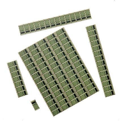
Resistors Application Note
Medical Resistors

                                                      Resistors For Medical Applications

The electronic content of devices for medical applications continues to rise
steadily as medical science develops new techniques and electronic
engineering supplies new solutions. At the same time, these devices are
leaving the confines of hospitals and serving the growing community-based
and home-based healthcare markets.

Much of the development is based on the increasing computing power of
digital systems. However, the human body remains analogue, and there will
always be an important role for high reliability passive components in three
broad areas:
•         CONTACT
•         IMAGE
•         ANALYSIS

The first area, CONTACT, includes all devices with electrical                        • High-voltage compact solutions for defibrillator
connection to the body. Examples include the delivery of high                            charge control
energy pulses for defibrillation, the detection of biologically                      •   Pulse withstanding resistors for defibrillation pulse
generated signals for ECG or EEG and the measurement of body                             protection
impedance for respiratory or plethysmographic monitoring.
                                                                                     •   High ohmic value parts for high gain amplifiers in ECG
The IMAGE area encompasses X-ray, MRI and ultrasound, all                                and similar monitors
with their own special demands on resistive components.                              •   Ultra high-voltage resistors for X-ray head supply
Finally, ANALYSIS covers the area of IVD and laboratory instru-                          dividers
ments.                                                                               •   Thin-film termination networks for ultrasound
                                                                                         transducers
This application note aims to guide the designer in selecting the                    •   Non-magnetic resistors for MRI scanners
optimum components for all these areas. It should be read in                         •   Precision resistors for high stability in IVD analysis
conjunction with the full product data sheets.                                           equipment

For our full product portfolio, in-house & local design support / distribution partners, visit:
https://www.ttelectronics.com/products/categories/passive-components/

General Note
                                                                                                             TT Electronics | BI Technologies IRC Welwyn
TT Electronics reserves the right to make changes in product specification without
                                                                                                                                       www.ttelectronics.com
notice or liability. All information is subject to TT Electronics’ own data and is
considered accurate at time of going to print.
© TT electronics plc                                                                                                             Issue A   08/2021 Page 2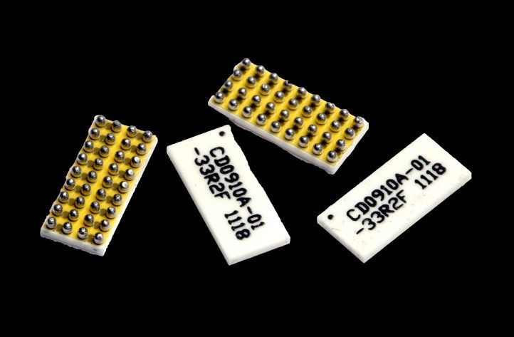
Resistors Application Note
Medical Resistors

                                                     Contact: Defibrillator Charge Control
A simplified schematic of a defibrillator charge circuit is shown in Figure 1. The stable and repeatable measurement of the
charging voltage is a critical function of this circuit, as this determines the amount of electrical energy delivered to the
patient. As the energy delivered is proportional to the square of the voltage, a 1% tolerance requirement for the energy will
demand a 0.5% tolerance on the voltage control.

                                                           Change Circuit                          Discharge Circuit
                                                                                     2— 5kV

                                                                                     R1
                          High Voltage                                                                          Patient
                                                              Voltage
                             Supply                           Feedback                                          Paddles
                                                                                     R2

     Figure 1

In this circuit R1 is a high value resistor, normally in the range 5M to                  coefficients of resistance, which are limits on the reversible
50M, which, together with a commodity chip resistor R2, forms a                           resistance changes illustrated in Figure 2. The temperature
potential divider for voltage feedback.                                                   characteristic is normally “U” shaped with limits expressed by
                                                                                          the TCR, which is typically ±100ppm/ºC. The TCR error may be
The critical features of this high voltage resistor are linearity,                        minimized by choosing the highest possible ohmic value so as to
expressed by voltage coefficient (VCR) and temperature coefficient                        reduce the self heating, and by a layout which avoids proximity to
(TCR), and long term stability under voltage stress. In addition to                       heat generating components.
this, the rapid growth in the non-professional AED segment adds
the requirement for compact footprint and suitability for a wider                         The voltage characteristic, by contrast, only has a negative
range of environmental conditions, including high humidity. The                           gradient, with a limit expressed by the VCR, which is typically
error budget for resistance value can be expressed as:                                    -1 to 5ppm/V. High voltage resistors use special design techniques
                                                                                          to minimize VCR, but ultimately there is a trade-off between VCR
Error = Tolerance + Solder heat stability + TCR error at                                  and product size. It should be noted that, as the gradient increases
Tmin / Tmax + VCR error at Vmax + Environmental Stability                                 at high voltage, VCR error can be reduced by only operating the
                                                                                          resistor at up to 75% of the full rated voltage. Resistors are
The first two terms are commonly eliminated by post-assembly                              normally adjusted and measured at voltages Vmeasure 100V, but
calibration. The remaining three are described in detail below.                           TT Electronics can also supply resistors with an adjustment offset
                                                                                          which minimizes the VCR error at a given higher nominal operating
The resistor technology best suited to this application is thick-film.                    voltage.
The linearity limits are expressed as the temperature and voltage

                                    Typical Temperature and Voltage Characteristics for Thick-Film Resistors
                                                  Resistance                                   Resistance
                                                   Change                                       Change
                                                                           TCR (+ve)

                                                                            Temperature                                      Voltage
                                              Tmin                  Tmax                                              Vmax
                                                          25°C                                       Vmeasure

     Figure 2                                                             TCR (-ve)                                   VCR (-ve)

General Note
                                                                                                                        TT Electronics | BI Technologies IRC Welwyn
TT Electronics reserves the right to make changes in product specification without
                                                                                                                                                  www.ttelectronics.com
notice or liability. All information is subject to TT Electronics’ own data and is
considered accurate at time of going to print.
© TT electronics plc                                                                                                                        Issue A   08/2021 Page 3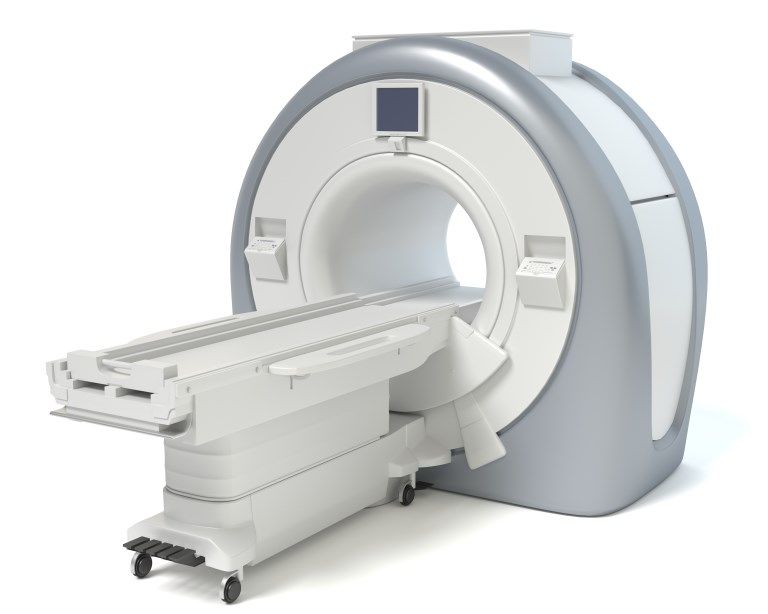
Resistors Application Note
Medical Resistors

                                             Contact: Defibrillator Charge Control (Cont.)
The environmental stability describes the limits of non-reversible resistance change under given loading and environmental
conditions. The most demanding condition is high humidity, but TT Electronics optionally seals the resistive element using a
specially formulated powder coat material to achieve typical resistance changes within ±0.1% on both Moisture Resistance
and Biased Humidity tests.

High Voltage Planar SIL Resistors                                                        High Voltage Chip Resistors

HVP Series                                                                               HVC Series

• Compact design with minimal                                                            •      Standard SMD chip format
      footprint                                                                          •      Continuous rating to 3kV
•     Sealed by high-density epoxy protection                                            •      Low voltage coefficient
•     Low TCR and VCR                                                                    •      Tolerance to ±0.5%
•     Leadframe standoff permits thorough washing                                        •      TCR to ±50ppm/°C
•     Custom sizes, ratings and HV screening
•     Integrated divider version available as HVD Series
•     Optional powder coated version

 Electrical Data HVC Series & HVP Series                          HVC1206             HVC2010       HVC2512        HVP                       Notes
 Power rating @70°C                                  watts            0.3               0.5             1         0.4 - 2
 Limiting element voltage                             volts          1000               2000          3000     2000-20,000
                                                                                                                                        DC or AC peak
 Overload voltage (2s)                                volts          1500               3000          4000
 Resistance range                                    ohms                            10K to 1G                  1K to 10G         Consult factory for out
                                                                                                                                     of range values
 Resistance tolerance                                    %                       0.5, 1, 2, 5, 10              0.25,0.5,1,5      See datasheet for appli-
 TCR                                             ppm/°C                               50, 100                   25,50,100          cable value ranges

 Ambient temperature range                               °C                                   -55 to + 155
 Values                                                                                E24 & E96 preferred                           Any value to order
 VCR                                              ppm/V               -15                -5            -1.5     -0.5 to -1                   Typical
 Further data                                                                        Datasheet                  Datasheet

General Note
                                                                                                                     TT Electronics | BI Technologies IRC Welwyn
TT Electronics reserves the right to make changes in product specification without
                                                                                                                                               www.ttelectronics.com
notice or liability. All information is subject to TT Electronics’ own data and is
considered accurate at time of going to print.
© TT electronics plc                                                                                                                     Issue A   08/2021 Page 4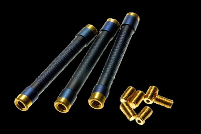
Resistors Application Note
Medical Resistors

                                                  Contact: Defibrillator Pulse Protection
The possibility of exposure to defibrillation pulses exists for any directly connected monitors, and it is necessary to guard
against damaging the sensitive input stages of such equipment. It is even more important to avoid diverting the defibrillation
energy from the patient. This is achieved by adding resistance to the monitor input circuit, usually in the form of a pulse
withstanding resistor. This is built into the leadset, either at the probe connector or in the yoke where the single cable breaks
out into individual probe leads. Additional protection may be provided within the monitor itself. The standard test circuits
are shown in Figure 3.
                                  AAMI EC 53 Test Circuit                                               IE C601 Test Circuit

              Defib              400R                R1                                Defib           50R             R1
             Contact                                                                  Contact
                            100R                                                                 100R
                                                              R2 R3       Rn                                                    R2 R3       Rn

  Figure 3
                         Body Model               Leadset                                       Body Model          Leadset

 The proportion of the total defibrillation energy received by                       TT Electronics can advise on the exact energy rating
 a protection resistor depends on its ohmic value, and the                           required, but 25J at 1K falling to 2.5J at 10K are typical
 highest value consistent with monitor function should be                            values for leadset protection, and this calls for a
 used to minimize this. There is also a variation depending on                       composition technology product such as CC series. For
 which test circuit is used, and, in the case of IEC601, on how                      PCB mounted resistors offering secondary protection,
 many leads are in the leadset.                                                      pulse withstanding thick-film products such as PWC, DSC
                                                                                     and DPCR series are used.

 High Energy Composition Resistors                                                   Pulse Withstanding Chip Resistors

 CC Series                                                                           PWC, DSC & DPCR Series

 • Carbon composite element                                                          • Standard SMD chip with
 • Energy rating to 30J                                                                  guaranteed pulse performance
 • High voltage epoxy coating                                                        • Defibrillation pulse chip resistor DPCR
                                                                                     • DSC is double sided for double energy capacity

  Electrical Data CC, PWC, DSC & DRCR                                    CC Series           PWC2512                 DSC2512                  DPCR2512
  Series
  Power rating                                         watts                1&2                  1.5                     1.5                       1.5

  Energy rating (10ms pulse)                            volts             20 to 30               1                          2                       4
  Resistance range                                    ohms              100R - 50K           1R - 10M                1R - 4M7                 20K - 100K
  Resistance tolerance                                    %                 10, 20                      0.5, 1, 5                                   5
  Further data                                                           Datasheet          Datasheet                Datasheet                Datasheet

General Note
                                                                                                                    TT Electronics | BI Technologies IRC Welwyn
TT Electronics reserves the right to make changes in product specification without
                                                                                                                                              www.ttelectronics.com
notice or liability. All information is subject to TT Electronics’ own data and is
considered accurate at time of going to print.
© TT electronics plc                                                                                                                    Issue A   08/2021 Page 5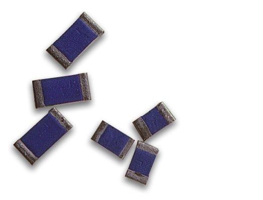
Resistors Application Note
Medical Resistors

                                                   Contact: ECG High Gain Amplification
Where ECG monitors and analytical instruments require sensitive first stages for amplification of small signals, high ohmic
values are required in the feedback resistor (Figure 4). TT electronics has long specialized in providing values outside the
range normally available, with some specialist products extending to 100TΩ (1014Ω). These are glass sealed resistors with
the option of a guard-band for mitigation of leakage effects. In the flat chip format values extend to 50G and special sizes are
available to minimize shunt capacitance and capacitance to ground plane.

                                                                               R3

                                                                                          R1
                                                                                     R2
                                                                                                             G = (R1 + R2) / R2
     Figure 4

Ultra-High Value Resistors                                                                High Value Chip Resistors

3810 Series                                                                               HR Series

• Values up to 100T                                                                       • Standard SMD chip up to 50G
• Precision to 1% at 1T                                                                   • Precision to 5% at 1G
• Silicone coated glass body                                                              • Solder or wire bond terminations

  Electrical Data 3810 Series & HR Series                                3810                  3811            3812             HR0805               HR1206
  Resistance range                                   watts                      100M - 1T                    1T - 100T                100M to 50G
  Limiting element voltage                            volts               500                         1000                         100                 200
  Further data                                                                            Datasheet                                     Datasheet

General Note
                                                                                                                      TT Electronics | BI Technologies IRC Welwyn
TT Electronics reserves the right to make changes in product specification without
                                                                                                                                                www.ttelectronics.com
notice or liability. All information is subject to TT Electronics’ own data and is
considered accurate at time of going to print.
© TT electronics plc                                                                                                                      Issue A   08/2021 Page 6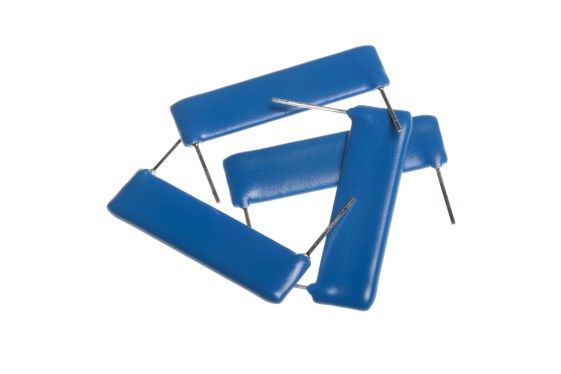
Resistors Application Note
Medical Resistors

                                                                    Image: X-Ray Supply
 X-ray systems require stable and accurate high voltage                                 such as HVP Series (see Page 4 for data) which provides up
 supplies to provide the accelerating voltage for X-ray                                 to 20kV per element. Another solution is to use T Series axial
 generation. Voltages are typically in the 50kV to 100kV                                resistors which provide up to 100kV in a single element in an
 range, and the circuit is often assembled in an oil-filled                             oil-filled or SF6-filled assembly. Terminations are either wire
 chamber. This reduces clearance and creepage constraints                               or screw, allowing easy stacking into multiple resistor
 on the components and layout, thus enabling a compact                                  assemblies. In order to eliminate the possibility of air
 X-ray head design.                                                                     pockets the unsleeved version (pictured) should
                                                                                        be selected. It is possible to supply these parts in matched
 TT Electronics has extensive experience of supplying                                   sets to give accurate ratio tolerance or to give very low TCR
 ultra-high voltage thick-film solutions for voltage division in                        by means of cancellation. Finally, custom divider networks
 this application and can supply various standard and custom                            can be designed with track layouts and component outlines
 formats. One design approach is to use a series combination                            which give optimized solutions for highly compact head
 of high voltage resistors                                                              designs.

Ultra-High Voltage Resistors                                                            Custom Resistor & Divider Networks

T Series
                                                                                        • Good ratio tolerance and TCR tracking
•     LEV to 100kV                                                                      • Optimized size and shape
•     Values up to 50G                                                                  • Ideal for compact head designs
•     Precision to 0.5% 25ppm
•     Matched sets available

  Electrical Data T Series                                         T43                    T44                  T48                          Notes
  Limiting element voltage                       volts       4000 / 8000             14,000 / 28,000    50,000 / 100,000
                                                                                                                                        In air / in oil
  Power rating @20°C                            watts           1.5 / 2.3               3.5 / 5.3            10 / 15
  Resistance range                              ohms                                     1K to 50G
  Tolerance                                         %                                      1, 2, 5                              0.5% in restricted range
  TCR                                       ppm/°C                                      25, 50, 100
  Further data                                                                           Datasheet

General Note
                                                                                                                     TT Electronics | BI Technologies IRC Welwyn
TT Electronics reserves the right to make changes in product specification without
                                                                                                                                               www.ttelectronics.com
notice or liability. All information is subject to TT Electronics’ own data and is
considered accurate at time of going to print.
© TT electronics plc                                                                                                                     Issue A   08/2021 Page 7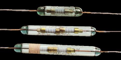
Resistors Application Note
Medical Resistors
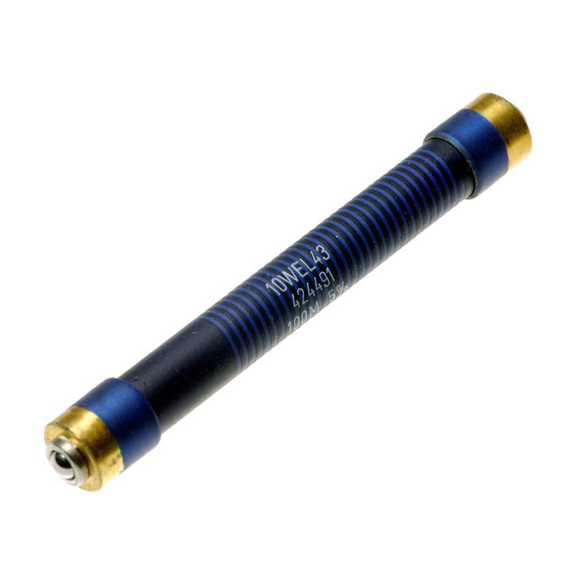
Image: Medical Scanners
Ultrasound transducers require termination networks MRI scanners require control circuits which are insensitive
capable of operating at high frequency and providing to extremely high magnetic field strengths, and this calls for
multiple channels of resistive termination. A typical components which are free of ferrous alloys and nickel.
requirement is 128 channels and performance up to 15MHz. These are the materials commonly used in the termination
TT Electronics can provide standard and custom thin-film caps fitted to the ends of most types of axial resistor and as
resistor networks in a wide variety of packaging styles an anti-leaching barrier in chip resistors. TT Electronics can
including SOIC, QSOP, TSSOP. The latest addition is a BGA supply the non-magnetic glueable chip, GCR Series, for this
part which can offer up to 32 terminators in a 6.4 x 2.5mm requirement.
footprint with return loss below -20dB to 3GHz. This meets
the requirement above within the space of four 2512 chips.
BGA Network Non-Magnetic Chip Resistors
Analysis: Precision Resistors
For a broad range of laboratory analysis equipment, the best available precision. Secondly, SMD thin-film
Precision resistors are required with tight tolerance, low products with multiple elements provide a combination of
temperature sensitivity and high stability. The input stage of high precision and a compact single-component solution.
an instrument with a resistive sensor, for example a
thermistor in a precision temperature monitoring circuit, The precision through-hole resistor offering ranges from
consists of a bridge of resistors which must be closely semiprecision PR Series through the popular precision RC
matched in value (Figure 5). In such a case it is the ratio Series to ultraprecision MAR which matches the perfor-
between values which matters rather than the absolute mance of costly metal foil technology using advanced metal
Values themselves. Likewise, the maximum difference be- film techniques. The precision SMD offering includes con-
tween TCRs, that is the tracking TCR, is more important than ventional thin-film chip resistors using nichrome elements as
the absolute TCR. TT Electronics can offer two solutions in well as ultra high stability versions which exploit the self-
these cases. Firstly, most through-hole precision resistors passivating properties of tantalum nitride film (WIN Series).
are available in matched sets with specified ratio tolerance
and tracking TCR, and this solution gives
V+
R1 R2 Difference
amplifier
R3 Rt
Wheatstone
Figure 5 bridge
General Note
TT Electronics | BI Technologies IRC Welwyn
TT Electronics reserves the right to make changes in product specification without
www.ttelectronics.com
notice or liability. All information is subject to TT Electronics’ own data and is
considered accurate at time of going to print.
© TT electronics plc Issue A 08/2021 Page 8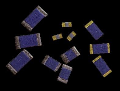
Resistors Application Note
Medical Resistors

                                                    Analysis: Precision Resistors (Cont.)

       Format                 Product              Absolute      Ratio     Absolute   Tracking                       Further Data
                                                  Tolerance % Tolerance % TCR ppm/°C TCR ppm/°C
                                  PR                    0.1
                                                                                     25
                                                                                                                       Datasheet
                                RC                      0.05                0.02
                            0.25 to 1W                                               5             2
                                                                                                                       Datasheet
                                RCP                     0.05                 0.02    5             2
  Through-hole              0.5 to 1.5W
                                                                                                                       Datasheet
                               CAR                      0.01                0.005    5             1
                           0.25 to 0.5W
                                                                                                                       Datasheet
                                MAR                    0.005                0.005    2             1
                                0.3W
                                                                                                                       Datasheet
                                PCF                     0.1                          10
                              0.063 to
                               0.25W                                                                                   Datasheet
                                WIN                     0.05                         15
         SMD               0.1 to 0.33W
                                                                                                                       Datasheet
                           PFC-DIVIDER                                       0.02                  5
                           0.25W total
                                                                                                                       Datasheet

 * For through-hole parts, applies to matched sets

 For our full product portfolio, in-house & local design support / distribution partners, visit:
  https://www.ttelectronics.com/products/categories/passive-components/

General Note
                                                                                                       TT Electronics | BI Technologies IRC Welwyn
TT Electronics reserves the right to make changes in product specification without
                                                                                                                                 www.ttelectronics.com
notice or liability. All information is subject to TT Electronics’ own data and is
considered accurate at time of going to print.
© TT electronics plc                                                                                                       Issue A   08/2021 Page 9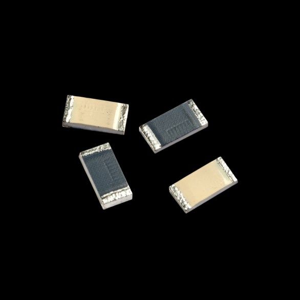
You can also read