A Survey on SQM for Sat-Nav Systems - International Journal of Science and Research (IJSR)
←
→
Page content transcription
If your browser does not render page correctly, please read the page content below
International Journal of Science and Research (IJSR)
ISSN (Online): 2319-7064
Index Copernicus Value (2013): 6.14 | Impact Factor (2013): 4.438
A Survey on SQM for Sat-Nav Systems
Sudarshan Bharadwaj DS
Department of ECE, Cambridge Institute of Technology, Bangalore
Abstract: Reduction of multipath effects on the satellite signals can be accomplished with innovative hardware design. Although such
methods are effective in reducing multipath and the effects due to it, they are not practical enough, especially in varying environmental
conditions. Implementation of Narrow Correlator spacing technique can reduce multipath effects to a great extent but has no advantage
over carrier phase measurement accuracy. Pulse Aperture Correlator (PAC) although takes full advantage over Narrow correlator
technique, it has low Signal to Noise ratio (SNR) and cannot remove close-in multipath. This paper provides an overview of early
performance results obtained by using different correlator techniques for monitoring the quality of satellite signals. This paper proposes
implementation of Vision Correlator for Signal Quality Monitoring of satellite signals. Vision Correlator is particularly useful in
removing close-in multipath and also mitigates the effects of multipath on the signals in the line of sight. An experimental setup to check
for the performance of Vision Correlator against the standard correlator has been proposed. Further, IRNSS architecture and frame
format have been discussed.
Keywords: IRNSS, SQM, PRN CODE, SHAPE, MMT, ICD, SPS, TLM, TOWC, CRC, MMT.
1. Introduction reference receiver which will warn its users of potentially
hazardous misleading information (HMI) within the Time to
Navigation is a process of monitoring and controlling the alarm (for avionics applications this is 6 seconds). This
movement of a space vehicle from one place to another. The monitoring scheme is called SINGAL QUALITY
location of vehicles will be determined based on the latitude MONITORING.
(equator) and longitude (prime meridian) values. For e.g. the
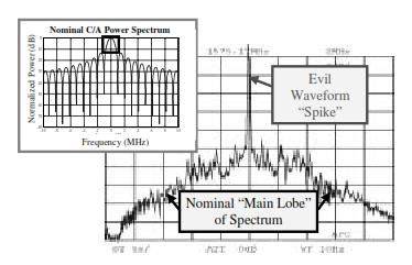
latitude and longitude values of India is 22°00’N E.g. Signal anomaly on GPS Satellite SV19, observed in
77°00’E.The Indian Standard Timings (IST) is calculated OCTOBER 1993.It caused differential pseudorange errors
based on 82.5°E longitude. Based on these latitude and on the order of 3 to 8 meters. Figure1 shows the signal
longitude values, the location of a vehicle can be anomaly observed due to the satellite hardware failure.
determined.
Following lists the different Navigation systems in use:
1) Automotive Navigation Systems.
2) Marine Navigation Systems.
3) Global Positioning Systems (GPS).
4) GPS Navigation Device.
5) Robotic Mapping Device.
The Global Positioning System; introduced by the U.S
Department of Defense in 1973, whose original purpose was
to provide accurate navigation and time transfer to
military users. In the past decade there has been a rapid [1]
Figure 1: SV19 Signal Power Spectrum
growth in GPS civilian applications, which includes
farming, marine, surveying and recreation purpose as well. Why SQMSignal anomaly occurs due to the failure of
satellite or due to the failure of hardware at the receiver end.
In concurrence with specially designed equipment on the These anomalies will raise a distortion in the correlation
ground, GPS can provide precision approach and landing curve resulting in a large positioning error. Hence; a
capability for aircrafts. However, in 1993 due to the monitoring scheme is needed to check for these anomalies
malfunctioning of one of the satellites, significant amount of prior to sending this information to SAT-NAV
distortion was introduced onto one of the pseudorandom systems.SQM also protects the receivers from signal
(PRN) codes. This caused a large pseudorange error. anomalies in the presence of multipath.
Signals that are received from the satellites might not always The SQM scheme would consist of one or more receivers
be clean. There could possibly be many anomalies in the having several correlators to sample the correlation peak at
signal. Anomalous signals are result of data transmission or various locations to determine the level of distortion. An
hardware failures at or on the satellite itself. In addition to effective SQM design would keep the maximum differential
this, signal anomalies are also due to multipath, scintillation pseudorange error below the maximum allowable error
errors, Tropospheric and Ionospheric delays. In order to (MERR) in par with the elevation angles.
maintain the stringent integrity requirements of Wide area
augmentation systems and large area augmentation systems,
some kind of monitoring scheme needs to be in place at the
Volume 4 Issue 5, May 2015
www.ijsr.net
Paper ID: SUB154348 1229
Licensed Under Creative Commons Attribution CC BY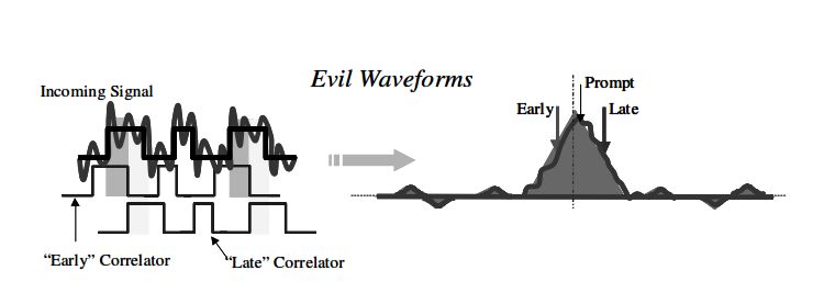
International Journal of Science and Research (IJSR)
ISSN (Online): 2319-7064
Index Copernicus Value (2013): 6.14 | Impact Factor (2013): 4.438
2. Threats to Satellite Signal Quality Although many attempts were made to improve the receiver
performance using different correlator technologies, narrow
1) Evil waveforms (EWF): correlator technology is proven to be more efficient and
EWF are due to the signal generating hardware failure. many of the receivers for sat-nav applications still make use
These failures introduce anomalous distortions onto the of the same.
correlation peak (figure2). If such distortions are present on
a satellite signals being tracked by a receiver; this could Narrow Correlator technology plays a very vital role in
pose a severe threat to the integrity of that airborne user. eliminating multipath error and while tracking the PRN code
it reduces the code tracking errors in the presence of
multipath. But, Narrow correlator spacing method has no
advantage in terms of carrier phase measurement accuracy.
Wider precorrelation bandwidth is required with higher
sampling and DSP rates which has to be overcome with
CMOS techniques. With all these advancements the bias due
to multipath in GPS position calculations is still dominant.
PAC tracking loop is advantageous over narrow correlator
spacing design. Additionally, PAC provides greater
[1] resistance to the multipath effects on the correlation function
Figure 2: Effect of Evil Waveform on code tracking and reduces multipath bias on the pseudorange
measurements. But, PAC has very low SNR and can’t
2) MULTIPATH remove close-in multipath. Hence, another new correlator
It causes significant distortion to the correlation peak technology called VISION CORRELATOR has been
(Figure3).The multipath is the reduced amplitude copy of introduced to reduce the effect of multipath on the signal.
the original signal. Since the relative delay, amplitude and
multipath parameters are generally unknown; the VISION CORRELATOR is a method of measuring and
superposition of these signals produces an unknown processing synchronization signals of a received PRN code.
distortion of correlation peak. It’s very much useful in removing the close-in multipath.
Vision Correlator measures the phase transitions of
modulated signal broadcasted from Satellite; measures the
radio frequency characteristics of this broadcasted signal in
time domain. It provides a very useful static that can be used
for Signal Quality Monitoring of the received signal. This
static is very much useful in filtering the unrepairable data.
Following Figure4 illustrates the baseband in-phase channel
Figure 3: Effect of multipath on code tracking [1] signal modulation in time domain during a sequence of PRN
codes.
To reduce these threats on the satellite signal and to improve
the quality and maintain the receiver integrity several
correlator technologies have been implemented such as:
1) Narrow Band Correlator.
2) Wide Band Correlator.
3) Pulse Aperture Correlator (PAC).
4) Vision Correlator.
Importance of CORRELATIONCorrelation is a
statistical measure that indicates the extent to which two or
more variables fluctuate together. Correlation analysis is one
of the most widely used and reported statistical method in
summarizing research data. Figure 4: Time domain simulation of the in-phase channel
[3]
of a GPS receiver.
Correlation does not make any prior assumption about the
dependency and relationship between the variables. If two We can generate Vision Correlator output by filtering all
variables are perfectly correlated then we can predict the transitions over a period of time. A “shape” can be
value of one variable by making use of the other. It also extracted from all the transitions. Figure5 shows average bit
checks for the interdependency of the variables. transition shape as measured from a specific satellite and
GPS receiver.
Correlators are the key operation for navigation system
receivers to synchronize with incoming signal and retrieve
navigation message that will be used to provide navigation
solution.
Volume 4 Issue 5, May 2015
www.ijsr.net
Paper ID: SUB154348 1230
Licensed Under Creative Commons Attribution CC BY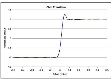
International Journal of Science and Research (IJSR)
                                              ISSN (Online): 2319-7064
                            Index Copernicus Value (2013): 6.14 | Impact Factor (2013): 4.438

                                                                                                               [3]
                                                                            A:Output of standard Correlator

 Figure 5: Avg chip transitions of GPS PRN 1 as measured
      using NovAtel ME3 GNSS receiver (VISION
                                              [3]
         CORRELATOR MEASUREMENTS)

Vision Correlator filters noise by overlapping chip
transitions over a period of time and to get average chip
transitions. This average chip transitions gives us Vision
samples (shape). These vision samples are later processed
through multipath mitigating technique (MMT).

MMT process is an algorithm that process pulse shaped data
                                                                                                                     [3]
array that helps in producing the best estimate of direct path           B: Output of Vision correlator Inphase
signal and one or more multipath signal.

Each signal is represented by three parameters; amplitude,
carrier phase and code delay.

MMT algorithm estimates the best fit of the vision correlator
vector by making use of different reference functions.

MMT requires a reference “shape” which is used to fit the
incoming data with direct path and secondary path reference
signals.
                                                                                                                       [3]
                                                                      C: Output of Vision correlator out of phase
Once we establish a reference function, MMT algorithm can
be used to separate vision correlation signal into direct path   Plots A, B, C show the correlator output with amplitude of
and multi path signals.                                          multipath being half that of a direct path signal, having a
                                                                 delay of 0.1 chips. The effect of multipath on vision
Vision Correlator is able to detect Evil waveform caused by      correlator is lesser when compared to that of a standard
unbalanced duty cycle, RF transition ringing and a               correlator. Vision Correlator removes the close-in multipath
combination of both.                                             and it solves for more number of parameters.

A standard correlation can be obtained by performing             Limitations
correlation operation between the incoming signal and            At higher elevation angle satellite data, vision correlator
locally generated PRN code. Here signal is assumed to be         produces data which is similar to that of a Pulse aperture
down converted to baseband. Following graphs A, B, C             correlator (PAC).The data obtained will be a bit noisier
shows the performance of Vision Correlator compared to the       because Vision correlator solves for more parameters.
standard correlator.
                                                                 3. Summary

                                              Volume 4 Issue 5, May 2015
                                                    www.ijsr.net
      Paper ID: SUB154348                                                                                       1231
                                    Licensed Under Creative Commons Attribution CC BY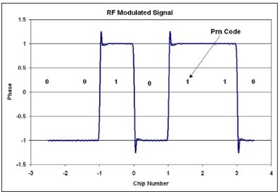
International Journal of Science and Research (IJSR)
ISSN (Online): 2319-7064
Index Copernicus Value (2013): 6.14 | Impact Factor (2013): 4.438
4. IRNSS-SPS Signal Generation
1) IRNSS System Overview
Indian Regional Navigation Satellite System (IRNSS) is an
independent, indigenously developed satellite navigation
system fully planned, established and controlled by the
Indian Space Research Organization (ISRO).
2) IRNSS Architecture
It majorly consists of:
Space segment
Ground segment.
User segment.
3) IRNSS Space Segment:
The minimum numbers of satellites that are required for the
The existing correlator technologies for SAT-NAV IRNSS constellation are seven. Three satellites in the
applications and their behavior are explained. Vision Geostationary Orbits (GSO) located at 32.5ºE, 83ºE and
correlator has resistance towards noisy and multipath 131.5ºE. Four in Inclined Geosynchronous orbits (IGSO)
environment it can be implemented and used for Signal with their longitude crossings 55ºE and 111.75ºE having two
Quality Monitoring of SAT NAV systems. Using these in each plane.
initial survey results and performance measures of Vision
Correlator we are proposing Vision Correlator Technology 4) IRNSS Ground Segment:
for SQM. Following figure6 shows the method of work. This segment is liable for maintenance and operation of
IRNSS constellation, which comprises of:
ISRO Navigation Centre
IRNSS Spacecraft Control Facility
IRNSS Range and Integrity Monitoring Stations
IRNSS Network Timing Centre
IRNSS CDMA Ranging Stations
Laser Ranging Stations
Figure 6: Block diagram of SQM system
Data Communication Network.
It consists of a satellite signal simulation unit (simulator)
User Segment: The User segment mainly consists of:
which is responsible for generating the satellite signals. The
Single frequency IRNSS receiver capable of receiving
necessary settings to get a signal, alike the real time ones are
SPS signal at L5 or S band frequency
customized in the simulator. The parameters that apply for
the satellites can be used. A dual frequency IRNSS receiver capable of receiving
both L5 and S band frequencies.
The simulated signal is then fed to the receiver. The A receiver compatible to IRNSS and other GNSS signals.
correlator inside the receiver gives the correlator a value
using which correlation plot is obtained. Figure7 show the interface between space and user
segments. IRNSS satellite provides standard positioning
An SQM system in turn consists of a computer which is in services (SPS) in L5 and S frequency bands.
full duplex communication with the receiver, gives the
visual of the correlation peak.
An algorithm or program to monitor the receiver (correlator)
is been developed from this system. Any deviation or spike
in the correlation curve can be visualized in the SQM
system.
Based on the correlation curve this data is further provided Figure 7: IRNSS Space and User Space Segment Interface
to the airborne users for navigation. If there are any
deviation in correlation curve such signals will be mitigated. 5) IRNSS Frequency Bands
For error detection and correction we generate an IRNSS- The IRNSS SPS service is transmitted on two frequency
SPS code by using INTERFACE CONTROLLER bands, L5 (1164.45 – 1188.45 MHz) and S (2483.5-2500
DOCUMENT (ICD). Using this code we generate a MHz). The carrier frequency of IRNSS SPS-L5 is 1176.45
correlation curve which stands as a reference for SQM. The MHz and bandwidth is 24MHz (1164.45-1188.45 MHz).
IRNSS architecture and frame structure is discussed in the The carrier frequency of IRNSS SPS-S is2492.028MHz and
following section. bandwidth 16.5MHz (2483.50-2500 MHz).
Volume 4 Issue 5, May 2015
www.ijsr.net
Paper ID: SUB154348 1232
Licensed Under Creative Commons Attribution CC BY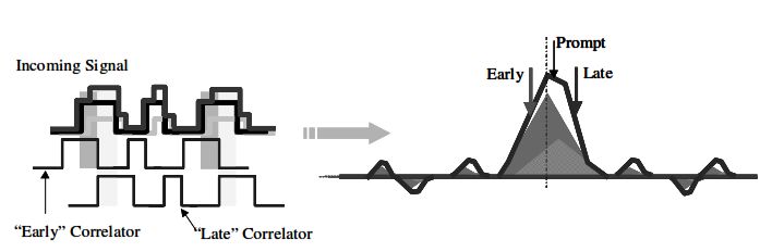
International Journal of Science and Research (IJSR)
                                               ISSN (Online): 2319-7064
                             Index Copernicus Value (2013): 6.14 | Impact Factor (2013): 4.438
6) IRNSS Frame Structure                                           satellite location which can be used to generate signals that
IRNSS Signal in Space transmits Navigation message                 are similar to the real time signals using a simulator. Using
through SPS service, in L5 and S frequency bands. The              this signal generated from the simulator we can obtain
IRNSS main frame is of 2400 symbols long which                     correlator values which can be used to generate test patterns
comprises of four sub frames. Each sub frame is 600                which help for improved SQM.
symbols transmitted at 50 symbols per second (sps). Each
sub frame has 16 bit synchronization word followed by 584          References
bits of interleaved data. Figure8 shows the IRNSS frame
structure.                                                         [1] “Multicorrelator Techniques For Robust Mitigation
                                                                       Of Threats To Gps Signal Quality”: Phd Thesis By
                                                                       Robert Eric Pheltes, The Dept Of Mechanical
                                                                       Engineering And The Committe Of Graduate Studies,
                                                                       Stanford University, Calofornia.
                                                                   [2] ”Practical     Signal     Quality    Monitoring For
                                                                       Augmentation Systems”: R. Eric Pheltes, Todd Walter,
                                                                       Dept Of Aeronautics And Astronautics, Stanford
                                                                       University, Stanford, California.
                                                                   [3] ”The Theory And Performance Of Novatel Inc’s
              Figure 8: IRNSS Frame Structure                          Vision Correlator”: Patric C Fenton And Jason Jones,
                                                                       Novatel Inc, California.
The sub frames 1 and 2 transmit primary navigation                 [4] ”Practical Sqm For Augmentation Systems”: R. Eric
parameters which are fixed. The sub frames 3 and 4 transmit            Pheltes, Todd Walter, Dept Of Aeronautics And
the secondary navigation parameters as messages.                       Astronautics, Stanford University, California.
                                                                   [5] ”Robust Signal Quality Monitoring And Detection Of
All the sub frames transmit the Telemetry word (TLM),                  Evil Waveform”: R.Eric Pheltes, Dennis M Akos, Per
Time of Week Count (TOWC), Alert, AutoNav, Subframe                    Enge, Dept Of Aeronautics And Astronautics, Stanford
ID, Spare Bit, Navigation data, Cyclic Redundancy Check                University, California.
(CRC) bits, and Tail bits. Subframe 3 and 4 in addition
transmit Message ID and PRN ID.

All these information that are available from the ICD and be
used to generate a signal from the simulator by configuring
it using same parameters. The data that is obtained by the
simulator will be same as that of a real time signal. Any
changes with respect to the signal parameters can be made
and test patterns can be generated which can be compared
with the real time satellite data. This customized signal
patterns and data can be made use for efficient SQM.

5. Conclusion
The Vision correlator characteristics have been discussed
with its performance results. The effect of multipath
interference on the vision correlator is lesser than the subtle
variations that occur in the standard correlator. Vision
Correlation process provides a significant improvement over
older multipath mitigating techniques. Vision Correlator can
remove the effects of multipath signal on the code and
carrier measurements when the delay of multipath signal is
less than 10meters of “Line of sight “of the signal and
mitigate their effects to fraction of meter. It also provides a
very useful static that can be used for Signal Quality
Monitoring of the received signal. This static can be used to
filter     the       data       that      is       unrepairable.
The advanced Vision Correlator hardware filters the noise
by super imposing successive chip transitions during a
specific time interval to form an average chip transition
(shape).Vision Correlator can detect Evil Waveforms caused
by unbalanced duty cycle, RF transition ringing and a
combination of the two.

Also the ICD helps by providing various satellite parameters
such as Satellite ID, PRN code, frequency bands and
                                               Volume 4 Issue 5, May 2015
                                                     www.ijsr.net
      Paper ID: SUB154348                                                                                          1233
                                     Licensed Under Creative Commons Attribution CC BY
You can also read