A Comparative Study on Additive and Subtractive Manufacturing
←
→
Page content transcription
If your browser does not render page correctly, please read the page content below
2018 ASEE Southeastern Section Conference

           A Comparative Study on Additive and Subtractive Manufacturing
                                         R. Radharamanan
                       School of Engineering, Mercer University, Macon, GA 31207

Abstract

The objective of this study is to effectively use Additive Manufacturing (AM) techniques (3D
printing) and Subtractive Manufacturing (SM) techniques (CNC machining) and compare and
contrast the process parameters and quality of parts produced. In particular, produce the exact
same part on two different machines: MakerBot Replicator 2X (AM), and Roland 3D CNC
Milling Machine (SM). The study provides details on the methodology of each manufacturing
process, the actual processes used, the parts produced, and the measurements made on each
produced part. The AM and SM were evaluated for the setup process of each method (number of
steps and setup time), ease of use, printing/ machining speed, accuracy, surface finish, and
percentage of material waste. Results obtained from students’ hands-on projects were presented
and discussed. Some of the difficulties encountered and the learning experience from the student
team are also presented and discussed.

Keywords

Additive manufacturing, CNC, 3D printing, rapid prototyping, and process parameters.

Introduction

Additive Manufacturing refers to a process by which digital 3D design data is used to build up a
component in layers by depositing material. The term "3D printing" is increasingly used as a
synonym for Additive Manufacturing. The term Additive Manufacturing holds within such
technologies like Rapid Prototyping (RP), Direct Digital Manufacturing (DDM), Layered
Manufacturing, and 3D Printing. There are different 3D printing methods that were developed to
build 3D structures and objects. The 3D printing technologies include: Stereolithography (SLA),
Digital Light Processing (DLP), Fused Deposition Modeling (FDM), Selective Laser Sintering
(SLS), Selective Laser Melting (SLM), Electronic Beam Melting (EBM), and Laminated Object
Manufacturing (LOM)1, 2.

Subtractive manufacturing is a process by which 3D objects are constructed by successively
cutting material away from a solid block of material. Subtractive manufacturing can be done by
manually cutting the material but is most typically done with a CNC Machine. Advanced CNC
machines utilize multiple tools and cut around at least three (x, y, and z) axes such that they
minimize the requirement for designers to flip the block. One of the principal advantages to
subtractive manufacturing is the ability to machine an extremely thin piece of plastic into a living
hinge. This kind of process is simply not yet possible in a 3D printer. For those prototypes that
require living hinge components it is useful to produce certain parts using additive
manufacturing while using the CNC machine for specialty components like a living hinge1, 2.

                         © American Society for Engineering Education, 2018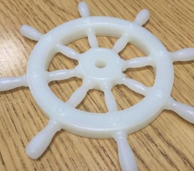
2018 ASEE Southeastern Section Conference

The objective of this study is to effectively use additive (3D Printing) and subtractive (CNC
machining) manufacturing process machines and compare and contrast the processes and parts
produced. In particular, compare AM and SM technologies using low cost process machines
available at Mercer University School of Engineering by producing the exact same part on two
different machines: the MakerBot Replicator 2X 3D Printer (AM), and the Roland 3D CNC
Milling Machine (SM). The methodology of each manufacturing process, the actual processes
used, the part produced, and the measurements of each produced part are presented and
discussed. The results of the measurements were compared for each process machine to
determine which provided the most accurate and precise machining for a typical lab project.
Other students' hands-on projects results were also presented and discussed.

Background Research

The Additive Manufacturing/Rapid Prototyping process allows the fast creation of products’
prototypes eliminating considerable amounts of resources and time spent on the project when
compared to traditional development design methods1. In Additive Manufacturing (AM), a
model initially generated using a three-dimensional Computer Aided Design (3D CAD) system,
can be fabricated directly without the need for process planning. Although this is not in reality as
simple as it first sounds, AM technology certainly significantly simplifies the process of
producing complex 3D objects directly from CAD data. This technology came about as a result
of developments in a variety of different technology sectors2.

The 3D printer is a machine allowing the creation of physical object from a three-dimensional
digital model, typically by laying down many thin layers of a material in succession3-5. This is
the main characteristic that distinguishes the 3D printers from other numerically controlled
(CNC) machines where the production process is subtractive, meaning that the final object is
achieved by removing the raw material using different mechanical tools2, 6.

The 3D printer has become a good alley of Rapid Prototyping, because the process of this
technology is easy to design, rapid to create, or replace7, 8. Manufacturers and product developers
used to find prototyping a complex, tedious, and expensive process that often impeded the
developmental and creative phases during the introduction of a new product and with this new
term and the 3D printer, all this process has become easy to manage and fast to accomplish8.
Laser-based rapid prototyping and other related technologies are also available for making 3D
parts9. The 3D printers have been used to build and test products and prototypes in laboratory
environments10, 11.

Methodology

For the purpose of this study, a simple 3D model was designed using SolidWorks12. A simple
model is used so that production is simple and measurements are easy to gather. The part is
designed specifically with the idea of comparison in mind. The descriptions of the machines,
software, and tools used for making the part are presented in the following sections.

                         © American Society for Engineering Education, 2018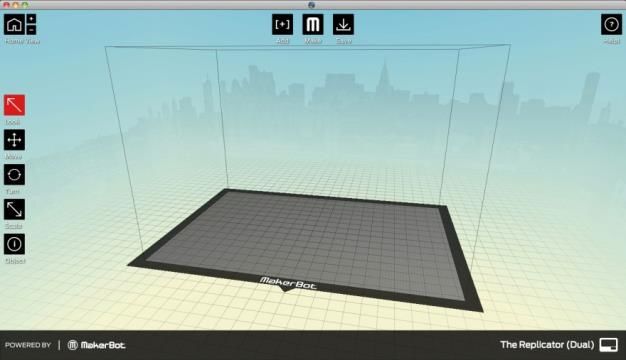
2018 ASEE Southeastern Section Conference

Design and Modeling

SolidWorks12

SolidWorks is solid modeling computer-aided design (CAD) software produced by Dassault
Systèmes SolidWorks Corp. The primary use of SolidWorks is for the production of 3D models
and conversion to STereoLithography (STL) file format for use on the manufacturing machines.

STL File

STL files are derived from word STereoLithography which was the first commercial additive
manufacturing (AM) process. STL files come in two formats: ASCII (text) and binary. ASCII
format is less common and is primarily used for teaching or illustration. STL files consist of list
of triangular facet with each triangular facet uniquely identified by three vertices or corners and a
unit normal vector. An STL file will hold no dimensions and it is the user’s responsibility to
know what unit of measurement is being used (in this case, inches).

Manufacturing Process

MakerBot Replicator 2X13

The MakerBot Replicator 2X (Figure 1), manufactured by MakerBot, is a full featured desktop
3D printer with experimental dual extrusion13. The dual extrusion allows for two interlaced
colors that print through aligned nozzles while not having to stop or pause during a print. The
printer has a flat, heated aluminum build plate that allows for higher variance in the heating and
cooling of the print surface. The printer features a six-sided, draft-blocking enclosure that
prevents uneven cooling, shrinkage, or warping. The printer uses fused deposition modeling
(FDM) to print and build parts.

Figure 1: MakerBot Replicator 2X                    Figure 2: MakerWare Launch Screen
The MakerBot Replicator comes with MakerBot MakerWare (Figure 2), software provided by
MakerBot. This is a free, easy-to-use, interface that allows one to move, rotate, scale, 3D models.
The primary file type used is STL files and MakerWare takes these files and uses an algorithm to
prepare the model for printing. The software allows for the use of “rafts”, or stabilizing printed
bases, that help ensure adhesion to the build plate and provide a better print quality and
“supports”, which are basic support materials that allow for printing of more complex models.

                          © American Society for Engineering Education, 2018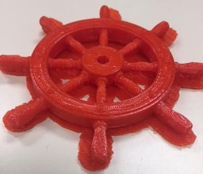
2018 ASEE Southeastern Section Conference
MakerBot also has a supplemental website, MakerBot Thingiverse14, which provides user made
models that can be quickly downloaded and printed using their software.
Roland 3D CNC Milling Machine MDX-40A15
The Roland 3D CNC Milling Machine (Figure 3 (a)) is a bench top CNC machine designed for
rapid prototyping. This particular machine is a 4-axis machine that can handle a variety of
materials, is G-code compatible, provides a smooth finish, and is relatively cheap15.
(a) (b)
Figure 3: (a) Roland 3D CNC Milling Machine MDX-40A; (b) Digital Caliper
For the majority of measurements, a digital caliper (Figure 3 (b)) was used. Digital calipers give
a highly accurate and precise measurement of distance on small objects. These calipers allow for
“zeroing” at any point along the slide, allowing for differential measurements.
Results and Discussions
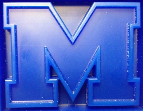
It was decided to design a part with simple and easy to measure features. The logic behind this is
that it is easier to measure a simple part and compare those specific measurements rather than a
highly complex part (contours perhaps). The part that was designed is the “Mercer University
M”, as seen in Figure 4 (a). The part has varying thicknesses and lengths that will allow for easy
comparisons. A dimensioned version of the file is seen in Figure 4 (b).
(a) (b)
Figure 4: Mercer University M
© American Society for Engineering Education, 2018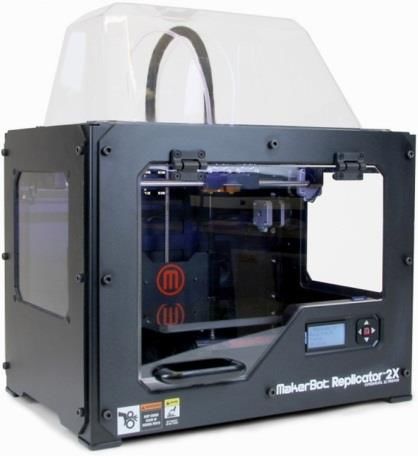
2018 ASEE Southeastern Section Conference

The part printed using MakerBot is shown in Figure 5. It has well defined features and finish.
The CNC milling machine entails a much different process than the 3D printer. While the same
files were used to make the part, the CNC machine requires supervision of the process. This is
due to the removal of material during the process. A wax block was chosen to make the part.
From previous studies2 it is known that CNC machines did offer an advantage: a far superior
finish than the 3D printer. The results indicate that it is true even with low cost CNC machine
and 3D printer used in this study. As it is seen in Figure 6, the CNC did have problems with the
small, inner crevice of the M. This was due to that specific dimension being so small and the tool
size used. It is possible to change to a smaller drill-bit; however this adds difficulty to the process
and increases machining time.

          Figure 5: MakerBot "M"                              Figure 6: CNC Milling Machine "M"

After the parts were manufactured, several measurements were taken and compared with the
original model. It should be noted that due to size restrictions the models were scaled and the
scale factor was used to make the comparisons based on original model dimensions. Several
lengths were compared to each other to check for accuracy and precision and a summarized
version of these can be seen in Table 1. Each dimension of the part made on the CNC machine
came out slightly larger which is to be expected and preferable as a post process finish can
remove excess material. The MakerBot produced part dimensions are slightly smaller due to
shrinkage of plastic material after printing and cooling.
                                    Table 1: Measurement Comparisons
 Machine      Scale     L1       % Error    H1      % Error    T2      % Error       T3   % Error   Average
                                                                                                    % Error
 SolidWorks
               ---     6.7300       ---    5.1600     ---     0.7900     ---     0.5500     ---       ---
 Model
 MakerBot     1:2.25   6.6758     -0.81%   5.1030    -1.1%    0.7845    -0.7%    0.5370   -2.36%     1.24%
 CNC
              1:2.25   6.7489     0.28%    5.1615    0.03%    0.7925    0.32%    0.5630    2.36%     0.75%
 Machine

After this comparison was done, a simple ranking system was made to give a numerical ranking
of each process machine for comparison. 15 participants (14 students and a faculty) were
involved in obtaining the ranking system using the Likert scale for quality with three-point
scales16. AM and SM process machines can be compared using the following process
characteristics 2. The ranking criteria for comparison are:

                                © American Society for Engineering Education, 2018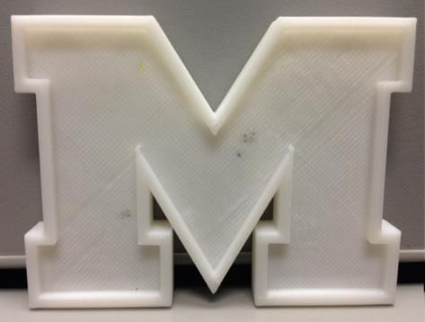
2018 ASEE Southeastern Section Conference
Setup – number of steps and setup time for each machine
Ease of use – how easy is it to use the machine
Machining speed – how quickly can the part be manufactured
Material waste (%) – percentage of material wasted due to machining/printing
Accuracy of measurements – how accurate the part is compared to the model
Surface finish – smoothness of the part surface
As seen in Table 2, using scale 1-3 (1 = poor; 2 = good; 3 = excellent), the MakerBot performed
better than the CNC Machine with respect to setup (number of steps and setup time), ease of use,
machining/printing speed, and material waste (%); the CNC machine is better than MakerBot
with respect to surface finish only. Overall, MakerBot performed better than CNC Machine.
Table 2: Machine Rankings
Ranking System
Machine Setup Software
Machining/ Material Surface
Machine No. of Time Ease of Accuracy Average
Printing Speed Waste (%) Finish
Steps (min) Use
MakerBot
8 7 3 2 2 2 2 2.167
Replicator 2X
Roland 3D
17 17 2 1 1 2 3 1.667
CNC Milling
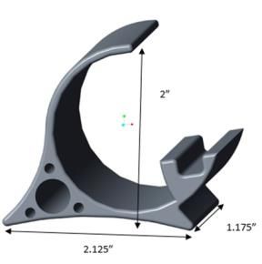
Similar results were obtained from other students' projects: captain's wheel and phone stand. The
CAD design and the parts made using MakerBot Replicator 2X and Roland CNC Mill are shown
in Figure 7. The measurements and results obtained from these parts made using the AM and SM
process machines were compared and found to be consistent. Further studies are needed to
validate the results using statistical methods.
Captain’s Wheel
(a) (b) (c)
Phone Stand
(a) (b) (c)
Figure 7: (a) CAD Design; (b) MakerBot 3D Print; and (c) Roland Mill CNC Part
© American Society for Engineering Education, 2018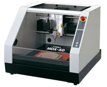
2018 ASEE Southeastern Section Conference

Conclusions and Recommendations

While the two machines representing AM and SM processes (MakerBot Replicator and Roland
CNC Mill) can rapidly produce parts and are easy to use, they are not necessarily equal. They are
both accurate enough for prototyping but also easy enough to use for a learning environment.
Both processes have their advantages and disadvantages. It is hard to make a case for one type
over the other as a broad recommendation. The recommendation really depends upon the
application and the desired result. If the desired result is for a faster product and the ability to
produce multiple parts simultaneously then the AM would be the most advantageous route.
However, if the surface finish is the primary concern while minimizing the amount of post
processing then the SM would be the desired route. The most appropriate solution would be a
combination of the two methods. The AM should be used to create the part while the capabilities
of the SM can be used to finish the product to provide a smoother surface. The overall
recommendation is to use a combination of both methods for the highest quality part straight out
of the machine. Through this study, the student teams were able to learn and understand two
different processes (AM and SM), advantages and disadvantages of each one of them, and when
to use them. The teams needed additional time to learn and use the CNC machine compared to
that of 3D printer. It is recommended that further studies are needed using other types of AM and
SM process machines to compare and validate the results of this study using statistical methods.

References
1.     Fedorov, A., Rapid Prototyping versus Traditional Development | Fresh Tilled Soil, April 4, 2009,
       Retrieved July 21, 2017.
2      Gibson, I., D. W. Rosen, and B. Stucker, Additive Manufacturing Technologies: 3D Printing, Rapid
       Prototyping, and Direct Digital Manufacturing, Second Edition, Springer, 2015.
3      Evans, B., Practical 3D Printers: The Science and Art of 3D Printing, A Press, 2012.
4      3D Printing Basics: The Free Beginner's Guide - 3D Printing Industry (2014, May). 3dPrinting
       Industry.com/3d-printing-basics-free-begineers- guide/, May 2014. Retrieved July 20, 2017.
5      Petronzio, M., How 3D Printing Actually Works, Mashable, March 28, 2013, meshable.com/
       2013/03/28/3d-printingexplained/, Retrieved July 14, 2017.
6      Gebhardt, A., Understanding Additive Manufacturing: Rapid Prototyping, Rapid Tooling, Rapid
       Manufacturing, Hanser Publishers, 2012.
7      Chua, C. K., K. F. Leong, and C. S. Lim, Rapid Prototyping: Principles and Applications, World Scientific,
       Third Edition, 2010.
8      Bryden, D., CAD and Rapid Prototyping for Product Design, Laurence King Publishing, 2014
9      Venuvinod, P. K. and W. Ma, Rapid Prototyping: Laser-Based and Other Technologies, Springer, 2004.
10     Radharamanan, R., A. C. M. Rosa, B. D. Neto, and V. F. B. Santos, "Use of 3D Printers to Design, Build,
       Test, and Fly a Quadcopter Drone," The Journal of Management and Engineering Integration, Vol. 9,
       No. 1, Summer 2016, pp.24-33.
11     Radharamanan, R., A. P. Vilanova, J. P. M. Moreira, and W. de Lima, "Additive Manufacturing for the
       Production of a Knee Prototype," The Journal of Management and Engineering Integration, Vol. 10, No. 1,
       Summer 2017, pp.1-13.
12     3D CAD Design Software SolidWorks. (n.d.), http://www.solidworks.com/, Retrieved July 20, 2017,
13     "MakerBot Replicator 2X User Manual", www.makerbot.com/Replicator2X, Retrieved July 17, 2017.
14     Thingiverse - Digital Designs for Physical Objects. (n.d.), http://www.thingiverse.com/, Retrieved July 14,
       2017.

                            © American Society for Engineering Education, 2018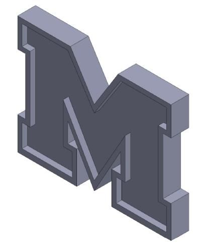
2018 ASEE Southeastern Section Conference

15     Large Format Printer | Large Format Printers | Roland DGA. (n.d.), http://www.rolanddga.com/,
       Retrieved July 14, 2017.
16     Likert Scale Examples of Survey - Iowa State University Extension, https://www.extension.iastate.edu/
       Documents/.../LikertScaleExamplesforSurveys.pdf Retrieved January, 20, 2018.

R. Radharamanan

Dr. R. Radharamanan is currently working as Professor of Industrial Engineering at Mercer
University in Macon, Georgia. He has forty four years of teaching, research, and consulting
experiences. His primary research and teaching interests are in the areas of manufacturing
systems, rapid prototyping, robotics and automation, innovation and entrepreneurship, quality
engineering, and product and process development. He has organized and chaired/co-chaired
seven international conferences and three regional conferences. He has received two teaching
awards, several research and service awards in the United States and in Brazil. His present and
past professional affiliations include ASEE, IIE, ASQ, SME, ASME, and ISPE.

                           © American Society for Engineering Education, 2018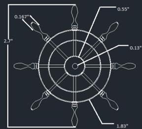
You can also read