Accurate Bracket Placement with an Indirect Bonding Method Using Digitally Designed Transfer Models Printed in Different Orientations-An In Vitro ...
←
→
Page content transcription
If your browser does not render page correctly, please read the page content below
Journal of
              Clinical Medicine

Article
Accurate Bracket Placement with an Indirect Bonding Method
Using Digitally Designed Transfer Models Printed in Different
Orientations—An In Vitro Study
Julia Süpple           , Julius von Glasenapp, Eva Hofmann                 , Paul-Georg Jost-Brinkmann             and Petra Julia Koch *

                                          Department of Orthodontics, Dentofacial Orthopedics and Pedodontics, Charité Center for Oral Health Sciences
                                          CC3, Charité-Universitätsmedizin Berlin, Corporate Member of Freie Universität Berlin and
                                          Humboldt-Universität zu Berlin, Aßmannshauser Straße 4-6, 14197 Berlin, Germany;
                                          julia.suepple@charite.de (J.S.); julius.von-glasenapp@charite.de (J.v.G.); eva.hofmann@charite.de (E.H.);
                                          paul-g.jost-brinkmann@charite.de (P.-G.J.-B.)
                                          * Correspondence: petra-julia.koch@charite.de

                                          Abstract: Objective: A digital workflow opens up new possibilities for the indirect bonding (IDB)
                                          of brackets. We tested if the printing orientation for bracket transfer models on the build platform
                                          of a 3D printer influences the accuracy of the following IDB method. We also evaluated the clinical
                                          acceptability of the IDB method combining digitally planned and printed transfer models with
                                          the conventional fabrication of pressure-molded transfer trays. Materials and Methods: In total,
                                          27 digitally planned bracket transfer models were printed with both 15◦ and 75◦ angulation from
                                horizontal plane on the build platform of a digital light processing (DLP) printer. Brackets were

                                          temporarily bonded to the transfer models and pressure-molded trays were produced on them.
Citation: Süpple, J.; von Glasenapp,
                                          IDB was then performed using the trays on the respective plaster models. The plaster models
J.; Hofmann, E.; Jost-Brinkmann,
                                          were scanned with an optical scanner. Digitally planned pre-bonding and scanned post-bonding
P.-G.; Koch, P.J. Accurate Bracket
                                          bracket positions were superimposed with a software and resulted in three linear and three angular
Placement with an Indirect Bonding
Method Using Digitally Designed
                                          deviations per bracket. Results: No statistically significant differences of the transfer accuracy of
Transfer Models Printed in Different      printed transfer models angulated 15◦ or 75◦ on the 3D printer build platform were found. About
Orientations—An In Vitro Study. J.        97% of the linear and 82% of the angular deviations were within the clinically acceptable range
Clin. Med. 2021, 10, 2002. https://       of ±0.2 mm and ±1◦ , respectively. The highest inaccuracies in the linear dimension occurred in
doi.org/10.3390/jcm10092002               the vertical towards the gingival direction and in the angular dimension in palatal crown torque.
                                          Conclusion: For the IDB method used, the printing orientation on the build platform did not have a
Academic Editors: Falk Schwendicke        significant impact on the transfer accuracy.
and Gianrico Spagnuolo

                                          Keywords: indirect bonding; transfer accuracy; transfer tray; transfer model; printing orientation;
Received: 20 March 2021
                                          CAD/CAM; digital light processing; 3D printing
Accepted: 4 May 2021
Published: 7 May 2021

Publisher’s Note: MDPI stays neutral
                                          1. Introduction
with regard to jurisdictional claims in
published maps and institutional affil-         In the beginning of the 1970s L. F. Andrews introduced the straight-wire appliance and,
iations.                                  ever since, accurate bracket placement has been an important objective for orthodontists.
                                          Tooth movement was no longer achieved by time-consuming wire-bending, but integrated
                                          into the bracket design with a predetermined slot angulation. Accurate bracket positioning
                                          of the straight-wire appliance is supposed to result in a correct slot angulation causing the
Copyright: © 2021 by the authors.
                                          intended tooth movement and treatment outcome [1,2].
Licensee MDPI, Basel, Switzerland.
                                                Direct bonding is the most frequently used method to attach a straight-wire appliance
This article is an open access article
                                          to the patients’ teeth. Every bracket is bonded separately [3]. To accelerate and facilitate this
distributed under the terms and           process and to increase the comfort for patient and orthodontist, Silverman et al. developed
conditions of the Creative Commons        indirect bonding (IDB) in 1972. A laboratory-made transfer tray containing the brackets
Attribution (CC BY) license (https://     allowed to simultaneously bond them to a group of teeth.
creativecommons.org/licenses/by/                In the conventional IDB workflow, a dental impression is taken to create a dental cast.
4.0/).                                    Brackets are temporarily attached to the model and a transfer tray is produced on top of

J. Clin. Med. 2021, 10, 2002. https://doi.org/10.3390/jcm10092002                                               https://www.mdpi.com/journal/jcm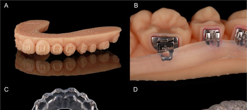
J. Clin. Med. 2021, 10, 2002                                                                                                              2 of 13

                                          it [4]. Many different designs and materials for conventional IDB trays have been tested
                                          since and show clinical applicability. Most commonly used in the conventional workflow
                                          are polyvinyl siloxane and single- or double-vacuum-formed trays, as well as combinations
                                          of both [5–8]. However, these procedures require extra time for taking the impression and
                                          extra laboratory steps for producing the tray, which increases the expenses [9]. Thus, only
                                          about 12% of the clinicians are using it so far [10].
                                                In recent years, CAD/CAM allowed a digital workflow for IDB. Intraoral scanners
                                          provide 3D data of the dental arches that can be imported into software programs. An
                                          orthodontic treatment can then be planned virtually, including the precise digital placement
                                          of brackets [11]. Based on these data, transfer models or trays can be 3D printed with
                                          various printer types for indirect bonding.
                                                The 3D printing of IDB trays was investigated in only a few in vitro studies. The
                                          testing of different materials and designs endorses their clinical usability [12–16].
                                                However, the printing of dental models was the objective of various investigations.
                                          Especially the digital light processing (DLP) printers, as used in our study, show high
                                          precision in printing dental models and are commonly used in orthodontics [17,18].
                                                A frequently mentioned problem in 3D printing that might affect the accuracy is
                                          the printing orientation on the build platform. To place as many models as possible,
                                          they are often arranged vertically. The staircase effect that is caused by printing in layers
                                          appears different depending on the orientation on the platform and affects the surface
                                          quality [19]. More knowledge is needed about the impact of this printing parameter on the
                                          accuracy. There is limited information available about the testing of different orientations
                                          and not for all printer types, materials, and object geometries. This has led to inconsistent
                                          recommendations [19–21].
                                                For our study, we 3D printed transfer models with frames for every bracket position to
                                          produce IDB trays. Our aim was to test different printing orientations on the build platform
                                          in two groups. We asked whether the printing orientation influences the accuracy and if
      J. Clin. Med. 2021, 10, x FOR PEER REVIEW                                                                      3 of 14
                                          the IDB method used—combining both the conventional and digital workflow—transfers
                                          the brackets with clinically acceptable accuracy (Figure 1).

                                  Figure 1.1.Flow
                                  Figure      Flowchart of the
                                                    chart   of IDB
                                                               the workflow and analysis
                                                                   IDB workflow          of transferof
                                                                                   and analysis      accuracy with
                                                                                                       transfer    bracket position
                                                                                                                accuracy    with bracket position
                                  deviations.
                                  deviations.
                                  2. Materials and Methods
                                       Plaster models of 27 patients with permanent dentition and in need of orthodontic
                                  treatment were digitized with an optical scanner (TRIOS®3W, 3Shape, Copenhagen,
                                  Denmark). The scans were saved as standard tessellation language (STL) files and
                                  imported to the treatment simulation software OnyxCeph3™ (Image Instruments,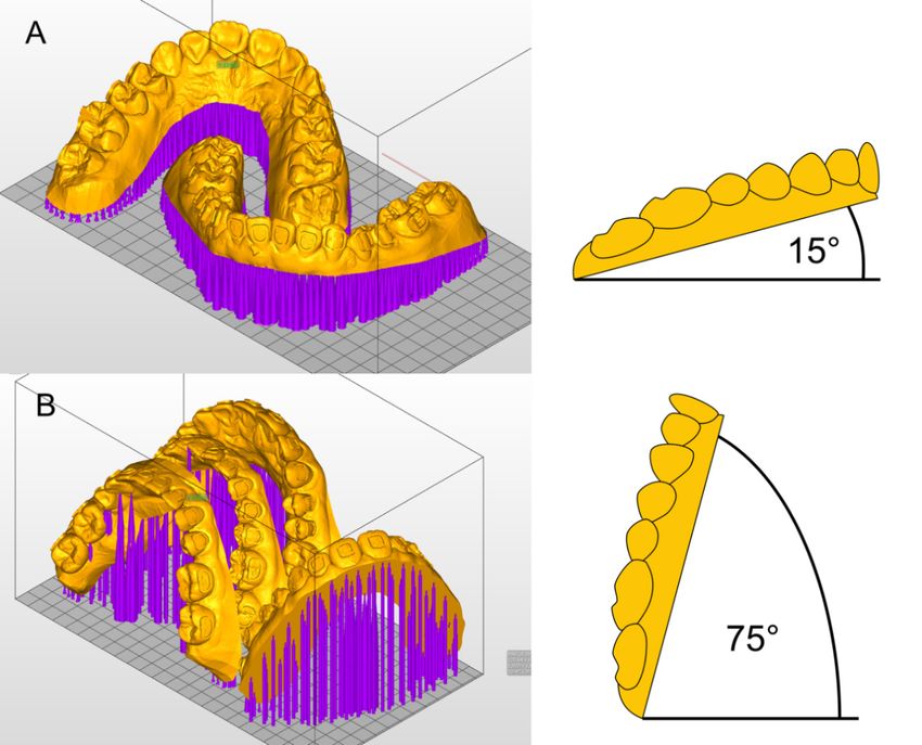
J. Clin. Med. 2021, 10, 2002                                                                                          3 of 13

                                 2. Materials and Methods
                                         Plaster models of 27 patients with permanent dentition and in need of orthodontic
                                    treatment were digitized with an optical scanner (TRIOS® 3W, 3Shape, Copenhagen, Den-
                                    mark). The scans were saved as standard tessellation language (STL) files and imported
                                    to the treatment simulation software OnyxCeph3 ™ (Image Instruments, Chemnitz, Ger-
                                    many). All bracket positions were determined and virtually placed using the OnyxCeph3 ™
                                    FA-Bonding module. The patient models were planned with metal brackets (0.018-inch
                                    slots) for incisors, canines and premolars (discovery® smart, Dentaurum, Ispringen, Ger-
                                    many) and metal tubes for the first and second molars (Ortho-Cast M-Series, Dentaurum,
                                    Ispringen, Germany) in the upper and lower jaw. Eight patient models got ceramic brackets
                                    (discovery® pearl, Dentaurum, Ispringen, Germany) from the second premolar on one
                                    side to the second premolar on the contralateral side in the upper jaw. The pre-bonding
                                    bracket positions were set for every tooth including the first and second molars. Based on
                                    the determined bracket positions, frames were virtually created around every bracket in
                                    the OnyxCeph3 ™ Kylix 3D module (Image Instruments, Chemnitz, Germany). All transfer
J. Clin. Med. 2021, 10, x FOR PEER REVIEW                                                                                         4 of 1
                                    models including the bracket frames were exported as STL files. The parameters used for
                                    the dimension of the frames are shown in Figure 2.

                                  Figure2.2.Parameters
                                 Figure      Parameters  used
                                                       used    in the
                                                            in the    OnyxCeph
                                                                   OnyxCeph
                                                                               3 ™ Kylix
                                                                            3 ™ Kylix    3D module
                                                                                      3D module     (Image
                                                                                                (Image       Instruments,
                                                                                                       Instruments,       Chemnitz,
                                                                                                                    Chemnitz,
                                  Germany).
                                 Germany).

                                 2.1. Printing the Bracket Transfer Models
                                      The STL files of the transfer models were imported to the Asiga MAX™ printe
                                 software (Asiga Composer, Scheu Dental, Iserlohn, Germany). All 27 patient models wer
J. Clin. Med. 2021, 10, 2002                                                                                                  4 of 13

J. Clin. Med. 2021, 10, x FOR PEER REVIEW                                                                                          5 of 14

                                 2.1. Printing the Bracket Transfer Models
                                      The STL
                                  solution        files of ®the
                                             (IMPRIMO           transferLiquid,
                                                             Cleaning     modelsScheu
                                                                                   were Dental,
                                                                                         imported    to the Asiga
                                                                                                  Iserlohn,  Germany)MAX™  for printer
                                                                                                                               10 min. The
                                 software   (Asiga   Composer,   Scheu  Dental,  Iserlohn,  Germany).   All 27
                                  models were then light‐cured for five minutes using a resin‐specific program  patient models   were
                                                                                                                                    with a
                                 sent to a 3D  printer  with  DLP  technology  (Asiga  MAX™,     Scheu  Dental,
                                  wavelength of 405 nm in a nitrogen environment (IMPRIMO Cure, Scheu Dental,    Iserlohn,
                                                                                                                 ®          Germany).
                                 They  were Germany).
                                  Iserlohn,   oriented horizontally
                                                            A finishedor transfer
                                                                         verticallymodel
                                                                                    on theisbuild
                                                                                             shownplatform  of the4A.
                                                                                                      in Figure    printer (Figure 3).

      Figure 3. Printing
      Figure 3. Printingorientation
                          orientationinin(A)
                                          (A)Group
                                              GroupHH and
                                                    and (B)(B) Group
                                                            Group     V Asiga
                                                                   V in in Asiga MAX™
                                                                              MAX™     printer
                                                                                    printer     software
                                                                                            software     (Asiga
                                                                                                     (Asiga     Composer,
                                                                                                            Composer, ScheuScheu
      Dental, Iserlohn)  and  model  angulations.
      Dental, Iserlohn) and model angulations.

                                  2.2. (A)
                                       Fabricating
                                           Group H:the
                                                     27Pressure‐Molded    15◦ from
                                                                        Transfer
                                                       models were tilted        Trays
                                                                                   the horizontal build platform and printed.
                                 One patient  model per
                                       All brackets       printtemporarily
                                                       were     (upper and lower  jaw)into
                                                                             bonded    was placed  on the build
                                                                                            their frames   withplatform   and
                                                                                                                 a water‐soluble
                                 printed in 30 to 45 min.
                                  adhesive (Ortho Laboratory Adhesive for Indirect        Bonding, 3M™ Unitek, St. Paul, MN,
                                      (B) Group V: another 27 models were tilted 15◦ from the vertical line (75◦ from the
                                  USA). The brackets were then blocked out up to the middle of the slots with a silicone
                                 horizontal build  platform), which allowed the placement of two sets of patient models on
                                  (SIL‐KITT®, Scheu Dental, Iserlohn, Germany). The hooks of the molar tubes were also
                                 the platform. One print took 75 to 90 min.
                                  covered (Figure 4B). The models were placed® into a pressure molding machine
                                      Light-curing methacrylate-based resin (IMPRIMO LC model, Scheu Dental, Iserlohn,
                                  (BIOSTAR
                                 Germany) was
                                             ®, Scheu Dental, Iserlohn, Germany) to produce an ethylene‐vinyl acetate tray
                                                  used for printing. A slice thickness of 0.05 mm was chosen. Support
                                  (BIOPLAST
                                 structures were 2.0
                                               ®
                                                  added× automatically
                                                          125 mm, Scheu,      Iserlohn,
                                                                         and without     Germany).
                                                                                     connection  to theThe  tray—containing
                                                                                                        frames. To attach the the
                                  brackets—was     cut  into shape  (Figure  4C) and  put  into water  for 30 min
                                 support structures securely to the build platform, a 0.3 mm thick base plate was  to created.
                                                                                                                      dissolve the
                                 After printing, the models were detached from the build platform and the support struc-from
                                  adhesive.  To  allow   an easy  removal  of the tray after IDB, it was  cut with  a scalpel
                                  the margin
                                 tures         to the middle
                                       were removed            of the brackets
                                                       with a scraper.         or tubes. by the printer producer, the models
                                                                       As recommended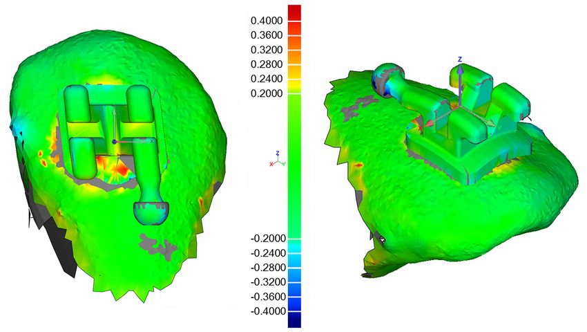
J. Clin. Med. 2021, 10, 2002                                                                                                   5 of 13

                                     were then immersed into an ultrasonic cleaning device (IMPRIMO® Clean, Scheu Den-
                                     tal, Iserlohn, Germany) filled with a butyldiglycol-based detergent solution (IMPRIMO®
                                     Cleaning Liquid, Scheu Dental, Iserlohn, Germany) for 10 min. The models were then
                                     light-cured for five minutes using a resin-specific program with a wavelength of 405 nm in
                                     a nitrogen environment (IMPRIMO® Cure, Scheu Dental, Iserlohn, Germany). A finished
J. Clin. Med. 2021, 10, x FOR PEER REVIEW                                                                                6 of 14
                                     transfer model is shown in Figure 4A.

      Figure 4. Fabricating the pressure‐molded transfer trays: (A) printed model with frames for brackets and tubes; (B) provi‐
      Figure 4. Fabricating the pressure-molded transfer trays: (A) printed model with frames for brackets and tubes; (B)
      sory bonded brackets and tubes with silicone for blocking‐out; (C) pressure‐molded transfer tray with embedded brackets
      provisory bonded brackets and tubes with silicone for blocking-out; (C) pressure-molded transfer tray with embedded
      and tubes; (D) tray removal with a scaler after bonding.
      brackets and tubes; (D) tray removal with a scaler after bonding.
                                 2.3. Bracket Bonding
                                 2.2. Fabricating the Pressure-Molded Transfer Trays
                                       Plaster models for every patient were cast using silicone forms of the initial patient
                                       All brackets were temporarily bonded into their frames with a water-soluble adhesive
                                 situation.
                                 (OrthoTheLaboratory
                                            facial toothAdhesive
                                                          surfaces for  Indirect
                                                                    of the plasterBonding,  3M™cleaned
                                                                                    models were    Unitek, with
                                                                                                            St. Paul,  MN, USA).
                                                                                                                 isopropanol    and
                                 The   brackets
                                 Transbond™      were
                                                 XT     then
                                                     Primer   blocked
                                                             (3M        out
                                                                   Unitek   up  to the middle
                                                                            Deutschland,  Neuss,of the slots
                                                                                                   Germany)  with
                                                                                                              was  a silicone
                                                                                                                   applied   on(SIL-
                                                                                                                                 the
                                 KITT® , Scheu
                                 expected        Dental,
                                            bracket       Iserlohn,
                                                     positions.  TheGermany).    Thewere
                                                                     bracket bases   hookscleaned
                                                                                            of the molar
                                                                                                    with atubes were
                                                                                                           cotton     also
                                                                                                                  pellet   covered
                                                                                                                         soaked   in
                                 (Figure  4B). The  models   were  placed  into a pressure molding   machine   (BIOSTAR   ® , Scheu
                                 acetone and Transbond™ XT (3M Unitek Deutschland, Neuss, Germany) was allocated                  to
                                 Dental, Iserlohn, Germany) to produce an ethylene-vinyl acetate tray (BIOPLAST® 2.0
                                 them. Afterwards, the tray was put on the model and material excess of the composite
                                 × 125 mm, Scheu, Iserlohn, Germany). The tray—containing the brackets—was cut into
                                 was removed with a dental probe. Every bracket was light‐cured with 3200 mW/cm2 in
                                 shape (Figure 4C) and put into water for 30 min to      dissolve the adhesive. To allow an easy
                                 the extra power light polymerization mode (Valo® Cordless, Ultradent Products, Cologne,
                                 removal of the tray after IDB, it was cut with a scalpel from the margin to the middle of the
                                 Germany) for 12 s while holding the tray in place with slight and even occlusal pressure.
                                 brackets or tubes.
                                 The tray was then removed with the help of a scaler (Figure 4D).
                                 2.3. Bracket Bonding
                                 2.4. Comparing Pre‐ and Post‐Bonding Bracket Position
                                       Plaster models for every patient were cast using silicone forms of the initial patient
                                       A scanning powder (METAL‐POWDER Dry blue, R‐dental Dentalerzeugnisse,
                                 situation.
                                 Hamburg,    Germany)
                                       The facial        was sprayed
                                                  tooth surfaces of theon the plaster
                                                                        plaster modelsmodels   to avoidwith
                                                                                         were cleaned   reflections from and
                                                                                                            isopropanol   the
                                 metal  surfaces. Every  model was   scanned  to digitize the post‐bonding  bracket
                                 Transbond™ XT Primer (3M Unitek Deutschland, Neuss, Germany) was applied on the    positions
                                 (TRIOS®3W, 3Shape, Copenhagen, Denmark). Both pre‐ and post‐bonding STL data were
                                 imported to Geomagic Control® (3D Systems Inc., Rock Hill, SC, USA). Every tooth was
                                 cut out and saved both in pre‐ and post‐bonding situation. In the image‐processing
                                 software, the corresponding teeth were superimposed with a local best‐fit alignment
                                 (Figure 5) and resulted in three linear and three angular measurements for each bracket.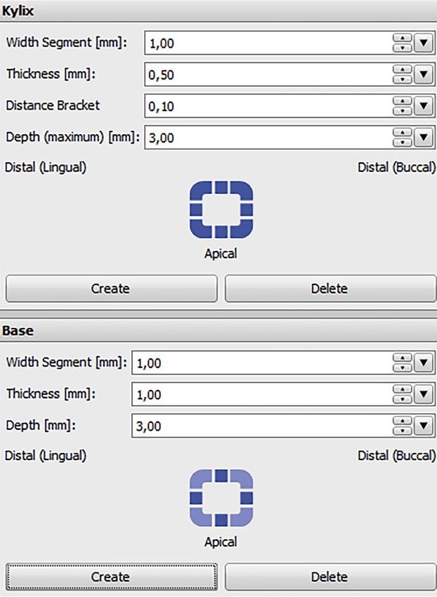
J. Clin. Med. 2021, 10, 2002 6 of 13
expected bracket positions. The bracket bases were cleaned with a cotton pellet soaked in
acetone and Transbond™ XT (3M Unitek Deutschland, Neuss, Germany) was allocated
to them. Afterwards, the tray was put on the model and material excess of the composite
was removed with a dental probe. Every bracket was light-cured with 3200 mW/cm2 in
the extra power light polymerization mode (Valo® Cordless, Ultradent Products, Cologne,
Germany) for 12 s while holding the tray in place with slight and even occlusal pressure.
The tray was then removed with the help of a scaler (Figure 4D).
2.4. Comparing Pre- and Post-Bonding Bracket Position
A scanning powder (METAL-POWDER Dry blue, R-dental Dentalerzeugnisse, Ham-
burg, Germany) was sprayed on the plaster models to avoid reflections from the metal sur-
faces. Every model was scanned to digitize the post-bonding bracket positions (TRIOS® 3W,
3Shape, Copenhagen, Denmark). Both pre- and post-bonding STL data were imported
to Geomagic Control® (3D Systems Inc., Rock Hill, SC, USA). Every tooth was cut out
and saved both in pre- and post-bonding situation. In the image-processing software, the
J. Clin. Med. 2021, 10, x FOR PEER REVIEW
corresponding teeth were superimposed with a local best-fit alignment (Figure 5) 7 of
and14
resulted in three linear and three angular measurements for each bracket.
Figure 5. Illustration of the output from the superimposition in Geomagic Control®
® software (3D Systems Inc., Rock Hill,
software (3D Systems Inc., Rock Hill,
SC, USA) for tooth 13 of a random patient.
SC, USA) for tooth 13 of a random patient.
2.5.
2.5. Statistical
Statistical Analysis
Analysis
All measurements
All measurements were were inserted
insertedinto
intothe
theSPSS
SPSS software
software (IBM
(IBM SPSSSPSS Statistics
Statistics 27,
27, Ar-
Armonk,
monk, NY,NY, USA).
USA). MeansMeans and standard
and standard deviations
deviations of the numbers
of the absolute absolute were
numbers were
calculated
calculated for the tooth groups (incisors/canines/premolars/molars)
for the tooth groups (incisors/canines/premolars/molars) in Groups H and V. in Groups H and V.
A linear mixed model was conducted two times: one using all linear
A linear mixed model was conducted two times: one using all linear dimensions dimensions
(mesiodistal/vertical/orovestibular)
(mesiodistal/vertical/orovestibular)asasdependent
dependentvariable
variableandand one
one using
using all angular
all angular
dimensions
dimensions (torque/rotation/tip).
(torque/rotation/tip).The
TheGroups
GroupsHHand andV,V,upper
upperandandlower
lower jaw,
jaw, as
as well as
well as
the tooth groups (incisor/canine/premolar/molar)
(incisor/canine/premolar/molar) were
weresetset
asas
factors.
factors.
Results
3. Results
We analyzed the transfer accuracy of 1453 brackets and tubes, 729 in Group H (15 (15°◦
◦
angulation) and 724 in Group V (75°
(75 angulation). Overall, 11 teeth of the 27 patient models
were missing due to agenesis or early tooth loss. In total, 15 brackets in Group H were lost
during the transfer procedure and 17 in Group V. One bracket position analysis in Group
H and four in Group V were considered invalid due to a failing superimposition in the
Geomagic software.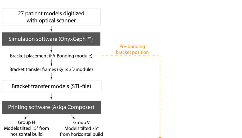
J. Clin. Med. 2021, 10, 2002                                                                                                                           7 of 13

                                        were missing due to agenesis or early tooth loss. In total, 15 brackets in Group H were lost
                                        during the transfer procedure and 17 in Group V. One bracket position analysis in Group
                                        H and four in Group V were considered invalid due to a failing superimposition in the
                                        Geomagic software.
                                              The linear mixed model shows no significant difference between Groups H and V in
                                        the linear or angular dimensions (Table 1).

                                     Table 1. Mixed model: Fixed effects for the linear and angular dimension.

                                                                                                                 p-Value
                                  Factors                                             Linear Dimension                        Angular Dimension
                        Groups (H/V)                                                           0.60                                     0.71
                Dimensions (linear/angular)                                                   0.00 *                                    0.24
      Tooth groups (incisors/canines/premolars/molars)                                        0.01 *                                   0.00 *
                     Jaws (upper/lower)                                                       0.00 *                                    0.06
                   Groups × dimensions a                                                       0.17                                     0.34
                   Groups × tooth groups a                                                     0.06                                    0.04 *
               Groups × upper and lower jaw a                                                  0.88                                     0.78
                Dimensions × tooth groups a                                                    0.27                                    0.00 *
             Dimensions × upper and lower jaw a                                                0.98                                     0.71
            Tooth groups × upper and lower jaw a                                               0.32                                     0.41
                                      * p < 0.05 indicates statistical significance. a interaction between the factors (×).

                                              However, deviations in the tooth groups (of both Group H and V) are significant for
                                         every dimension: In the linear dimension the molars show the worst and the canines the
                                         best results of transfer accuracy, while in the angular dimension it is the other way round.
                                              A significant difference between upper and lower jaw exists in the overall linear
                                         dimension, showing better transfer accuracy in the lower jaw.
                                              Table 2 presents the means and standard deviations of the transfer accuracy in all
                                         dimensions as calculated with absolute numbers. The best linear transfer accuracy is
                                         achieved in the orovestibular direction with a mean deviation of 0.03 mm in Group H and
                                         0.02 mm in Group V. The vertical dimension shows a mean deviation of 0.08 mm in Groups
                                         H and V and is, therefore, the most inaccurate. The overall deviations for each of the three
                                         linear directions are statistically significant (Table 1).

                Table 2. Differences between pre- and post-bonding positions in Group H and V for different tooth types.

                                                                                           Mean b ± SD
                                          Mesiodistal             Vertical           Orovestibular
 Tooth Type        Group        na                                                                          Torque (◦ )       Rotation (◦ )       Tip (◦ )
                                            (mm)                   (mm)                 (mm)
                      H         210         0.05 ± 0.04         0.07 ± 0.05            0.02 ± 0.02          0.49 ± 0.36       0.53 ± 0.47       0.77 ± 0.61
    Incisors
                      V         209         0.05 ± 0.04         0.07 ± 0.06            0.02 ± 0.02          0.50 ± 0.40       0.55 ± 0.46       0.79 ± 0.60
                      H         107         0.07 ± 0.06         0.07 ± 0.07            0.03 ± 0.05          0.64 ± 0.55       0.82 ± 0.80       0.72 ± 0.65
   Canines
                      V         106         0.06 ± 0.06         0.07 ± 0.07            0.03 ± 0.03          0.64 ± 0.53       0.72 ± 0.69       0.67 ± 0.54
                      H         207         0.07 ± 0.07         0.09 ± 0.07            0.02 ± 0.02          0.80 ± 0.59       0.67 ± 0.69       0.55 ± 0.48
  Premolars
                      V         206         0.06 ± 0.07         0.08 ± 0.06            0.02 ± 0.05          0.74 ± 0.58       0.59 ± 0.67       0.56 ± 0.54
                      H         205         0.06 ± 0.07         0.09 ± 0.06            0.03 ± 0.03          0.68 ± 0.49       0.56 ± 0.62       0.23 ± 0.26
    Molars
                      V         203         0.06 ± 0.07         0.10 ± 0.08            0.03 ± 0.03          0.79 ± 0.68       0.56 ± 0.64       0.26 ± 0.37
                      H         729         0.06 ± 0.06         0.08 ± 0.06            0.03 ± 0.03          0.65 ± 0.51       0.62 ± 0.64       0.55 ± 0.55
     Total
                      V         724         0.06 ± 0.06         0.08 ± 0.07            0.02 ± 0.04          0.67 ± 0.57       0.59 ± 0.61       0.56 ± 0.55
                       a   number of brackets used for analysis.   b   mean calculated with absolute numbers of transfer deviations.

                                             No significant difference was found for the angular dimensions (Table 1). A mean
                                         deviation of 0.55◦ in Group H and 0.56◦ in Group V reveals that tip is transferred most
                                         accurately. A mean of 0.65◦ in Group H and 0.67◦ in Group V identifies torque to be the
                                         most inaccurately transferred angular dimension (Table 2).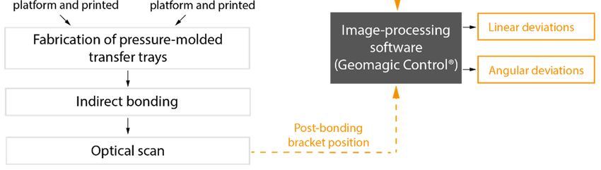
J. Clin. Med. 2021, 10, 2002                                                                                                            8 of 13

                                             We considered linear deviations of ±0.2 mm and angular deviations of ±1◦ clinically
                                        acceptable. The percentage of transfers outside of the acceptable range is presented in
                                        Table 3.

      Table 3. Prevalence of bracket transfers outside of the clinically acceptable range in Group H and V for different tooth types.

                               Mesiodistal (%)          Vertical (%)      Orovestibular (%)     Torque (%)     Rotation (%)       Tip (%)
  Tooth Type        Group      Mesial     Distal   Occlusal    Gingival   Oral   Vestibular    PCT     LCT      MR      DR     MCT      DCT
                      H         0.5        0.0       0.5          1.4     0.0        0.0        7.1     1.0      5.2     8.1    15.7    17.1
    Incisors
                      V         0.0        1.0       0.5          2.9     0.0        0.0        8.6     1.0      6.2     6.7    18.2    12.0
                      H         3.7        0.0       0.0          5.6     0.9        0.0       15.0     1.9      5.6    22.4    15.9     9.3
    Canines
                      V         2.8        0.0       0.9          3.8     0.0        0.0       17.0     2.8      6.6    14.2     7.5    15.1
                      H         2.9        1.0       1.0          3.9     0.0        0.0       31.4     2.9      3.4    15.0     6.8     5.8
   Premolars          V         1.9        0.5       0.5          4.4     0.5        0.0       22.8     2.4      8.3     7.8     9.7     4.9
                      H         4.9        1.5       0.0          4.9     0.5        0.0       20.5     1.5     11.2     4.4     0.5     1.5
     Molars           V         0.5        3.0       0.0          9.9     0.5        0.0       23.6     1.5     12.8     3.9     2.0     2.5
                      H         1.9        1.6       0.4          3.7     0.3        0.0       18.9     1.8      6.4    11.1     8.0     9.3
      Total           V         1.1        1.2       0.4          5.4     0.3        0.0       18.1     1.8      8.7     7.3     9.7     7.7
      PCT = Palatal crown torque, LCT = Labial crown torque, MR = Mesiorotation, DR = Distorotation, MCT = Mesial crown tip, DCT = Distal
      crown tip.

                                              The greatest deviations in the linear dimension were found in the vertical direction.
                                        In Group H 3.7% and in Group V 5.4% of the brackets were transferred more than 0.2 mm
                                        too far gingival. All vestibular deviations were within the acceptable range. Therefore, the
                                        most accurate linear dimension is orovestibular (Table 3).
                                              The lowest as well as the highest percentage of transfer failures in the angular dimen-
                                        sion is shown in torque. In Group H 18.9% and in Group V 18.1% were transferred with
                                        a clinically unacceptable palatal crown torque, while only 1.8% in Group H and V were
                                        transferred with too much labial crown torque (Table 3).

                                        4. Discussion
                                              The aim of our in vitro study was to test two different printing orientations on the
                                        build platform in a digital IDB workflow. We also investigated the transfer accuracy within
                                        the clinical requirements for the IDB method.
                                              We found no statistically significant difference in the transfer accuracy of IDB trays
                                        based on transfer models which were 3D printed with a 15◦ (Group H) and 75◦ (Group
                                        V) angulation from the horizontal build platform. However, significant differences were
                                        found when comparing all tooth groups regardless of Group H or V: Incisors showed a
                                        high transfer accuracy, whilst the accuracy of the different directions was more inconsistent
                                        for canines, premolars, and molars. When comparing the transfer accuracy within the jaws,
                                        the lower jaw generally displayed better results. In general, the highest inaccuracies were
                                        found in the vertical direction and for torque.
                                              To evaluate the usability of our method we had to define a range for clinical accept-
                                        ability. The American Board of Orthodontics has suggested a maximum deviation of
                                        0.5 mm and 2◦ for bracket positioning [22]. As previously explained by Schmid et al., these
                                        limits need to consider bracket deviations in opposite directions of neighboring teeth [5].
                                        Therefore, we defined this range for our analysis: a maximum deviation of ±0.2 mm linear
                                        and ±1◦ angular.
                                              The linear transfer accuracy was within that clinically acceptable range in 97% of the
                                        cases in the mesiodistal, 95% in the vertical and 99.7% in the orovestibular direction. The
                                        angular dimension was within the range in 79.7% of the cases for torque, 83.2% for rotation
                                        and 82.7% for tip.
                                              The positioning of dental models on the build platform of a printer is often mentioned
                                        to influence the precision. The staircase effect that occurs on the surface of a printed
                                        object has a great impact on accuracy and appears differently depending on the printing
                                        direction [19]. Figure 6 shows the staircase effect on the transfer models with bracket frames
                                        in Groups H (A) and V (B). Previous studies found different ideal printing directions. Hada
J. Clin. Med. 2021, 10, 2002 9 of 13
J. Clin. Med. 2021, 10, x FOR PEER REVIEW 10 of 14
et al. compared
directions. HadaSLA printed
et al. dentures
compared SLAinprinted
three different
dentures angulations (0◦ /45◦ /90
in three different
◦ ) on the
angulations
build platform.
(0°/45°/90°) Unkovskiy
on the et al. used
build platform. the same printer
Unkovskiy type and
et al. used angulations
the same printertotype
produceand
specimens. An angulation of 45 ◦ achieved the best results in both studies [19,23]. Shim et al.
angulations to produce specimens. An angulation of 45° achieved the best results in both
◦ to be the best orientation for
printed [19,23].
studies specimens of different
Shim angulations
et al. printed andof
specimens identified
different90angulations and identified 90°
precise manufacturing [20].
to be the best orientation for precise manufacturing [20].
Figure
Figure 6.
6. Staircase
Staircase effect
effect on
on the
the surface
surface of
of the transfer models
the transfer models in
in Group
Group H
H (A)
(A) and
and Group
Group V
V (B).
(B).
We useda aDLP
We used DLP printer
printer andand a thickness
a slice slice thickness
of 0.05 of
mm0.05 mm ofinstead
instead the moreof commonly
the more
commonly used 0.1 mm. This may explain why the accuracy
used 0.1 mm. This may explain why the accuracy of our printed transfer models withof our printed 15◦
transfer
models ◦ with 15° ordid
or 75 angulation 75°not
angulation did not differ
differ significantly. Thesignificantly.
DLP printerThe DLP
used, hasprinter used, has
a xy-resolution
aofxy‐resolution of 0.062 mm.
0.062 mm. Together withTogether with a slice
a slice thickness thickness (=z‐resolution)
(=z-resolution) of 0.05 mm,ofa 0.05 mm, a
resolution
resolution
consisting consisting of nearly
of nearly cubic cubic elements—similar
elements—similar to a voxel—isto a created.
voxel—isTherefore,
created. Therefore,
the same
the same should
outcome outcome should
occur, no occur,
matterno matter
what whatthe
position position
object the object is
is printed in.printed in.
Nevertheless, different support
Nevertheless, different support structures structures are required for different angulations in
order to avoid detachment from the build platform during printing. In addition, the IDB
fabrication on the transfer models may have hidden differences between our test
tray fabrication
groups. Testing
groups. Testing the
the accuracy
accuracy of of the
the transfer
transfer model
model itself
itself would
would be needed to reveal a
difference between the 3D prints.
In the study by Arnold et al. the the arrangement
arrangement of objects on the build platform of SLA
printers was found to have an impact on accuracy. They discovered that in the front of the
platform the most accurate models are produced [21]. In In contrast
contrast to
to this,
this, Unkovskiy
Unkovskiy et et al.
al.
found that objects placed in the center of the build platform are more accurate than those
placed at
placed at the
the border
border of
of it
it [23].
[23]. In
In our
our study,
study, we
we focused
focused on on arranging
arranging ourour transfer
transfer models
models
according to the model size and limited space on the build platform. We did not focus on
according to the model size and limited space on the build platform. We did not focus on
the arrangement
the arrangement on on it.
it. Further
Further investigations
investigations about
about how
how the
the placement
placement on on the
the platform
platform
areas influences
areas influences accuracy
accuracy are are needed.
needed.J. Clin. Med. 2021, 10, 2002 10 of 13
We used a specific DLP printer and followed the working steps that were recom-
mended by the manufacturer. Hazeveld et al. analyzed the accuracy of printed dental
models. They concluded that DLP printers were appropriate for orthodontic requirements
and show a high accuracy when compared with two other types of 3D printed and con-
ventional plaster models [24]. Yet, other printer types and manufacturers could be tested
with the transfer models of the OnyxCeph3 ™ Kylix 3D module (Image Instruments GmbH,
Chemnitz, Germany) to further evaluate this workflow.
A single pressure-molded tray provides an easy and fast laboratory workflow. We
chose this type of transfer tray to evaluate a work routine that orthodontists would re-
alistically want to use. However, we had to deal with the fact that pressure-formed IDB
trays showed a worse transfer accuracy than other types of trays in previous studies.
Dörfer et al., Castilla et al., as well as Schmid et al., have reported a worse transfer with
single vacuum-formed trays than with polyvinylsiloxane or double layer IDB trays [5,6,8].
Therefore, our results for the transfer accuracy might have been better with other trays. We
focused on single pressure-molded trays in this investigation, but the same transfer models
could be tested with various other tray materials in future studies.
In our, and in previous studies, the greatest transfer inaccuracies in the linear dimen-
sion were found in the vertical direction [5–8,16]. Inconsistent pressure on the tray during
the bonding process is often mentioned as an explanation for this [5–7,16]. Most authors
found that the deviation was towards the occlusal direction. However, Grünheid et al.
found gingival transfer errors to be most common in the vertical direction and explained
this with too much finger pressure on the transfer tray during bonding [7]. The same
mechanism seems to apply to our results, since the biggest vertical error in our study
occurred in the gingival direction.
Dörfer and coworkers observed a thermoplastic shrinkage when using pressure-
formed transfer trays, resulting in transfer inaccuracy (especially in the mesiodistal direc-
tion) and increasing in the posterior direction [8]. The effects of thermoplastic shrinkage
may have influenced our results as well.
The high transfer accuracy in the orovestibular direction might be explained by the
frames for the bracket positions that were created in the OnyxCeph3 ™ Kylix 3D module
(Image Instruments GmbH, Chemnitz, Germany). The frames of the printed transfer
models appear as negative spaces around the brackets in the tray. Any excess of bonding
material can, therefore, flow into these spaces. This way, the individual bracket base can get
the right thickness during bonding. However, it is hard to remove the excess completely
before light-curing and makes removal of cured material necessary.
For the angular dimensions torque, rotation and tip, Niu et al. found that they were
generally less accurate than the linear dimensions [16]. This supports our results. Torque
showed the worst transfer accuracies of all angular dimensions, and the same result was
found in previous studies [5,7,14,16]. Nui et al. refer to an excess of bonding material or
the transfer tray design to explain the outcome for torque [16]. Most investigations though,
lack an explanation for these results.
We also assume that the tray design plays an important role—especially regarding
the bracket attachment in the tray. Since the brackets were completely surrounded by the
frames in the transfer model, they were only held in the transfer tray with the bracket
wings. Therefore, a great freedom in the angular dimensions appears in our IDB method.
That might explain why the angular transfer accuracy was worse than the linear and did
not significantly differ between torque, rotation, and tip.
Significant differences between the tooth groups and jaws were found in our study,
as well as in others testing IDB workflows [5,16]. The shape of the tooth seems to play
an important role for the transfer accuracy, as well as the accessibility that is worse in the
posterior direction [6,7,25,26]. Castilla et al. explained that the differences in thickness of
a vacuum-formed transfer tray result in different accuracy outcomes in the dental arch.
As a reason for this, they mention the difference in crown length of incisors and molars,
respectively [6]. A plane facial surface and good clinical accessibility should lead to highJ. Clin. Med. 2021, 10, 2002 11 of 13
bracket transfer accuracy. The generally good results we found for the incisors confirm this
hypothesis.
We evaluated the accuracy of 1453 brackets and tubes placed with IDB, while other
studies analyzed between 136 and 300 brackets [5–8,14–16]. Most other studies investigated
IDB from the central incisor to the first molar. Some were even skipping the molars
completely and using a transfer tray including incisors, canines, and premolars only.
Our transfer trays included the second molars, making an assumption for accuracy in
the posterior direction possible. In addition, we chose 27 patient models with different
malocclusions. Various clinical challenges for IDB, such as crowding, rotation of teeth or
spaces are included in our analysis.
Nevertheless, an in vitro study lacks some conditions that would occur in vivo: There
was no soft tissue, so the tray and brackets could not displace gingival tissue in order
to reach the right bracket placement. Common clinical challenges such as saliva, mus-
cle movement, restricted mouth opening, or patient compliance were not taken into ac-
count. The clinical outcome of accuracy might differ and should be tested in subsequent
in vivo studies.
The study analyzed both the transfer accuracy of the IDB method and the influence
of different printing orientations of transfer models on the accuracy of a following IDB
workflow. Both topics were investigated simultaneously. Therefore, the IDB workflow
might have covered inaccuracies of the transfer models of Group H and V.
The software Geomagic Control allowed us to superimpose the pre- and post-bonding
bracket positions of the whole bracket surface and the corresponding tooth. This method
may increase the accuracy of the analysis compared to other optical or point-based methods
used in previous studies [27].
When a slice thickness close to the xy-resolution of the printer is used, the accuracy of
models placed with a 15◦ or 75◦ angulation on the build platform does not significantly
differ. We found no statistically significant differences between the tested Groups H and V.
Accurate bracket placement is possible with a single pressure-molded transfer tray.
Other tray materials could be used for our workflow and might lead to even better
transfer accuracy.
The printed OnyxCeph3 ™ Kylix 3D module (Image Instruments GmbH, Chemnitz,
Germany) transfer models offer a digital workflow that is combined with the advantages
of a conventional workflow. It provides a flexible method that can be adapted to the user’s
preferences.
5. Conclusions
The printing orientation of the transfer models angulated 15◦ and 75◦ from the build
platform for the fabrication of conventional IDB trays did not significantly influence the
transfer accuracy: 97% of the linear and 82% of the angular deviations were within the
clinically acceptable range of ±0.2 mm and ±1◦ .
The most frequent bracket position deviations were found in the vertical towards the
gingival direction (for the linear dimensions) and in palatal crown torque (for the angular
dimensions).
Author Contributions: Conceptualization, P.J.K.; methodology, P.J.K.; software, P.J.K. and J.S.; vali-
dation, P.J.K. and P.-G.J.-B.; formal analysis, J.S.; investigation, J.S.; resources, P.J.K.; data curation, J.S.;
writing—original draft preparation, J.S.; writing—review and editing, P.J.K., P.-G.J.-B., J.v.G., E.H.;
visualization, J.S.; supervision, P.J.K. and P.-G.J.-B.; project administration, P.J.K.; funding acquisition,
P.J.K. and J.S. All authors have read and agreed to the published version of the manuscript.
Funding: This research received no external funding.
Institutional Review Board Statement: Not applicable.
Informed Consent Statement: Not applicable.J. Clin. Med. 2021, 10, 2002 12 of 13
Data Availability Statement: The data underlying this article will be shared on reasonable request
to the corresponding author.
Acknowledgments: This work was supported with materials by Dentaurum (brackets and tubes);
and Scheu Dental (3D printer and resin). We acknowledge support from the German Research
Foundation (DFG) and the Open Access Publication Fund of Charité–Universitätsmedizin Berlin.
Conflicts of Interest: The authors declare no conflict of interest.
References
1. Andrews, L.F. The straight-wire appliance, origin, controversy, commentary. J. Clin. Orthod. 1976, 10, 99–114. [PubMed]
2. Miethke, R.R.; Melsen, B. Effect of variation in tooth morphology and bracket position on first and third order correction with
preadjusted appliances. Am. J. Orthod. Dentofac. Orthop. 1999, 116, 329–335. [CrossRef]
3. Newman, G.V. Epoxy adhesives for orthodontic attachments: Progress report. Am. J. Orthod. Dentofac. Orthop. 1965, 51, 901–912.
[CrossRef]
4. Silverman, E.; Cohen, M.; Gianelly, A.A.; Dietz, V.S. A universal direct bonding system for both metal and plastic brackets. Am. J.
Orthod. 1972, 62, 236–244. [CrossRef]
5. Schmid, J.; Brenner, D.; Recheis, W.; Hofer-Picout, P.; Brenner, M.; Crismani, A.G. Transfer accuracy of two indirect bonding
techniques—an in vitro study with 3D scanned models. Eur. J. Orthod. 2018, 40, 549–555. [CrossRef]
6. Castilla, A.E.; Crowe, J.J.; Moses, J.R.; Wang, M.; Ferracane, J.L.; Covell, D.A., Jr. Measurement and comparison of bracket transfer
accuracy of five indirect bonding techniques. Angle Orthod. 2014, 84, 607–614. [CrossRef] [PubMed]
7. Grünheid, T.; Lee, M.S.; Larson, B.E. Transfer accuracy of vinyl polysiloxane trays for indirect bonding. Angle Orthod. 2016, 86,
468–474. [CrossRef] [PubMed]
8. Dörfer, S.; König, M.; Jost-Brinkmann, P. Übertragungsgenauigkeit beim indirekten Platzieren von Brackets. Kieferorthopädie 2006,
20, 91–104.
9. Czolgosz, I.; Cattaneo, P.M.; Cornelis, A.M. Computer-aided indirect bonding versus traditional direct bonding of orthodontic
brackets: Bonding time, immediate bonding failures, and cost-minimization. A randomized controlled trial. Eur. J. Orthod. 2020.
[CrossRef]
10. Sheridan, J.J. The Readers’ Corner. 1. Do you use indirect bonding? J. Clin. Orthod. 2004, 38, 543–544.
11. De Oliveira, N.S.; Rossouw, E.; Lages, E.M.B.; Macari, S.; Pretti, H. Influence of clinical experience on accuracy of virtual
orthodontic attachment bonding in comparison with the direct procedure. Angle Orthod. 2019, 89, 734–741. [CrossRef]
12. Duarte, M.E.A.; Gribel, B.F.; Spitz, A.; Artese, F.; Miguel, J.A.M. Reproducibility of Digital Indirect Bonding Technique Using
Three-dimensional (3d) Models and 3d-printed Transfer Trays. Angle Orthod. 2020, 90, 92–99. [CrossRef]
13. Xue, C.; Xu, H.; Guo, Y.; Xu, L.; Dhami, Y.; Wang, H.; Liu, Z.; Ma, J.; Bai, D. Accurate bracket placement using a comput-er-aided
design and computer-aided manufacturing–guided bonding device: An in vivo study. Am. J. Orthod. Dentofac. Orthop. 2020, 157,
269–277. [CrossRef]
14. Pottier, T.; Brient, A.; Turpin, Y.L.; Chauvel, B.; Meuric, V.; Sorel, O.; Brezulier, D. Accuracy evaluation of bracket reposi-tioning by
indirect bonding: Hard acrylic CAD/CAM versus soft one-layer silicone trays, an in vitro study. Clin. Oral Investig. 2020, 24,
3888–3897. [CrossRef]
15. Zhang, Y.; Yang, C.; Li, Y.; Xia, D.; Shi, T.; Li, C. Comparison of three-dimensional printing guides and double-layer guide plates
in accurate bracket placement. BMC Oral Health 2020, 20, 1–8. [CrossRef]
16. Niu, Y.; Zeng, Y.; Zhang, Z.; Xu, W.; Xiao, L. Comparison of the transfer accuracy of two digital indirect bonding trays for labial
bracket bonding. Angle Orthod. 2021, 91, 67–73. [CrossRef] [PubMed]
17. Sherman, S.L.; Kadioglu, O.; Currier, G.F.; Kierl, J.P.; Li, J. Accuracy of digital light processing printing of 3-dimensional dental
models. Am. J. Orthod. Dentofac. Orthop. 2020, 157, 422–428. [CrossRef] [PubMed]
18. Kim, S.-Y.; Shin, Y.-S.; Jung, H.-D.; Hwang, C.-J.; Baik, H.-S.; Cha, J.-Y. Precision and trueness of dental models manufactured with
different 3-dimensional printing techniques. Am. J. Orthod. Dentofac. Orthop. 2018, 153, 144–153. [CrossRef]
19. Hada, T.; Kanazawa, M.; Iwaki, M.; Arakida, T.; Soeda, Y.; Katheng, A.; Otake, R.; Minakuchi, S. Effect of Printing Direction on
the Accuracy of 3D-Printed Dentures Using Stereolithography Technology. Materials 2020, 13, 3405. [CrossRef]
20. Shim, J.S.; Kim, J.-E.; Jeong, S.H.; Choi, Y.J.; Ryu, J.J. Printing accuracy, mechanical properties, surface characteristics, and
microbial adhesion of 3D-printed resins with various printing orientations. J. Prosthet. Dent. 2020, 124, 468–475. [CrossRef]
[PubMed]
21. Arnold, C.; Monsees, D.; Hey, J.; Schweyen, R. Surface Quality of 3D-Printed Models as a Function of Various Printing Parameters.
Materials 2019, 12, 1970. [CrossRef] [PubMed]
22. Casko, J.S.; Vaden, J.L.; Kokich, V.G.; Damone, J.; James, R.D.; Cangialosi, T.J.; Riolo, M.L.; Owens, S.E., Jr.; Bills, E.D. Ob-jective
grading system for dental casts and panoramic radiographs. American Board of Orthodontics. Am. J. Orthod. Dentofac. Orthop.
1998, 114, 589–599. [CrossRef]
23. Unkovskiy, A.; Bui, P.H.-B.; Schille, C.; Geis-Gerstorfer, J.; Huettig, F.; Spintzyk, S. Objects build orientation, positioning, and
curing influence dimensional accuracy and flexural properties of stereolithographically printed resin. Dent. Mater. 2018, 34,
e324–e333. [CrossRef]J. Clin. Med. 2021, 10, 2002 13 of 13
24. Hazeveld, A.; Slater, J.J.H.; Ren, Y. Accuracy and reproducibility of dental replica models reconstructed by different rapid
prototyping techniques. Am. J. Orthod. Dentofac. Orthop. 2014, 145, 108–115. [CrossRef]
25. Kim, J.; Chun, Y.-S.; Kim, M. Accuracy of bracket positions with a CAD/CAM indirect bonding system in posterior teeth with
different cusp heights. Am. J. Orthod. Dentofac. Orthop. 2018, 153, 298–307. [CrossRef] [PubMed]
26. Palone, M.; Spedicato, G.A.; Lombardo, L. Analysis of tooth anatomy in adults with ideal occlusion: A preliminary study. Am. J.
Orthod. Dentofac. Orthop. 2020, 157, 218–227. [CrossRef]
27. Koch, P.J. Measuring the accuracy of a computer-aided design and computer-aided manufacturing–based indirect bonding tray.
Am. J. Orthod. Dentofac. Orthop. 2020, 158, 315. [CrossRef] [PubMed]You can also read