Active spacecraft potential control for Cluster - implementation and first results
←
→
Page content transcription
If your browser does not render page correctly, please read the page content below
Annales Geophysicae (2001) 19: 1289–1302 c European Geophysical Society 2001
                                                                                                                    Annales
                                                                                                                Geophysicae

Active spacecraft potential control for Cluster – implementation and
first results
K. Torkar1 , W. Riedler1 , C. P. Escoubet2 , M. Fehringer2 , R. Schmidt2 , R. J. L. Grard2 , H. Arends2 , F. Rüdenauer3 ,
W. Steiger4 , B. T. Narheim5 , K. Svenes5 , R. Torbert6 , M. André7 , A. Fazakerley8 , R. Goldstein9 , R. C. Olsen10 ,
A. Pedersen11 , E. Whipple12 , and H. Zhao13
1 Space  Research Institute, Austrian Academy of Sciences, Schmiedlstrasse 6, 8042 Graz, Austria
2 Space  Science Department of ESA/ESTEC, 2200 AG Noordwijk, The Netherlands
3 Now at: International Atomic Energy Agency, Safeguards Analytical Laboratory, 2444 Seibersdorf, Austria
4 Institute for Physics, Austrian Research Centers Seibersdorf, 2444 Seibersdorf, Austria
5 Forsvarets Forskningsinstitutt, Avdeling for Elektronikk, 2007 Kjeller, Norway
6 Space Science Center, Science and Engineering Research Center, University of New Hampshire, Durham, NH 03824, USA
7 Swedish Institute of Space Physics, Uppsala Division, 75121 Uppsala, Sweden
8 Dept. of Physics, Mullard Space Science Laboratory, University College London, Dorking, Surrey, UK
9 Southwest Research Institute, San Antonio, Texas 78238, USA
10 Physics Department, Naval Postgraduate School, Monterey, California 93943, USA
11 Dept. of Physics, University of Oslo, Blindern, Norway
12 University of Washington, Geophysics Department, Seattle, Washington 98195, USA
13 Center for Space Science and Applied Research, Chinese Academy of Sciences, Beijing 100080, P. R. China

Received: 17 April 2001 – Revised: 20 August 2001 – Accepted: 23 August 2001

Abstract. Electrostatic charging of a spacecraft modifies the    larged sheath around the spacecraft which causes problems
distribution of electrons and ions before the particles enter    for boom-mounted probes.
the sensors mounted on the spacecraft body. The floating         Key words. Space plasma physics (spacecraft sheaths,
potential of magnetospheric satellites in sunlight very often    wakes, charging); Instruments and techniques; Active per-
reaches several tens of volts, making measurements of the        turbation experiments
cold (several eV) component of the ambient ions impossi-
ble. The plasma electron data become contaminated by large
fluxes of photoelectrons attracted back into the sensors.
                                                                 1   Introduction
   The Cluster spacecraft are equipped with emitters of the
liquid metal ion source type, producing indium ions at 5 to      Solid bodies embedded in plasma and irradiated by the Sun
9 keV energy at currents of some tens of microampere. This       acquire an electric potential that is determined by the equilib-
current shifts the equilibrium potential of the spacecraft to    rium of the various charging currents. The relevant currents
moderately positive values. The design and principles of         are due to photo-emission caused by sunlight, plasma cur-
the operation of the instrument for active spacecraft poten-     rents due to ambient electrons and ions, and secondary elec-
tial control (ASPOC) are presented in detail.                    tron currents caused by the impact of primary electrons and
   Experience with spacecraft potential control from the         ions. In the plasmasphere, which is generally only briefly
commissioning phase and the first two months of the op-          touched by the Cluster orbit, the plasma electron current to
erational phase are now available. The instrument is oper-       a spacecraft surface at the plasma potential is comparable or
ated with constant ion current for most of the time, but tests   exceeds the total photoelectron current generated at the sur-
have been carried out with varying currents and a “feedback”     face. Hence, the equilibrium potential is close to zero or neg-
mode with the instrument EFW, which measures the space-          ative. Outside the plasmasphere, i.e. almost throughout the
craft potential . That has been reduced to values according to   orbit of Cluster, the plasma density drops to values well be-
expectations. In addition, the low energy electron measure-      low some 100 cm−3 , so that an increasingly small portion of
ments show substantially reduced fluxes of photoelectrons        the photoelectrons at high energy suffices to counterbalance
as expected. The flux decrease in photoelectrons returning       the plasma electron current, which leads to significant pos-
to the spacecraft, however, occurs at the expense of an en-      itive potentials of the spacecraft. In extremely low density
                                                                 plasmas (< 0.1 cm−3 ), such as in the lobes of the Earth’s
Correspondence to: K. Torkar (klaus.torkar@oeaw.ac.at)           magnetotail, spacecraft potentials in sunlight conditions can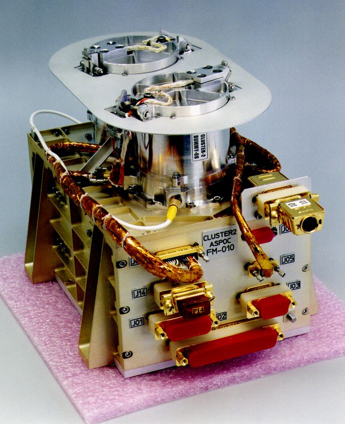
1290                                                               K. Torkar et al.: Active spacecraft potential control for Cluster

reach values > 50 V, as already shown by GEOS and ISEE               2   Operating principle
observations (Pedersen et al., 1983).
   Sensors for both ions and electrons suffer from high space-       If one neglects ion currents and the secondary emission, and
craft potentials since the particles are accelerated or deceler-     assumes the orbit-limited case, when the Debye length is
ated and their trajectories are modified in the sheath around        much larger than the body (a typical situation in the outer
the spacecraft. Some particles may not reach the sensor at           magnetosphere) then a spacecraft in sunlight, yet outside the
all. Most of the photoelectrons at energies below the space-         regions with extremely hot plasma, such as in an active plas-
craft potential are trapped in the sheath and eventually return      masheet, experiences a random electron current Ia0 from the
to the surface of the sensor, causing an additional disturbance      plasma to the satellite surface A which is assumed here to be
in the measurements and problems for the sensors.                    spherical. If the electron distribution can be approximated by
                                                                     a Maxwellian, one obtains
   The problems associated with spacecraft charging have                           s
been recognised very early (for reviews, see e.g. Grard,                    A        8kTe
1973; Whipple, 1981), and measures to improve the situa-             Ia0 = ne e                                                 (1)
                                                                            4        πme
tion for the particle instruments have been sought. A first
and necessary step consists of avoiding local (differential)         in the form given by Pedersen (1995) to the original equation
charging of spacecraft surfaces, particularly near the particle      developed by Mott-Smith and Langmuir (1926). For posi-
sensors by making the entire surface of the spacecraft con-          tive spacecraft potentials Vs , the plasma electron current is
ductive, including the solar panel which has to be coated by         further approximated by

indium-tin oxide. A second step is achieved by actively low-                         Vs
                                                                     Ia = Ia0 1 +
ering the potential. The rationale for active spacecraft poten-                      Ve
tial control has been established in the early 1980’s (see, e.g.                 kTe
Pedersen et al., 1983) and has triggered the installation of              Ve =                                                  (2)
                                                                                  e
instruments for the active control of the spacecraft potential
                                                                     where e, ne , me , Te are the charge, density, mass, and tem-
on several spacecraft. A plasma source has been installed on
                                                                     perature of the plasma electrons and k is the Boltzmann con-
the Polar spacecraft (Moore et al., 1995), whereas the princi-
                                                                     stant. The area A for a spherical spacecraft of radius R is
ple applied on Cluster has been tested earlier on the Geotail
                                                                     4π R 2 . With A = 20 m2 for a Cluster spacecraft and Vs = 0,
(Schmidt et al., 1995), Interball-Auroral (Torkar et al., 1998),
                                                                     the plasma electron current of Eq. (1) becomes numerically:
and Equator-S (Torkar et al., 1999) spacecraft.                                     p
   The instrument itself has been described earlier (Riedler et      Ia0 = 0.55ne kTe          [µA]                             (3)
al., 1997) in the version built for the first attempt to launch      where Ia0 is in µA, ne is in electrons cm−3 and kTe is in eV.
the Cluster spacecraft in 1996. For Cluster-II, several parts           The photoelectron current Ip is determined by the solar
of the hardware and software have been modified, but the             spectrum and the material properties of the surface. The
overall concept remains unchanged. The following sections            photoelectron saturation current density jps varies for dif-
provide a review of the instrument as it flies on board the          ferent materials, and between laboratory and in-orbit mea-
Cluster spacecraft, but novel aspects are the prime focus. The       surements. Feuerbacher and Fitton 1972) quote laboratory
last part of the paper presents first results from the mission.      data of jps for several spacecraft materials in the range be-
   The primary motivation for active spacecraft potential con-       tween 10 and 40 µA m−2 . Values up to 60 and 80 µA m−2
trol on Cluster is to permit an almost complete measurement          have been found in a study of ISEE-1, GEOS-1, GEOS-2 and
of the ambient plasma distribution functions both for elec-          Geotail potentials by Pedersen (1995). Part of this variability
trons and ions by PEACE (Plasma Electron And Currents                is explainble by different materials, surface finishes, and the
Experiment, Johnstone et al., 1997, this issue), and for ions        ageing processes in the space environment.
by CIS (Cluster Ion Spectroscopy, Rème et al., 1997), re-              Assuming a Maxwellian distribution of the photoelectron
spectively. Typical floating potentials of up to several tens of     population with a mean energy kTp , which is certainly only
volts obscure or render impossible the measurement of the            a very crude approximation, the current of photoelectrons
core of the ion-distribution function, which has a thermal en-       which finally escapes from the sunlit surface As into space
ergy comparable to the satellite potential. Densities calcu-         and thereby contributes to the current balance is for positive
lated from particle measurements show large discrepancies            spacecraft potential As :
from densities derived from wave experiments in these con-
                                                                                        −eVs

ditions. Measurements in eclipse made on ATS-6, SCATHA               Ip = As jps exp                                             (4)
                                                                                         kTp
and DE-1 have shown the appearance of previously “hidden”
ion populations, invisible in sunlight (Olsen, 1982).                Using experimental data from satellites, Pedersen (1995)
   When interpretating electron measurements, one encoun-            found a best fit to the current-voltage characteristics for Vs >
ters additional difficulties due to the contamination of the         10 V by a sum of two exponentials with jps = 80 µA m−2
data by photoelectrons entering into the sensor. Moment cal-         and 3 µA m−2 , and kTp = 2 eV and 7.5 eV, respectively, or

culations without any correction for spacecraft charging and                         −Vs                −Vs        h           i
photoelectrons would severely overestimate the density.              jp = 80 exp             + 3 exp                 µA m−2        (5)
                                                                                       2                7.5
K. Torkar et al.: Active spacecraft potential control for Cluster 1291
Fig. 1. Effect of an ion beam from 0 to 80 µA on the spacecraft potential of Cluster.
For Cluster with As = 3.9 m2 and at Vs = 10 V, the photo- – Particle measurements already increase considerably
emission current flowing into space, according to Eq. (5), is when the potential stays below 10 V and remains con-
Ip = jp · Vs = 5.2 µA. Hence, the equilibrium potential stant. An automated moment calculation on board can
will settle at Vs = 10 V when the current from the ambient easily be programmed to calculate only when energies
plasma, according to Eq. (3), exactly balances this current. exceed > 10 V. With spacecraft potential control, pho-
A Maxwellian plasma with 100 eV would achieve this at a toelectrons above this energy can be neglected, and the
density of ne ≈ 1 cm−3 . remaining errors in the calculation of the moments are
In order to maintain a potential ≤ 10 V for a more tenu- small.
ous plasma, an additional current has to be introduced into – A completely flat potential distribution across the space-
the system: a beam of ions at energies of 5 to 9 keV, as in craft sheath cannot be enforced in the presence of space
the present instrument, can provide this constant indepen- charges. Even if the potential of the spacecraft with re-
dently of any small potential drop in the spacecraft sheath. spect to the plasma, which is measured at a large dis-
The curve labelled “0 µA” in Fig. 1 shows the floating √ po- tance by the probes at the end of wire booms (tip-to-tip
tential of a Cluster spacecraft over the quantity n kTe distance for Cluster: 88 m), is known with high accu-
based on Eqs. (3) and (5) and, therefore, is only valid for racy (the remaining uncertainty refers to the potential
quiet conditions, i.e. no substorm-type conditions. By nor- between the probe and the plasma), there is no mea-
malising the abscissa, the temperature variations of the elec- surement of the potential as a function of distance from
trons have been eliminated apart from corrections due to the the spacecraft except for a few measurement points dur-
term (1 + Vs /Ve ) of Eq. (2). The dependence of the space- ing the wire boom release in the commissioning phase.
craft potential on the plasma temperature is small. This has Hence, the radial potential distribution remains a matter
been shown by Escoubet et al. (1997) for ISEE-1 data. Fig- of theory. Complete, numerical 3D models for the con-
ure 1 confirms the experimental results that the uncontrolled ditions of Cluster are not yet available. An analytical
spacecraft potential may approach +100 V in the magneto- study by Zhao et al. (1996), based on measurements on
spheric lobes. Furthermore, it shows the stabilising effect of board Geotail, has limited the height of a potential bar-
ion currents added to the system, even if the total ion current rier around a spacecraft with an ion beam for spacecraft
is well below the total photoemission current of the space- potential control to < 2 V.
craft. The figure also shows that the spacecraft potential con-
trol is most effective at low plasma density. – The electrical power consumed by the instrument in-
creases linearly with the ion current.
By doubling the ion current, the spacecraft potential is re-
duced by ≈ 2 V. The optimum ion current results from a – The lifetime of the ion sources decreases in proportion
trade-off between several points: with the current.1292 K. Torkar et al.: Active spacecraft potential control for Cluster
and 4.3%, respectively) has been chosen as the ion-source
charge material due to its low vapour pressure, which pre-
vents the contamination of the source insulators and ambient
spacecraft surfaces. On the other hand, the melting point at
156.6◦ C is high enough to prevent the melting of an unheated
source charge. The current-voltage diagram of the LMIS
shows a typical slope of 0.5 to 1.0 µA per 10 V increase
in the extraction voltage. The energy spread and the compo-
sition are important properties of the ion beam. Rüdenauer et
al. (1987) showed in the laboratory that the beam consists of
> 90% single-charged In+ with minor fractions of double-
and triple-charged ions and single-charged indium clusters.
The average charge number per emitted charged indium par-
ticle is 0.98, and the mass efficiency, i.e. the fraction of the
total mass taken by single-charged ions, at 10 µA is about
80%. The energy spectrum of the main In+ contribution
Fig. 2. Schematic plot of the principle of a needle type liquid metal is composed of a quasi-Gaussian component centred a few
ion source. volts below the electric potential of the tip, and of a lower en-
ergy tail extending more than 1 keV below the centre width.
The emitted In+ ion current shows some broadening of the
– The maximum current capability of the instrument energy spectrum with increasing currents at the extraction
drives the mass resources. electrode. At an emission current of 10 µA, the energy width
is 150 eV, but a low-intensity, low-energy tail down to more
Based on these considerations, one can determine the opti-
than 500 eV below nominal beam energy can be expected.
mum ion current, which will most likely lie in the range be-
The size of the reservoir (250 mg for Cluster) allows for up
tween 5 and 50 µA for a Cluster spacecraft.
to 4000 hours of nominal operating time at a 10 µA emis-
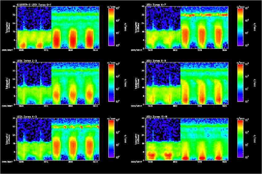
sion current for a single emitter. Figure 3 shows a single ion
3 Implementation for the Cluster mission emitter with its heater element. The indium reservoir and the
needle are kept at high voltage. The emitters are individually
3.1 The ion emitters and indirectly heated by a Pt100 wire resistor embedded in
a ceramic insulator tube. This scheme enables the source to
The ions are emitted by a “solid needle” type of Liquid Metal be heated from a grounded power supply, with the tip itself
Ion Sources (LMIS), using indium as a charge material. A remaining a high voltage. The mass of an emitter is 1.2 g
solid tungsten needle with a tip radius between 2 and 5 µm including the heater.
is mounted in a heated reservoir with the molten charge ma-
terial. The needle is wetted by an indium film. When a po- 3.2 The ion emitter modules
tential of 5 to 9 kV is applied between the needle and an ex-
tractor electrode, the electrostatic stress at the tip of the nee- In order to extend the operating time of the instrument and
dle acts against the surface tension forces of the liquid and to provide additional redundancy, eight emitters were com-
pulls the liquid metal towards the extractor electrode. The bined into one instrument, grouped into two so-called emit-
equilibrium configuration assumed by the liquid surface is ter modules powered by separate high voltage supplies. One
that of a Taylor cone (Taylor, 1964) with a total tip angle of module holds four individual ion emitters, which are op-
98.6◦ . The apex of the Taylor cone, in practice, reaches a erated one at a time. The individual emitters are embed-
diameter of 1 to 5 nm (Kingham and Swanson, 1984). Due ded in porous ceramic with extremely low heat conduction
to the small radius of curvature at the tip apex, the local elec- (< 5 × 10⁻⁴ W K−1 cm−1 ). In this way, the typical power
tric field reaches values of the order of volts per nanometre, consumption of the heater can be kept at 0.5 W. With 4000
which is sufficient for field ion emission. A broad ion beam hours of nominal operating time for a single emitter, two of
is formed (Fig. 2). The ion sources operate most efficiently them are more than sufficient to achieve the design goal of
in the current range from 10 to 30 µA, but higher currents 5000 hours per module, which is based on a two-year mis-
are supported for a limited time. sion with ≈ 50% operational coverage. The other emitters
Liquid Metal Ion Sources for spacecraft potential control serve as a back-up.
have been described before for the respective instruments on All emitters have a common extraction and focusing lens
board Geotail (Schmidt et al., 1993) and Cluster-I (Riedler arrangement with individual openings for each tip. It con-
et al., 1997). The basic principle (see, e.g. Mahoney et al., sists of a grounded extractor electrode, a focusing electrode
1969) has undergone a major redesign to qualify the sources at beam potential and a second ground electrode. These three
for space use (see Fehringer et al., 1997). For this instrument, electrodes constitute unipotential lenses for individual tips
indium (stable isotopes with 115 amu and 113 amu to 95.7% with the tip apex located in one focal point. The divergentK. Torkar et al.: Active spacecraft potential control for Cluster 1293
by the ambient plasma and is called the ion current or beam
current. With an increasing ion current, less photoelectrons
or plasma electrons, respectively, can return to or arrive at
the surface.
The total current is understood as the total current deliv-
ered by the high-voltage supply to the emitter. This current
includes the beam current and internal loss currents (e.g. the
current to the extraction and beam-focusing electrodes), and
is therefore always larger than the beam current. For small
to medium total currents (< 20 µA), the loss currents typi-
cally remain below 10%, but the percentage may increase for
higher currents.
Fig. 3. Photograph of an indium ion emitter. The reservoir at the 3.4 Overall configuration
right is heated by the heater element at the left. The total length is
19 mm. The ASPOC instrument is a single unit consisting of an elec-
tronics box and two cylindrical ion-emitter modules. Fig-
ure 4 shows the instrument with its two emitter modules
ion beam (opening angle ≈ 90◦ ) emitted from the tip is fo- mounted on top of the electronics box. The thermal blan-
cused by this lens into a nominally parallel beam. The cold ket of the spacecraft is attached to the plate on top of the unit.
secondary side of the high-voltage supply is connected to the The viewing direction is parallel to the spin axis to avoid spin
extraction and outer electrodes of the focusing lens, so that modulation of the currents. The wall thickness of the box is
no additional power supply or voltage divider is required for 0.8 mm. It carries four printed-circuit boards and a moth-
beam focusing. Since the beam shaping and focusing op- erboard. The electronic components have been selected, in
tics are purely electrostatic, the lens properties and the beam general, to withstand the predicted dose of ionising radiation
shape remain unchanged if the tip voltage (identical to focus- of ≈ 15 krad(Si) at the wall thickness of 0.8 mm. Additional
ing voltage) changes. spot shielding has been applied to a few less hard compo-
Metal tubes around the heater elements protect the heaters nents.
and their power supply, which is connected to the ground by
high-voltage strokes. With this grounding scheme, all possi- 3.5 Electronics
ble paths for high-voltage discharges are confined within the
high-voltage loop. Special attention has also been given to The instrument uses an 80C85 microprocessor (1) to oper-
minimise sputtering from one individual emitter to another, ate and control the ion-emitting system (high voltage and
and from an emitter to the isolators holding the electrodes. heater power), (2) to perform the start-up procedure of the
No ion can reach one of these surfaces without at least one emitters, and (3) to serve the interfaces to the onboard
reflection. data-handling and telecommand units, and to the electric-
In order to avoid oxidation, the indium in the LMIS should field instrument (EFW) and low-energy electron spectrom-
never be exposed to air or water vapour. An almost hermeti- eter (PEACE) which provide spacecraft potential data in real
cally closed volume has been designed (leak rate ≈ 8×10⁻⁸ ) time. Due to the low data rate (108 bit/s), both housekeeping
in which the emitters can be stored in a protective gaseous at- and science data are transmitted through the housekeeping
mosphere. It is opened after launch by a pyrotechnic piston channel. Complete status information is given within two
actuator which pushes away a hook that holds the spring- housekeeping data frames (≈ 10.3 s).
loaded cover plate in its locking position. The flight software is downloaded from PROM into
Due to the small volume of gas and the inevitable leakage, CMOS RAM when the instrument is turned on. A large part
the initial internal overpressure of 0.2 bar would disappear of the logic circuits that are not interfacing the spacecraft is
within about one year during storage on the ground and cause contained in a programmable gate array (FPGA). The DPU
air to enter from outside, thus contaminating the indium. For and the spacecraft interface logic cover two printed-circuit
the initial deliveries, the flight units were therefore equipped boards. The DPU has a watchdog timer. If a counter is not re-
with dummy emitter modules to be used during most of the set regularly by the program running in the DPU, it will per-
test activities before launch. These dummies were replaced form a full reset of the DPU and a reload of the programme
by the real emitter modules in the late exchange period before from the PROM into the RAM after 8 s.
the spacecraft were shipped to the launch site. The DC converter and the high-voltage unit each take up
one printed-circuit board. The DC converter provides three
3.3 Beam current and extractor current fixed voltages (+5 V, +13.5 V, −5 V) and a variable out-
put for the heater elements in the emitters. The high-voltage
In an ideal ion source, all generated ions would leave into unit can power one of the two emitter modules at a time in
space. This current loop is closed via the spacecraft surface voltage- or current-controlled modes. The voltage-controlled1294 K. Torkar et al.: Active spacecraft potential control for Cluster
Table 1. Instrument data summary
Quantity Value
Mass
Electronics box 1460 g
2 emitter modules with covers 360 g
Harness 50 g
Flange for thermal blanket 30 g
Total 1900 g
Size
Electronics box 187 × 157 × 95 mm
Emitter modules, closed 60 mm dia. × 75 mm
Overall 187 × 157 × 170 mm
Power
Average power 2.4 W
Peak power 2.7 W
Telemetry rate 108 bit/s
Design lifetime 10 000 hours at 10 µA
Beam characteristics
Species In+
Atomic mass 113, 115 amu
Energy ≈ 5 to 9 keV
Current max. 65 µA, design: 10 µA
Opening angle (half maximum) ±15◦
Fig. 4. Photo of the instrument. Direction along spin axis
mode is used during start-up of an emitter, before any ion
current is drawn. As soon as ion emission starts, the supply with Geotail and Equator-S has become available. It turns
is switched into current-controlled mode to ensure a constant out that the thickness of the indium film covering the emitter
current. The voltage and hence, the energy of the ions is of needles is a very sensible parameter. A thicker film enhances
secondary importance. The analogue monitors of the high the capability to emit large currents at moderately higher op-
voltage, the total output current at high voltage and the ef- erating voltage, but it increases the average ignition and op-
fective ion-beam current are provided. The latter measure- erating voltage. The production process of the emitters was
ment necessitates a special grounding concept for the emitter improved to ensure small deviations from the optimum thick-
supply unit. The power consumption consists of an almost ness.
constant component of ≈ 1 W for the DPU and the heating The laboratory test set-up was changed to allow for further
of one emitter filament (≈ 0.8 W), and a variable part which shielding of emitters against backsputtering from the walls of
is largely proportional to the emitted ion current. While 3 W the vacuum chamber.
peak primary power can be reached by design, the maximum A feature to limit the high-voltage applied to the emitter
power reached during nominal operations is 2.7 W, and an when operating in constant current mode was added to the
average value of 2.4 W primary power complies with the re- instrument software. When the voltage threshold is reached,
quirements on the ion current for spacecraft potential control the emitter is either turned off or a cleaning cycle is executed.
in the expected plasma environment. With this safety feature in place, the high-voltage capability
Redundancy is achieved by two separate high voltage cas- of the supply was set to 9.3 kV.
cades. , There are separate high voltage cascades including
3.7 Instrument data summary
the secondary side of the transformer, and the current and
voltage monitors for each module, whereas the digital pro- The main instrument data are summarised in Table 1.
cessing unit and the low voltage side of the high voltage sup-
ply are not redundant. The switching of high voltage between
modules is done by a latching relay at the primary side. 4 Operating modes
3.6 Changes since Cluster-I 4.1 Constant current mode
Since the original design of the ion emitters and the emit- The basic operating mode of ASPOC involves setting the to-
ter modules for Cluster-I and Geotail, some flight experience tal emitter supply current to some predetermined value basedK. Torkar et al.: Active spacecraft potential control for Cluster 1295
Fig. 5. Spacecraft potential control in constant current mode at 20 µA (bold line) and in feedback mode (dashed line).
on the spacecraft current-voltage characteristics and expe- (PEACE), and this information is used to adjust the emission
rience gained in the mission. Since the loss current inside current so that the spacecraft potential is kept at a desired
the instrument to the extractor electrode can normally be ne- value in a closed loop scheme. This mode is called feedback
glected, the constant total current mode at the same time pro- mode.
duces a constant ion beam current. The value of the current Probes 1 and 2 of EFW are always operated in volt-
can be set by time-tagged commands to vary according to the age mode to measure the electric field. EFW flight soft-
expected plasma environment along the orbit. At the same ware calculates the mean value of the unfiltered spacecraft
time, the current level must be sufficiently low to ensure that potential raw data measured between the spacecraft body
the spacecraft potential does not become negative. Experi- and probes 1 and 2, respectively. The resulting quantity
ence during the first seven months after launch proves theo- Vsc = −(V1 + V2 )/2 is sampled every second and sent to
retical expectations that negative charging events are unlikely the Digital Wave Processor (DWP) instrument, which com-
on the Cluster orbit. In fact, no significant negative charging bines it with operating mode information from the WHIS-
event has been observed so far. This constant total current PER sounder (Décréau et al., 1997) and transmits the product
mode has been chosen as the baseline mode for the Cluster to ASPOC via a dedicated serial, the digital Inter-Experiment
mission due to its robustness combined with sufficient scien- Link (IEL) interface.
tific performance. There is an alternative feedback mode using estimates of
There is another standalone mode that maintains a con- the spacecraft potential calculated from the low energy por-
stant current of the emitted ion beam rather than the total tion of the electron spectrum by the onboard processor of the
current fed into the ion emitter. This mode does not provide instrument PEACE.
any significant improvement over the previous mode, but in-
cludes the risk that high total currents are drawn from an Figure 5 illustrates the slight improvement of the feedback
emitter which produces an abnormally high internal current mode (dashed line) over the constant current mode (bold
to the extractor electrode. While such cases are unlikely, they line). The√figure shows the spacecraft potential over the
might, if they occur, significantly reduce the total lifetime of quantity (n kTe ), as in Fig. 1, but here in Fig. 5 the abscissa
this emitter. Therefore, this mode has not been selected as a is labeled according to density, assuming an electron temper-
the baseline mode. ature of 10 eV. In constant current mode that is set to 20 µA,
the potential would be limited to 6 V at low densities and de-
4.2 Feedback mode crease for densities higher than ≈ 0.3 cm−3 . In this figure
it is assumed that at n > 10 cm−3 , the ion emitter would be
In a more complex operating mode, a measurement of the turned off according to a time-tagged command. The result-
spacecraft potential is supplied to ASPOC by either the ing small variation in the potential in the transition region be-
electric-field experiment (EFW) or the electron analyser tween low and high densities (n ≈ 0.3 to n ≈ 10 cm−3 ) can1296 K. Torkar et al.: Active spacecraft potential control for Cluster
Table 2. ASPOC mode summary
Mode Description Ion current Typical duration
Standby Passive mode none No limit
Start-up Warm up, then ignite ion emitter zero, ending with short (< 1 s) 13 to 15 min
peak (I < 50 µA)
Feedback Control loop with spacecraft potential data from Variable No limit
EFW or estimates from PEACE
Constant Current Emission independent of spacecraft potential Constant No limit
Calibration Measure current-voltage characteristics Step function 2 to 10 min
Active experiments Ion beam experiments Step function No limit
be eliminated by operating the instrument in feedback mode 4.5 Standby mode
(dashed line), where the ion current is automatically set to
values between 0 and 20 µA in order to maintain a potential In standby mode, the instrument remains completely passive:
of 6 V. In the high density regime, where the spacecraft po- the high voltage, the ion-beam emission, and the heater fila-
tential eventually turns negative, the ion beam is turned off in ments of the emitters are turned off. The instrument proces-
both operating modes, automatically in feedback mode and sor only serves the interfaces to the spacecraft and the Inter-
by a time-tagged command based on predicted densities in Experiment Link, and produces housekeeping data. Standby
constant current mode. Such conditions are, however, rather mode is the power-on mode and also the contingency mode
exceptional for the Cluster orbit with a 4 × 19.6 Earth radii in case of problems with the ion-beam emission. The in-
geocentric distance. The active spacecraft potential control strument does not have permanent memory. Standby mode
loop has been successfully tested during the commissioning is, therefore, useful to keep parameters in internal mem-
phase (see Sect. 5.3). ory, which otherwise would have to be uplinked again af-
ter power-off. Standby mode is the default mode between
data-acquisition intervals within one orbit. The default mode
4.3 Test and commissioning mode
during perigee passes through the radiation belts is OFF.
For calibration and “active experiment” purposes, a so-called 4.6 Start-up of emitters
Test and Commissioning Mode has been defined. Its main
objective lies in the measurement of the current-voltage char- The indium reservoir of an emitter has to be heated before
acteristics of the spacecraft at the beginning and in regular in- high voltage can be applied. Depending on the ambient tem-
tervals throughout the mission, in order to look for changes in perature and the thermal coupling of an individual emitter,
the photoemission properties of the surface. In this mode, the it takes 13 to 15 minutes to reach the operational tempera-
ion current is stepped over a wide range, and the spacecraft ture of an emitter. The gradual temperature increase and the
potential is measured simultaneously by EFW. The length of turn-on of high voltage is performed autonomously by the in-
each step is 8 or 16 s, the equivalent of about 2 to 4 spin strument after one of the emitters has been selected and one
periods. of the active operating modes has been commanded. Imme-
diately after the onset of ion emission (I > 2.2 µA, the in-
strument switches into the commanded operating mode. Due
4.4 Hot standby mode
to limited resources, only one emitter can be heated at a time.
Whenever a change in the active emitter is required, the pre-
Occasionally the ion-beam emission may have to be turned vious emitter has to be turned off before the start-up of the
off in a pre-planned manner during time intervals varying new emitter can occur.
from a few minutes up to fractions of hours, depending on
the expected ambient plasma conditions or due to operational 4.7 Cleaning of emitters
requirements, for example, during the interference test cam-
paign, when this mode turned out to be very useful. In Hot As eight emitters are present in each instrument, it is obvi-
Standby mode, the ion emitter is kept at elevated temperature ously necessary to change the working emitter from time to
and the indium remains liquid in order to ensure immediate time. Four emitters are combined in a module with common
re-start capability. As soon as the high voltage is ramped up, electrodes, which poses a small risk of cross-contamination
the emitter ignites again at almost the same voltage as during between emitters. Material sputtered from the lens system of
the previous operation. the active emitter may accumulate on the passive emitters andK. Torkar et al.: Active spacecraft potential control for Cluster 1297
thereby increase the ignition voltage of the latter. Conditions Table 3. Selection criteria for ion emitters
generally return to normal after some minutes of operation
due to a self-cleaning effect of the active emitter. This self- Ignition voltage of the emitter < 8.3 kV
cleaning capability increases with the applied current. This
can be used as a precautionary measure against the possi- Operating voltage of the emitter < 8.0 kV
ble contamination of an emitter. The signatures are a slow Current efficiency > 90%
increase in the operating voltage, reflecting the higher flow
Power versus temperature char- 0.45...0.6 W at T ≈ 300◦ C
impedance of the liquid indium. The instrument software can acteristics of the heater
be set to monitor the operating voltage and to trigger a short
high-current peak (20 to 60 s, 50 to 80 µA) when the volt-
age exceeds a threshold. Alternatively, such “cleaning cy-
cles” may be performed by explicit time-tagged commands IEL are unfiltered raw data samples of the potential, which
and even as a preventive measure without any measurable contain some disturbances.
preceding change in voltage.
While the start-up of emitters at the beginning of data ac-
5 First results
quisition and during the switch-over to another emitter cause
short interruptions in the spacecraft potential control, occa-
5.1 Performance of emitters
sional “cleanings” would drive the potential to slightly lower
values, but the currents involved (< 80 µA) are not sufficient During the commissioning phase between launch and 21 De-
to drive the potential to negative values (see Fig. 1). cember 2000, the ion emitters in the four instruments have
been characterised, and the emitters to be used during nomi-
4.8 Technical mode
nal operations were selected. Table 3 lists the key parameters
Finally, a technical mode is available to perform low-level with the selection criteria for the nominal mission.
commanding for basic inspection of the instrument. A sum- A total of 87 start-ups of emitters was carried out in the
mary of operational modes is given in Table 2. commissioning phase, resulting in a ranking of emitters for
each of the spacecraft 2, 3, and 4. Up to 180 h of operation
4.9 Contingencies time for a single emitter were achieved, including the first
months of the nominal mission until 7 April 2001.
Possible failure conditions from external sources (e.g. an On 27 August 2000, on spacecraft 1, during the start-up
unexpected absence of spacecraft potential data in feedback of one of the emitters, a discharge occurred somewhere in
mode) or technical problems with the instrument (e.g. failure the high-voltage parts, therby damaging a multiplexer in the
of an emitter) may be grouped into three categories: emitter monitor circuit. The very unfortunate side effect of
this event was that further high-voltage operations of this in-
1. Failure of an ion emitter, strument became impossible.
2. Failure of the active inter-experiment link from
5.2 Effect on spacecraft potential
EFW/DWP or PEACE,
3. Disturbances by the WHISPER instrument in its active Figure 6 shows the spacecraft potential during commission-
mode. ing operations of spacecraft 2 on 13 September 2000, in red.
The spacecraft were located in the magnetotail at ≈ 23:00 LT,
Case 1 is detected autonomously by the instrument, which moving in and out the plasmasheet. The spacecraft were sep-
switches into the safe standby mode. Thereafter, contingency arated by ≈ 1000 km, primarily in longitude. In this time
actions will be taken from the ground. Case 2 is covered interval of about 3 h, two different emitters were operated on
by the instrument’s capability to switch into a back-up op- spacecraft 2. For comparison, the uncontrolled potential of
erational mode which does not rely on the inter-experiment spacecraft 1 is shown in black.
link. If any unexpected interruption of the spacecraft poten- From 20:03 to 21:05, emitter B2 was operated in constant
tial data flow occurs while ASPOC is in feedback mode, the total current mode. After one minute at 15 µA immediately
ion emission is kept at the last value for a few spin periods after start-up, the ion beam current varied slightly between 10
before the current is either turned off or set to constant value and 11 µA. The variation was due to minor changes in the ef-
(standby or stand-alone mode). ficiency. The dramatic reduction of the potential from values
As for case 3, it turns out that the WHISPER instrument > 20 V before emitter was turned on to 7–8 V is obvious.
in its active sounding modes changes the instantaneous mea- During this interval, the potential on spacecraft 1 peaks at
surement of the spacecraft potential. In its active mode as 40 V. Since the two curves for the potential follow each other
a relaxation sounder, the instrument WHISPER emits pulses closely when ASPOC is OFF, one can assume that the poten-
from the wire boom antennae with amplitudes up to 200 Vpp . tial of spacecraft 2 would have reached 40 V as well. The
These disturbances are successfully removed in the high res- large fluctuations in the uncontrolled potential are reduced to
olution data of EFW, but the data received by ASPOC on the variations of < 1 V on spacecraft 2.1298 K. Torkar et al.: Active spacecraft potential control for Cluster
ASPOC Operations on 13 September 2000 ASPOC Operations on 25 September 2000 10:35 - 16:42
50
45 15
40
S/C 1:
Spacecraft Potential [V]
35
uncontrolled
30
13
25
Potential of S/C 2 [V]
20
15
11
10
all data
5 constant feedback Feedback 9.0V
S/C 2: controlled, 10-11 µA 18 µA 22 µA
0
8 µA current mode mode
UT 19:30 20:00 20:30 21:00 21:30 22:00 22:30 23:00
9
XGSE -19.00 -18.90 -18.77 -18.64 -18.49 -18.33 -18.15 -17.97
YGSE 4.00 4.10 4.20 4.29 4.38 4.47 4.55 4.63
ZGSE 0.51 0.24 -0.03 -0.30 -0.56 -0.83 -1.10 -1.37
7
Fig. 6. ASPOC operation in constant current mode during commis-
sioning of spacecraft 2 on 13 September 2000. Positions of space-
5
craft 2 are given in Earth radii. 0 5 10 15
Ion Current [µA]
This stabilising effect on the potential is confirmed by the
Fig. 7. ASPOC operation in constant current mode and feedback
second operating interval from 21:27 to 21:40, using emitter mode during commissioning of spacecraft 2 on 25 September 2000.
B3 at 8 µA ion current. The deep drop of the potential from
40 to 15 V on spacecraft 1 is attenuated to a variation from
8.7 to 7.6 V.
The interval from 22:01 to 22:30, again with emitter B2 Szita et al. (2001, this issue). For completeness, their Fig. 4 is
and 10 µA is similar to the first one, but short excursions to reproduced here as Fig. 8. It shows data taken by the LEEA
higher ion currents of 18 and 20 µA, respectively, have been sensor of PEACE with anode 11, which sees electrons ar-
tested. With 22 µA, the spacecraft potential drops to 4.2 V. riving approximately along the spacecraft spin axis, from a
The potential data in this plot are understood as the poten- direction opposite to the solar panels. Thus, the contamina-
tial between the spacecraft body and the probes. In order tion by photoelectrons should be rather small. Nevertheless,
to obtain the potential of the spacecraft with respect to the the top panel, showing spacecraft 1 without potential control,
potential of the ambient plasma, the floating potential of the and the other panels for spacecraft 2 to 4 before 02:27 and af-
probes has to be added, which is typically 1 V or below. ter 05:13 on 7 February 2001, show significant signatures of
The objective of the feedback mode is to remove even the photoelectrons in the lower parts of the energy spectrograms.
small residual variations in the potential, similar to the one Between these times on spacecraft 2 to 4, the ASPOC ion
at about 21:35 on 13 September 2000. Figure 7 shows an- beam was set to 10 µA, thereby reducing the spacecraft po-
other example from the commissioning tests on 25 Septem- tential from the uncontrolled situation with ≈ 20 V to values
ber 2000. During a series of tests, the ion current was kept between ≈ 8.5 V at the beginning of the interval and ≈ 6.5 V
constant in many individual current settings between 5 and at the end. The residual variation is caused by an increas-
15 µA, shown with black symbols. Groups of points aligned ing trend in the total density, and possibly a simultaneous in-
in the vertical direction, e.g. at 4.5 µA, 6 µA and 12 µA, crease of the mean temperature. The high-energy tail of the
appear when the current was held over extended time inter- photoelectrons returning to the sensor appearing as a green
vals, while the ambient plasma conditions were changing, trace between ≈ 10 and ≈ 40 eV, merges with ambient elec-
and – as a result – the spacecraft potential was changing ac- tron features in the 100 eV range on board the uncontrolled
cordingly. The red symbols refer to an interval of 11 min spacecraft 1, whereas on spacecraft 2 to 4, the natural fea-
when the feedback mode with EFW was tested. The space- tures can be observed cleanly and with less modification of
craft potential was set to 9 V, and the instrument processor their energies when they pass the spacecraft sheath.
autonomously adjusted the ion current in the range from 7 Figure 9 illustrates that the electron distribution measured
to 9 µA. As a result, the residual variation in the potential at low energies is complex and requires further analysis.
is reduced to ±0.3V. A further reduction would have been Each panel shows an energy-time spectrogram of count rates
possible by increasing the basic resolution of the onboard from a polar sector of ≈ 30◦ resolution for a time interval
computation. of 5 spins (20 s). The energy scale is nearly logarithmic (step
8 is ≈ 5 eV, step 16 is ≈ 10 eV, step 24 is ≈ 20 eV, step
5.3 Effect on low energy electron measurements 36 is ≈ 80 eV, step 40 is ≈ 130 eV). The top left panels
show electrons arriving from the main engine; the lower right
The initial results of the spacecraft potential control on low panel shows electrons arriving from the opposite direction;
energy electron measurements are described in detail by and the bottom left and top right panels show electrons trav-K. Torkar et al.: Active spacecraft potential control for Cluster 1299 Fig. 8. Figure reproduced from Fig. 4 of Szita et al. (2001,this issue); data taken by the PEACE/LEEA in anode 11; for spacecraft 1 (top panel) to 4 (bottom panel); the ASPOC ion beam is active on spacecraft 2 to 4 between 02:27 and 05:13 on 7 February 2001. elling near the spacecraft spin plane. The maximum count electric domains, do not see any effect of the ion beam or the rates appear at the sunlit side. modifications to the spacecraft sheath caused by ASPOC. A The data have been taken during the interference campaign different situation is found with the electric field instrument on 16 December 2000. During the first two spin periods, (EFW, Gustafsson et al., 1997). Features of the ambient elec- ASPOC is still emitting a 10 µA ion beam. Electrons with an tric field may be attenuated in the measurements when AS- origin at the spacecraft are visible (green band) up to level 17 POC is active. The magnitude of the effect is highly variable (≈ 11 eV). Narrow vertical features occur when the sensor and obviously dependent on the ambient plasma density. sees the Sun. The spacecraft-probe potential is ≈ 9 V. When the ion beam is turned off, the potential jumps to ≈ 50 V, and the spectrograms show features extending up to this energy. 6 Discussion 5.4 Effect on other measurements 6.1 Beneficial aspects and side effects When ASPOC is active, the ion spectrometer CIS (Rème et The previous overview of initial ASPOC operations has al., 1997) can detect low energy ions which otherwise would demonstrated that the concept of spacecraft potential control be reflected in the spacecraft sheath. The count rates of major using a high-energy ion beam works satisfactorily: species H+ and O+ increase significantly. Features of minor species, such as He+ and He++ , may even disappear in the – The residual spacecraft potential follows very closely background noise as soon as ASPOC is turned off. the expectations based on model calculations and previ- As expected, wave instruments, both in the magnetic and ous experience,
1300                                                               K. Torkar et al.: Active spacecraft potential control for Cluster

Fig. 9. Energy-time spectrograms of the PEACE/LEEA sensor over five spin periods on 16 December 2000 covering an ON-OFF transition
of the ASPOC ion beam. The energy scale is quasi-logarithmic between ≈ 0 eV to ≈ 130 eV. Panels are for 6 different polar angles.

  – There are major beneficial effects on the low energy par-        Hence, collisions are extremely unlikely to occur. Photoion-
    ticle measurements of PEACE and CIS.                             isation of neutral indium and the attraction of these ions by
                                                                     negatively charged, non-conductive and shadowed surfaces
   A large number of theoretically possible side effects is def-     is negligible, since the photoionisation efficiency at 1 AU is
initely absent, as anticipated when the instrument had been          of the order of 10−7 , and a particle density inferred from
conceived. Riedler et al. (1997) list these non-effects.             the indium partial pressure of 10−15 mbar at a nominal op-
   The emission of a charged particle beam into a plasma is          erating temperature of 103 m−3 yields a negligible amount
a potential source of electrostatic and electromagnetic noise,       of In+ to be produced in the neighbourhood of the space-
but a numerical simulation study (Schmidt et al., 1992) dealt        craft. Finally, the gyro radius of the ions at a typical en-
with the plasma response to the emission of very weak ion            ergy of 6 keV is huge; it lies between 120 and 12 000 km
beams and found that the beam must be very cold for an               for magnetic fields of 1000 and 10 nT, respectively. Since
instability to be excited and only an adverse combination            the beam opening angle is ±15◦ , only a negligible number
of parameters would lead to wave growth. In the lobes,               of ions may return to the spacecraft. For perpendicular injec-
where spacecraft potential control is most valuable, the injec-      tion at B = 10 nT, the beam is spread over an area equivalent
tion only rarely occurs transverse to the magnetic field, and        to a circle of about 40 000 km in diametre, corresponding to a
the plasma conditions have the highest threshold for wave            flux of 5 × 10⁻⁶ cm−2 s−1 at Ie = 10µA. Both beam spread-
growth.                                                              ing or focusing have been neglected for this estimation. Fur-
   Chemical contamination by the ion beam, for example, by:          thermore, the CIS instrument is insensitive in the mass range
  – condensation of neutral indium in the vicinity of the ion        of indium.
    emitter,                                                            The observed effects causing problems for the wire-boom
                                                                     electric-field experiment EFW remain to be analysed. One
  – a return to the spacecraft of In+ ions after one or more         candidate hypothesis is based on the notion that the higher-
    gyrations,                                                       energy photoelectrons that no longer return to the spacecraft
  – the interaction of the ion beam with spacecraft surfaces,        where they had contaminated the particle measurements,
                                                                     now have to flow into the ambient plasma. This flow is asso-
could be ruled out for various reasons: the vapour pressure of       ciated with a reconfiguration (expansion) of the photo-sheath
indium is only 1 × 10⁻¹⁵ mbar at 250◦ C and the total surface        around the spacecraft, which is observed even at a 44 m dis-
from which indium evaporates is of the order of 1 mm2 for            tance. Whether or not the space charge carried by the ion
the active, hot emitter and about 9 mm2 for the surfaces at the      beam itself contributes to changes in the sheath to any signifi-
environmental temperature. In addition, the measured mass            cant and measurable extent for probe and particle instruments
efficiency sets an upper limit to the neutral indium emission        remains to be analysed as well. From the initial analysis of
of 3%. The typical mean free path length for neutral colli-          the particle data, one could not detect any features that would
sions exceeds 104 m if the pressure drops below 10−8 mbar.           point in this direction.
K. Torkar et al.: Active spacecraft potential control for Cluster 1301
6.2 Operational profile Neukirchner, U. Nischelwitzer, R. Wallner. We also deeply appre-
ciate the work of the Cluster Project Team at ESTEC, and the teams
During the first months of the mission, the apogee of the of Astrium, the operations centre at ESOC and the Joint Science
Cluster spacecraft was in the sunward sector, and major frac- Operations Centre which made the mission a success.
tions of the time were spent in the magnetosheath and in the Topical Editor G. Chanteur thanks K. Tswenda for his help in
solar wind. Only during intervals of < 10 hours between evaluating this paper.
perigee and outbound or inbound magnetopause crossings,
respectively, were more tenuous plasma regions crossed. In
order to avoid a waste of indium resources in regions where References
the ion beam would only marginally further reduce the space- Décréau, P. M. E., Fergeau, D., Krannosels’kikh, V., Lévêque, M.,
craft potential, the instruments were arranged so that they Martin, P., Randriamboarison, O., Sené, F. X., Trotignon, J. G.,
were only active between the exit from the radiation belts, up Canu, P., Mögensen, P. B., and WHISPER Investigators: WHIS-
until two hours after the nominal time of the outbound mag- PER, A resonance sounder and wave analyser: performances and
netopause crossing, and vice versa for the inbound sections perspectives for the Cluster mission, Space Sci. Rev., 79, 157–
of the orbits. 193, 1997.
Escoubet, C. P., Pedersen, A., Schmidt, R., and Lindqvist, P. A.:
Density in the magnetosphere inferred from ISEE 1 spacecraft
7 Conclusions potential, J. Geophys. Res., 102, 17 595, 1997.
Fehringer, M., Rüdenauer, F., and Steiger, W.: Space-proven in-
– The instrument ASPOC has demonstrated the capabil- dium liquid metal ion emitters for ion microthruster applications,
ity of reducing the spacecraft potential to values which Proc. 33rd AIAA/ASME/SAE/ASEE Joint Propulsion Confer-
already significantly improve the conditions for plasma ence, AIAA-97-3057, 1–11, 1997.
measurements, e.g. to ≈ 7 V (using 10 µA ion current) Feuerbacher, B. and Fitton, B.: Experimental investigation of
or ≈ 5 V (at 20 µA). photo-emission from satellite surface material, J. Appl. Phys.,
43 4, 1563–1572, 1972.
– ASPOC also reduces the natural fluctuations of the po- Grard, R. J. L.: Properties of the satellite photoelectron sheath de-
tential and thus provides a stable basis for the interpre- rived from photoemission laboratory results, J. Geophys. Res.,
78, 2885–2906, 1973.
tation of plasma measurements.
Gustafsson, G., Boström, R., Holback, B., Holmgren, G., Lundgren,
– A reduction of the spacecraft potential to ≈ 7 V is con- A., Stasiewicz, K., Ahlen, v, Mozer, F. S., Pankow, D., Harvey,
P., Berg, P., Ulrich, R., Pedersen, A., Schmidt, R., Butler, A.,
sidered to be a significant improvement for plasma mea-
Fransen, A. W. C., Klinge D., THomsen, M., Fälthammar, C.-G.,
surements in comparison with free floating potentials of
Lindqvist, P.-A., Chrinstenson, S., Holtet, J., Lybekk, B., Sten, T.
up to +50 V; therefore, the default ion current for nom- A., Tanskanen, P., Lappalainen, K., and Wygant, J.: The electric
inal operations has been set to 10 µA. field and wave experiment for the Cluster mission, Space Sci.
Rev., 79, 137–156, 1997.
– In order to maximise the scientific return from the in- Johnstone, A. D., Burge, S., Carter, P. J., Coates, A. J., Coker, A.
dium resources available, operations concentrate on re- J., Fazakerley, A. N., Grande, M., Gowan, R. A., Gurgiolo, C.,
gions with low plasma density, where the uncontrolled Hancock, B. K., Narheim, B., Preece, A., Sheather, P. H., Win-
potential would significantly exceed +7 V. ningham, J. D., and Woodliffe, R. D.: PEACE: A plasma electron
and current experiment, Space Sci. Rev., 79, 351–398, 1997.
– Tests of the “feedback mode” using the inter-experiment Kingham, D. R. and Swanson, L. W.: Mechanics of ion formation
data link from EFW to control the potential were suc- in Liquid Metal Ion Sources, Appl. Phys., A34, 123, 1984.
cessful. Mahoney, J. F., Yahiku, A. Y., Daley, H. L., Moore, R. D., and
Perel, J.: Electrohydrodynamic ion source, J. Appl. Phys., 40,
– No side effects of ASPOC on wave instruments were 5101–5106, 1969.
reported. Moore, T. E., Chappell, C. R., Chandler, M. O., Fields, S. A., Pol-
lock, C. J., Reasoner, D. L., Young, D. T., Burch, J. L., Eaker, N.,
– ASPOC affects the electric field measurements by EFW. Waite, Jr., J. H., McComas, D. J., Nordholdt, J. E., Thomsen, M.
While studies are ongoing, time-sharing of operations F., Berthelier, J. J., and Robson, R.: The Thermal Ion Dynamics
has been agreed. Experiment and Plasma Source Instrument, Space Sci. Rev., 71,
409–458, 1995.
– ASPOC operations do not completely cover the data ac- Mott-Smith, H. and Langmuir, I.: The theory of collectors in
quisition intervals of Cluster, which leaves room for in- gaseous discharges, Phys. Rev., 28, 727, 1926.
vestigations based on measurements of the uncontrolled Olsen, R. C.: The hidden ion population of the magnetosphere, J.
spacecraft potential. Geophys. Res., 87, 3481–3488, 1982.
Pedersen, A., Chapell, C. R., Knott, K., and Olsen, R. C.: Methods
Acknowledgements. We gratefully acknowledge the work of many for keeping a conductive spacecraft near the plasma potential, In:
people involved in hardware or software related to ASPOC: B. But- Spacecraft Plasma Interactions and Their Influence on Field and
ler, G. Fremuth, K. Fritzenwallner, F. Giner, H. Jeszenszky, B. Joh- Particle Measurements, Proceedings of the 17th ESLAB Sympo-
lander, C. Kürbisch, K. Kvernsveen, B. Kyrkjedelen, G. Laky, S. sium, ESA SP-198, 185–190, 1983.You can also read