NASA Marshall Space Flight Center Barrel-Shaped Asymmetrical Capacitor
←
→
Page content transcription
If your browser does not render page correctly, please read the page content below
National Aeronautics and                 NASA/TM—2004–213283
Space Administration
AD33
George C. Marshall Space Flight Center
Marshall Space Flight Center, Alabama
35812

                                         NASA Marshall Space Flight Center
                                         Barrel-Shaped Asymmetrical Capacitor
                                         J.W. Campbell, M.R. Carruth, D.L. Edwards, A. Finchum, G. Maxwell, and S. Nabors
                                         Marshall Space Flight Center, Marshall Space Flight Center, Alabama

                                         L. Smalley
                                         The University of Alabama in Huntsville, Huntsville, Alabama

                                         D. Huston, D. Ila, R. Zimmerman, C. Muntele, and I. Muntele
                                         Alabama A&M University

                                         June 2004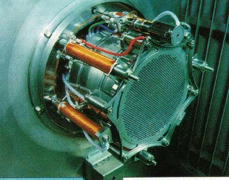
The NASA STI Program Office…in Profile

Since its founding, NASA has been dedicated to         • CONFERENCE PUBLICATION. Collected
the advancement of aeronautics and space                 papers from scientific and technical conferences,
science. The NASA Scientific and Technical               symposia, seminars, or other meetings sponsored
Information (STI) Program Office plays a key             or cosponsored by NASA.
part in helping NASA maintain this important
role.                                                  • SPECIAL PUBLICATION. Scientific, technical,
                                                         or historical information from NASA programs,
The NASA STI Program Office is operated by               projects, and mission, often concerned with
Langley Research Center, the lead center for             subjects having substantial public interest.
NASA’s scientific and technical information. The
NASA STI Program Office provides access to             • TECHNICAL TRANSLATION.
the NASA STI Database, the largest collection of         English-language translations of foreign
aeronautical and space science STI in the world.         scientific and technical material pertinent to
The Program Office is also NASA’s institutional          NASA’s mission.
mechanism for disseminating the results of its
research and development activities. These results     Specialized services that complement the STI
are published by NASA in the NASA STI Report           Program Office’s diverse offerings include creating
Series, which includes the following report types:     custom thesauri, building customized databases,
                                                       organizing and publishing research results…even
• TECHNICAL PUBLICATION. Reports of                    providing videos.
  completed research or a major significant
  phase of research that present the results of        For more information about the NASA STI Program
  NASA programs and include extensive data             Office, see the following:
  or theoretical analysis. Includes compilations
  of significant scientific and technical data         • Access the NASA STI Program Home Page at
  and information deemed to be of continuing             http://www.sti.nasa.gov
  reference value. NASA’s counterpart of peer-
  reviewed formal professional papers but has less     • E-mail your question via the Internet to
  stringent limitations on manuscript length and         help@sti.nasa.gov
  extent of graphic presentations.
                                                       • Fax your question to the NASA Access Help
• TECHNICAL MEMORANDUM. Scientific                       Desk at 301–621–0134
  and technical findings that are preliminary or of
  specialized interest, e.g., quick release reports,   • Telephone the NASA Access Help Desk at
  working papers, and bibliographies that contain        301–621–0390
  minimal annotation. Does not contain extensive
  analysis.                                            • Write to:
                                                         NASA Access Help Desk
• CONTRACTOR REPORT. Scientific and                      NASA Center for AeroSpace Information
  technical findings by NASA-sponsored                   7121 Standard Drive
  contractors and grantees.                              Hanover, MD 21076–1320
                                                         301–621–0390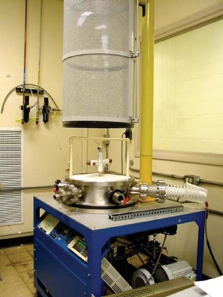
NASA/TM—2004–213283

NASA Marshall Space Flight Center
Barrel-Shaped Asymmetrical Capacitor
J.W. Campbell, M.R. Carruth, D.L. Edwards, A. Finchum, G. Maxwell, and S. Nabors
Marshall Space Flight Center, Marshall Space Flight Center, Alabama

L. Smalley
The University of Alabama in Huntsville, Huntsville, Alabama

D. Huston, D. Ila, R. Zimmerman, C. Muntele, and I. Muntele
Alabama A&M University

National Aeronautics and
Space Administration

Marshall Space Flight Center • MSFC, Alabama 35812

June 2004
                                       i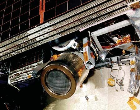
Acknowledgments

    The noteworthy contributions to the NASA Marshall Space Flight Center Barrel-Shaped Asymmetrical Capacitor
    by the following individuals and organizations that helped make this Technical Memorandum possible are greatly
      appreciated: James McGroary, Lisa Hughes, Vernotto McMillan, Steve Roy, Jeff Cameron; Rodney Bradford,
   United Applied Technologies; The University of Alabama in Huntsville; Dr. Al Sanders, the University of Tennessee;
           Francis Canning, Institute for Scientific Research, West Virginia; Oak Ridge National Laboratories;
                                              and Alabama A&M University.

                                                   TRADEMARKS

    Trade names and trademarks are used in this report for identification only. This usage does not constitute an official
            endorsement, either expressed or implied, by the National Aeronautics and Space Administration.

                                                     Available from:

NASA Center for AeroSpace Information                                                National Technical Information Service
7121 Standard Drive                                                                                  5285 Port Royal Road
Hanover, MD 21076–1320                                                                               Springfield, VA 22161
301–621–0390                                                                                                 703–487–4650

                                                             ii
TABLE OF CONTENTS

1. INTRODUCTION ........................................................................................................................          1

2. SYNTHESIS .................................................................................................................................    2

3. DESIGN DERIVATION ...............................................................................................................             11

4. BASIC PHYSICS .........................................................................................................................       16

5. EXPERIMENTAL RESULTS ......................................................................................................                   22

6. VACUUM TESTING AND RESULTS ........................................................................................                           30

7. THEORETICAL IMPLICATIONS ..............................................................................................                       32

8. FUTURE RESEARCH AND APPLICATIONS ...........................................................................                                  33

9. SUMMARY AND CONCLUSIONS ............................................................................................                          45

APPENDIX A—OUTREACH EFFORTS ..........................................................................................                           47

APPENDIX B—PRINCIPAL INVESTIGATOR BACKGROUND ...................................................                                                 49

REFERENCES ...................................................................................................................................   51

                                                                         iii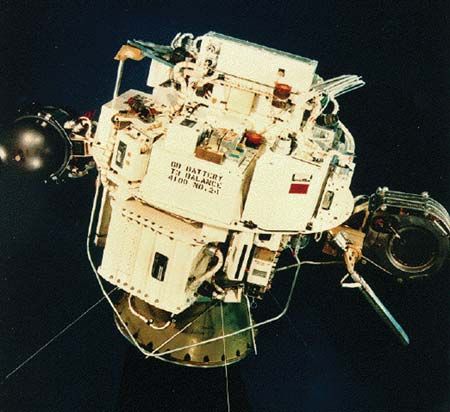
LIST OF FIGURES

 1.    NACAP derivation is based solely on the tremendous volume of information
       and data found in the public domain .................................................................................                     2

 2.    SERT I spacecraft ..............................................................................................................          3

 3.    SERT II flight experiment .................................................................................................                4

 4.    SERT II spacecraft .............................................................................................................          4

 5.    NSTAR thruster .................................................................................................................          5

 6.    UK–10 ion thruster ............................................................................................................           6

 7.    XIPS at Boeing Satellite Systems .....................................................................................                    6

 8.    Japanese ETS–VI ion propulsion ......................................................................................                     7

 9.    Modified J-series thruster ..................................................................................................              7

10.    Drawings from Townsend Brown’s 1928 public domain British patent illustrating
       a multiplate idea and a general cylindrical configuration ..................................................                              10

11.    Drawings from Townsend Brown’s 1960 public domain patent, illustrating a basic
       flat asymmetrical capacitor and rotary platform concept ..................................................                                10

12.    Derivation of the lifter from Townsend Brown’s basic flat asymmetrical
       capacitor ............................................................................................................................   11

13.    Rolling the Townsend Brown flat asymmetrical capacitor into a barrel shape
       provides the basic NACAP innovative configuration .......................................................                                 12

14.    NACAP derivation/synthesis engineering design options evolution ................................                                         13

15.    Anode design examples .....................................................................................................              13

16a.   Examples of various NACAP designs ...............................................................................                        14

16b.   Examples of potential NACAP applications .....................................................................                           14

                                                                     iv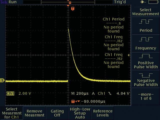
LIST OF FIGURES (Continued)

16c.   Other asymmetrical capacitor design examples ................................................................                          15

17.    Coulomb’s law is applicable to the NACAP .....................................................................                         17

18.    Example of Coulomb’s law ...............................................................................................               17

19.    Maxwell’s equations are applicable to NACAP operation ................................................                                 18

20.    Rocket example of conservation of momentum ................................................................                            19

21.    Illustration of mean free path ............................................................................................            20

22.    Experimental hardware configuration—NACAP model Alpha ........................................                                          22

23.    NACAP experimental hardware rotary test bed ................................................................                           23

24.    NACAP experimental model Alpha mounted in a rotary test bed ....................................                                       24

25.    The near NACAP vicinity .................................................................................................              24

26.    NACAP spin-down data ....................................................................................................              25

27.    NACAP RPM versus voltage showing upper and lower operating
       boundaries .........................................................................................................................   26

28.    NACAP average current versus voltage ............................................................................                      26

29.    Thrust initiating prior to test bed rotation .........................................................................                 28

30.    Cylindrical asymmetrical capacitor modules under high potential for producing
       thrust with Trichel pulses observed ...................................................................................                28

31.    Cylindrical asymmetrical capacitor modules under high potential for producing
       thrust with Trichel pulses observed ...................................................................................                29

32.    NACAP performance loss as pressure decreases ..............................................................                            30

33.    Vacuum lab configuration ..................................................................................................             31

34.    Closeup of two NACAPs mounted in an experimental rotational test bed
       for vacuum testing .............................................................................................................       31

                                                                     v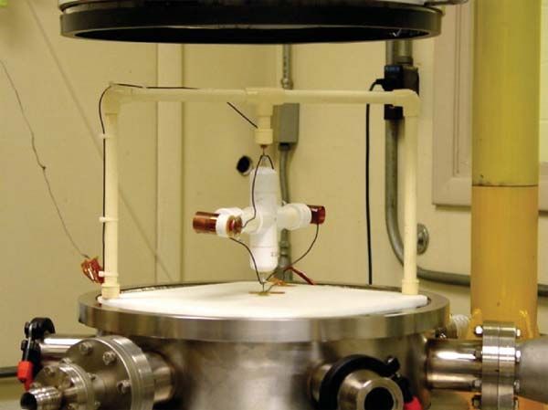
LIST OF FIGURES (Continued)

35.   Shrouded NACAP for producing thrust under high voltage in space ...............................                                       33

36.   A shortened shrouded NACAP configuration example for producing thrust
      under high voltage in space ...............................................................................................           34

37.   Additional anode configurations for NACAP I .................................................................                          34

38.   Additional anode configurations for NACAP II ................................................................                          35

39.   Basic view of performance and weight reduction design improvement for
      two-dimensional asymmetrical capacitor modules under high potential for
      producing thrust .................................................................................................................    35

40.   Another shrouded NACAP configuration for producing thrust under high
      voltage in space III ............................................................................................................     36

41.   Another shrouded NACAP configuration for producing thrust under high
      voltage in space IV ............................................................................................................      36

42.   Shrouded NACAP nested configuration for producing thrust under high
      voltage in space V .............................................................................................................      37

43.   Enclosed anode hybrid thruster configuration of NACAP for producing thrust
      under high voltage in space ...............................................................................................           38

44.   Enclosed anode hybrid thruster configuration of NACAP for producing thrust
      under high voltage in space with anode options gas tube/anode innovation I ..................                                         39

45.   Enclosed anode hybrid thruster configuration of NACAP for producing thrust
      under high voltage in space with anode options gas tube/anode innovation II .................                                         39

46.   Enclosed anode hybrid thruster configuration of cylindrical asymmetrical
      capacitor for producing thrust under high voltage in space III .........................................                              40

47.   Enclosed anode hybrid thruster configuration of cylindrical asymmetrical capacitor
      for producing thrust under high voltage in space with anode options gas tube/anode
      innovation IV .....................................................................................................................   40

48.   Front view of two-dimensional NACAP configurations for producing thrust
      under high voltage in space ...............................................................................................           41

                                                                   vi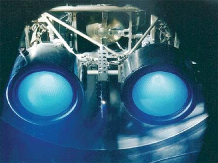
LIST OF FIGURES (Continued)

49.   Side view of two low-drag concepts of a two-dimensional asymmetrical capacitor
      for producing thrust under high voltage in space ..............................................................                          41

50.   Illustration showing that adding a current/voltage controller may significantly
      enhance operational performance ......................................................................................                   42

51.   Enclosed anode hybrid thruster configuration with variable anode/cathode
      separation ...........................................................................................................................   43

52.   Evan Frank’s award-winning science fair project ..............................................................                           48

                                                                    vii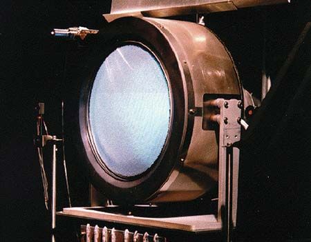
LIST OF TABLES

1.   Sampling of Townsend Brown’s patents illustrating the tremendous amount
     of information available in the public domain ....................................................................   9

2.   Collision frequency and mean free path comparison ..........................................................         29

                                                          viii
LIST OF ACRONYMS AND ABBREVIATIONS
ETS engineering test satellite
LeRC Lewis Research Center
MHD magnetohydrodynamics
mlb millipound
MSFC Marshall Space Flight Center
NACAP NASA Barrel-Shaped Asymmetrical Capacitor
NSSTC National Space Science Technology Center
SERT space electric rocket test
STP standard temperature and pressure
TM Technical Memorandum
U.S. United States
XIPS xenon ion propulsion system
ixNOMENCLATURE
b initial angular velocity at t =0
d rotor moment arm
dNACAP NACAP diameter
I moment of inertia
Iarm moment of inertia of rotary test bed arm
Iaxle moment of inertia of rotary test bed axle
In moment of inertia of N elements forming a complex shape
INACAP moment of inertia of NACAP
Isp specific impulse
Itotal total moment of inertia of NACAP mounted in rotary test bed
k =1.38×10⁻³ J/K
larm length of rotary test bed arm
lNACAP length of NACAP
m slope of curve
marm mass of rotary test bed arm
maxle mass of rotary test bed axle
mi ith mass
mNACAP NACAP mass
NA Avogadro’s number
P pressure
PT total momentum
R =8.31 J/mole K
rarm radius of rotary test bed arm
xNOMENCLATURE (Continued)
raxle radius of rotary test bed axle
rNACAP radius of NACAP
T temperature
t time
t1 first time
t2 second time
Tmax maximum thrust
TNACAP NACAP thrust
V voltage
v molecular average speed
r
vi velocity of the ith particle
α angular acceleration
θ angle
λ mean free path
τ torque
τR total resistive torque
τT torque due to thrust
ω angular speed
xiTECHNICAL MEMORANDUM
NASA MARSHALL SPACE FLIGHT CENTER BARREL-SHAPED
ASYMMETRICAL CAPACITOR
1. INTRODUCTION
Generating thrust in air with no moving parts and no conventional propellants, the NASA
Barrel-Shaped Asymmetrical Capacitor (NACAP) offers the potential for future aerospace applications.
Optimization engineering and evaluation testing are required to determine whether the technology may
compete successfully with other more mature propulsion technologies. These technologies include liquid
and solid rocket propulsion; various electric propulsion approaches; and turbofan, turbojet, and propeller
propulsion in air.
This Technical Memorandum (TM) provides a background and context for the technology
and includes a description of how the NACAP design was derived through synthesis solely from
the large public domain information base. The basic physics associated with the device’s performance
is reviewed, followed by a summary of experimental results obtained at Marshall Space Flight
Center (MSFC). In addition, recommendations for additional investigations are made, including both
experimental and theoretical paths. New configurations are recommended to increase performance
and extend operations into space.
12. SYNTHESIS
Drawing solely from a number of public domain information and data sources, the basic
synthesis process leading to the NACAP design may be understood. These sources are the extensive
public domain NASA and United States (U.S.) Air Force electric propulsion databases, the extensive
public domain Thomas Townsend Brown information and databases, and the laws of physics from
a number of physics textbooks studied in schools and universities across the U.S. and around the world.
In addition, commonly accepted aerospace requirements for safety, electrical robustness,
structural robustness, and systems integration formed an information base of design constraints that
were synthesized along with the public domain knowledge bases to derive the NACAP design (fig. 1).
Laws General Structural
of Physics* Design Requirements
for Aerospace
Applications*
NASA
and Air Force
Electric Propulsion
Database*
NACAP General Electrical
Derivation/ Design
Synthesis Requirements*
General Safety
Design Requirements
for Aerospace
Applications*
General Systems Townsend Brown
Integrations Design Database*
Requirements for
Aerospace Applications*
* Public Domain
Figure 1. NACAP derivation is based solely on the tremendous volume
of information and data found in the public domain.
2There is a tremendous volume of information and data available in the NASA and Air Force
electric propulsion information databases. The barrel-shaped configuration is common to many electric
propulsion systems. All such electric thrusters operate using electric and/or magnetic fields to accel-
erate charged particles and, hence, achieve propulsion through action/reaction; i.e., conservation of
momentum. All of these thrusters obey the basic laws of physics including Newton’s laws, conservation
of momentum, Maxwell’s equations, and kinetic theory.
For example, Talley published a report for the U.S. Air Force in 1991 covering an extensive
investigation into a specific asymmetrical capacitor design.1 He included vacuum testing in his
investigation and found that at 19 kV there was no detectable thrust in vacuum. This is one of several
independent investigations that have shown no detectable thrust in vacuum from asymmetrical
capacitors, as shall be described in this TM.
Other electric propulsion examples include the space electric rocket test (SERT) I at NASA
Lewis Research Center (LeRC) (figs. 2–4). This 10-cm mercury ion thruster was used in a suborbital
flight to successfully demonstrate ion beam neutralization in space. SERT II uses two 15-cm, 28-mN
mercury ion engines from NASA LeRC to demonstrate long-term ion thruster operation in space.2
Figure 2. SERT I spacecraft.
3Figure 3. SERT II flight experiment.
Figure 4. SERT II spacecraft.
The barrel-shaped configuration is used in a number of aerospace applications. The NASA New
Millennium Program first technology demonstration spacecraft (Deep Space 1) was planned to perform
an asteroid and comet flyby using the NASA Solar Electric Propulsion Technology Application
Readiness (NSTAR) ion propulsion system (fig. 5). The NSTAR engine is a 30-cm diameter ion thruster
using xenon as propellant. This engine requires a maximum thruster input power of 2.3 kW to provide
92 mN of thrust with a specific impulse (Isp) of 3,300 lbf-s/lbm (32,340 m/s).
4Figure 5. NSTAR thruster.
Deep Space 1 was launched from Cape Canaveral on October 24, 1998. During its primary
mission, it tested several advanced, high-risk technologies in space. Later, it encountered Comet Borrelly
and returned images and other science data.2
The UK–10 is a 10-cm diameter ion thruster that uses xenon as propellant. This thruster has
a divergent-field discharge chamber design and employs electromagnets rather than the permanent
magnets used in U.S. ion thrusters. At 660 W of input power, this thruster produces 25 mN of thrust
with an Isp of ≈3,350 lbf-s/lbm (32,800 m/s) and a thruster efficiency of ≈60 percent.2
AEA Technology in Culham, England, has been developing the UK–10 ion thruster (fig. 6)
as well as a larger version, the UK–25, and, more recently, the ESA–XX ion thruster as part of the UK
national program directed by the Space Department at the Royal Aircraft Establishment, Farnborough,
England. The UK–10 may be used primarily for satellite stationkeeping or possibly attitude control.
The ESA–XX ion thruster was developed in collaboration with other European companies. This 6-kW,
200-mN thruster is aimed at providing the propulsion requirements for future interplanetary space
missions as well as for orbit-raising applications near Earth.2
Using the HS 601HP bus, Boeing Satellite Systems, based in El Segundo, CA, markets a 13-cm
diameter xenon ion propulsion system (XIPS) for commercial satellites (fig. 7). The XIPS nominally
requires 440 W and produces an Isp of ≈2,600 lbf-s/lbm (25,480 m/s) with an efficiency of 51.3 percent.
In addition, Boeing has a higher power, 25-cm diameter, 18-kW thruster for use on their HS 702
spacecraft bus that produces 3,800 seconds Isp and 165 mN of thrust.2
5Figure 6. UK–10 ion thruster.
Figure 7. XIPS at Boeing Satellite Systems.
The ion propulsion system shown in figure 8 was developed to provide north-south station-
keeping for the Engineering Test Satellite VI (ETS–VI). Two 12-cm-diameter, divergent-field xenon
ion engines are shown. The spacecraft was launched in 1995 but never achieved operational orbit due
to a failure of the launch vehicle upper stage. The spacecraft was stranded in a highly elliptical orbit
passing through Earth’s radiation belts. All four ion engines were successfully tested before extensive
radiation damage to the solar arrays prevented further operation of the ion propulsion system.2
6Figure 8. Japanese ETS–VI ion propulsion system.
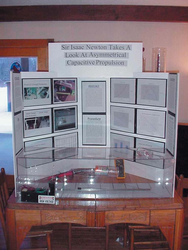
Figure 9 shows a demonstration of a 10-kW ion propulsion module assembled in 1987 at the Jet
Propulsion Laboratory in Pasadena, CA, for Mariner Mark II applications. Two modified J-series
30-cm diameter ion engines are shown on the module. Each engine is capable of operating at 5 kW
with a thrust on the order of 0.2 N and an Isp of 3,800 lbf-s/lbm with xenon propellant. The NACAP
in air promises much better thrust per power performance.2
Figure 9. Modified J-series thruster.
These examples indicate that another important part of the thruster or design synthesis process
is to factor in general aerospace requirements. For example, extended surfaces at high potential are
dangerous to ground crews and associated vehicle electronics and may severely constrain application.
Transportation vehicle charging is another concern both in space and air. Static discharges can wreak
havoc with onboard electronics, computers, and avionics. A barrel-shaped configuration should enable
convenient containment strategies such as thruster isolation on the tip of a wing or boom.
7Aerospace applications require light, yet structurally robust designs to withstand aerodynamic
loads in the atmosphere and/or launch and reentry loads. Fatigue considerations are also important both
in air and space. Thrust must be transferred from the propulsion system to the vehicle through a robust
structural interface. As with many other aerospace propulsion systems, a barrel-shaped configuration
enables a structurally robust design to meet these criteria.
Performance is highly dependent upon the electrical fidelity of the design. Working at high
voltages is difficult due to potential surface conduction on dielectric materials leading to electrical
breakdowns. A barrel-shaped configuration should be more electrically compatible with aerospace
applications and should eliminate any cathode edge effect losses.
Propulsion component design for aerospace applications must be integrated into a total system.
A barrel-shaped configuration follows the strategy seen for a diverse group of prior and existing
propulsion systems including turbine and turboprop airbreathing engines as well as solid, liquid, and
electric rocket engines. Hence, a barrel-shaped configuration enables optimum systems integration
while at the same time enabling sound safety and structural engineering requirements to be achieved.
Another important aspect of this synthesis is derived from the laws of physics as taught in
numerous texts across the U.S. Although the NACAP is relatively basic in design, in operation the
interactions between materials, particles, and fields are complex. The behavior of the NACAP can be
fully explained by the careful application of the laws of physics. This includes mechanics, dynamics,
Newton’s three laws of motion, the law of conservation of momentum, electricity and magnetism,
Coulomb’s law, Maxwell’s equations, thermodynamics, kinetic theory, relativity, and quantum
mechanics. These areas, when appropriately combined in a fluid context, constitute the field
of magnetohydrodynamics (MHD). The NACAP is an MHD device.
Townsend Brown’s extensive public domain information and databases are also part of this
synthesis (table 1). For example, some of his earliest work is reflected in his 1928 British patent detailed
in reference 3 (fig. 10). In this patent he teaches both flat plate and general cylindrical configurations.
Another example is one of Townsend Brown’s U.S. patents published in 1960 (fig. 11).4
In this patent he teaches that ion acceleration and the subsequent action-reaction are the basic physical
mechanisms producing thrust. He also teaches using a rotational platform as well as a basic flat
asymmetrical capacitor; the basic flat asymmetrical capacitor is the building block from which more
advanced designs may be synthesized. Asymmetry in this context refers to the geometrical asymmetry
between oppositely charged conductive elements of the capacitor. The basic flat plate capacitor as seen
in sophomore physics texts would be a counterexample of a symmetrical capacitor. Townsend Brown
also teaches that making the smaller conductive element positive provides greater thrust performance.
8Table 1. Sampling of Townsend Brown’s patents illustrating the tremendous
amount of information available in the public domain.
Country Patent Number Title Date Issued
Australia 49,960 Beneficiation of Gravitational Isotopes
Canada 675,966 Electrohydrodynamic Fluid Pump 12/10/63
726,958 Method for Beneficiation of and Devices Employing 2/1/66
Gravitational Isotopes
771,815 Electrohydrodynamic Sound Devices 11/14/67
876,356 Fluid Control System 7/20/71
France 1,207,519 Electrokinetic Methods 9/15/59
1,246,669 Electrohydrodynamic Pump
Germany W25839IVc/12E Beneficiation of Gravitational Isotopes
Great Britain 300,311 Method of Producing Force or Motion 11/15/28
20415/59 Beneficiation of Gravitational Isotopes
Holland 240,401 Beneficiation of Gravitational Isotopes
Italy 33/110 Beneficiation of Gravitational Isotopes
Japan 14819/34 Electrokinetic Methods
36–1066 Electrokinetic Methods 6/6/61
19917/34 Beneficiation of Gravitational Isotopes
Switzerland 427,509 Electrohydrodynamic Pump
United States 1,974,483 Electrostatic Motor 9/25/34
2,207,576 Method and Apparatus for Removing Suspended 3/11/47
Matter from Gases
2,417,347 Vibration Damper 3/11/47
2,949,550 Electrokinetic Apparatus 8/16/60
3,018,394 Electrokinetic Transducer 1/23/62
3,022,430 Electrokinetic Generator 2/20/62
3,187,206 Electrokinetic Apparatus 6/1/65
3,196,296 Electric Generator 7/20/65
3,267,860 Electrohydrodynamic Fluid Pump 8/23/66
3,296,491 Method and Apparatus for Producing Ions 1/3/67
and Electrically-Charged Aerosols
3,518,462 Fluid Flow Control System 6/30/70
Other Inventors 2,588,427 Condenser Charge Regulation
9Figure 10. Drawings from Townsend Brown’s 1928 public
domain British patent illustrating a multiplate idea
and a general cylindrical configuration.
Figure 11. Drawings from Townsend Brown’s 1960 public
domain patent, illustrating a basic flat asymmetrical
capacitor and rotary platform concept.
103. DESIGN DERIVATION
Figure 12 illustrates the building block approach for Jeff Cameron’s lifter innovation. Three
Townsend Brown basic flat asymmetrical capacitors are connected into a triangular cross section.
Any number of triangles may then be connected to form larger triangles giving the lifter design.
The triangular cross section tends to provide stability when lifting vertically. Note that the smaller
conductive element is usually made the anode.
Three Townsend Brown Flat Asymmetrical Capacitors
a a a a a a
i i i i i i
rr rr rr rr rr rr
- - - - - -
Top View
Four Triangles Combined Gives Lifter Configurations
Figure 12. Derivation of the lifter from Townsend Brown’s basic flat
asymmetrical capacitor.
Again starting with Townsend Brown’s basic flat asymmetrical capacitor and rolling it into
a barrel shape provides the fundamental NACAP design innovation (fig. 13). The basic NACAP then
forms the building block for a number of NACAP design innovations. Again, note that the smaller
conductive element is preferred for the anode. Of course, a number of experiments have been run
reversing the polarity of the capacitor. When the smaller conductive element is negative, reduced
performance is typically observed. Alternating, pulsed, and variable power remain to be investigated.
Certainly, some improvement in performance may be realized if a resonant pulse pattern could be found
that appropriately utilizes the electrodynamics and MHD characteristics of the thrust generation process.
11Gives the
Townsend Brown’s Fundamental
Flat Asymmetrical Rolled Into a NACAP
Capacitor Concept Barrel Shape Configuration
Conductor
Conductor
+
Dielectric
+
Dielectric
Air Air
– Conductor Conductor
–
Figure 13. Rolling the Townsend Brown flat asymmetrical capacitor into
a barrel shape provides the basic NACAP innovative
configuration.
The NACAP-extended derivations may focus on different variables depending on the
application. Maximum robustness for the aerospace environment may be the requirement or less
robustness and greater sparking resistance. Figure 14 illustrates some of these evolutionary options.
Clearly, for a given application, an optimization process is required to balance requirements appro-
priately. This is the primary thrust of MSFC NACAP research for a number of different applications.
Experimental model Alpha is the primary test hardware used in this TM. Experimental model Beta
that will be shown later and experimental model Gamma are follow-on devices providing greater
performance due to innovative design enhancements.
Since corona formation is one source of ions for the NACAP, optimizing anode design is an area
of continuing investigation (fig. 15). Again, depending upon the application, one configuration may be
preferable to another. The coronal production “ears” on experimental model Alpha are an innovation
courtesy of Jeff Cameron.
NASA has received two patents related to NACAP design innovations, US 6,317,310 B15
and US 6,411,493 B26 (figs. 16a–16c), and has a third patent pending that teaches additional design
modifications to enable operations in space.
12Maximum Solid Anode + Balancing Hollow Anode +
Robustness Solid less Solid
Dielectric Dielectric
robustness
with
Solid lighter Hollow
Cathode weight Cathode
_ _
Hollow Anode + Balancing
even less Hollow Anode +
Air robustness Air
Solid with lighter Solid
Dielectric weight, Dielectric (Experimental
greater Model Alpha)
sparking
Hollow resistance, and Hollow
Cathode better corona Cathode
_ initiation
_
Figure 14. NACAP derivation/synthesis engineering design
options evolution.
(Experimental (Experimental
Model Beta) Model Alpha)
More Aerodynamically Robust
Increased Corona
Figure 15. Anode design examples.
13Figure 16a. Examples of various NACAP designs.
Figure 16b. Examples of potential NACAP applications.
14Figure 16c. Other asymmetrical capacitor design examples.
154. BASIC PHYSICS
Superficially, the NACAP appears to be an electrostatic device. Coulomb’s law comes to mind
immediately. Figure 17 illustrates that the force between two charged objects is dependent upon their
separation as well as their charge. This basic theoretical description has been proven experimentally
many times.
Looking at an example of Coulomb’s law helps illustrate the promise of the NACAP due to the
substantive forces available from electrostatic charge interactions. In the example provided in figure 18,
the charges going through a typical 110-W household lightbulb in 1 s are collected and placed 1 m
from a collection of equal charge from another lightbulb. The electrostatic repulsive force predicted
by Coulomb’s law is 1 million tons. Although the current through the NACAP is much less than that
through a lightbulb, the separation is also much smaller than 1 m; hence, as described later in this TM,
the NACAP Coulomb forces may be substantial.
Although electrostatics plays a dominant role initially in the complex operation of the NACAP,
the emergence of a current implies moving charges which implies the existence of magnetic fields. One
future NACAP research area is the investigation and optimization of the magnetic field contribution
to the performance of the NACAP. Thus, one starts with Maxwell’s equations to begin a theoretical
description of the NACAP operation. Maxwell’s equations may be expressed either in integral form
or in differential form as shown in figure 19. Applying Maxwell’s equations to describe NACAP physics
is an area of theoretical investigation for the future.
Since the NACAP produces thrust, Newton’s three laws of motion also should be included in
a theoretical treatment. Newton’s first law states that an object remains at rest or in uniform motion in
a straight line unless acted upon by an external force. It may be seen as a statement about inertia, that
objects remain in their state of motion unless a force acts to change the motion. Any change in motion
involves an acceleration, and then Newton’s second law applies.
Newton’s second law, FNET = ma, applies to a wide range of physical phenomena; however, it
has limitations. It applies only where the force is the net external force. It does not apply directly when
the mass is changing, either from loss or gain of material, such as a rocket. Nor does it apply if the
object is traveling close to the speed of light where relativistic effects become siginificant. Nor does
it apply directly to the scale of the atom where quantum mechanics effects become significant.
Newton’s third law states that all forces in the universe are present in equal but oppositely
directed pairs. There are no isolated individual forces. For every single external force that acts on an
object there is another force of equal magnitude that acts back on the source that exerted that external
force. For internal forces, a force on one part of a system will be countered by a reaction force on
another part of the system. An isolated system cannot by any means exert a net force on the system
as a whole. A system cannot self-start itself into motion with purely internal forces to achieve a net
force and an acceleration; it has to interact with an object external to itself.
16Figure 17. Coulomb’s law is applicable to the NACAP.
Figure 18. Example of Coulomb’s law.
17Figure 19. Maxwell’s equations are applicable to NACAP operation.
Closely related to Newton’s laws is the law of conservation of momentum. The total momentum
of an isolated system is a constant. The vector sum of the individual momentums of an isolated system
cannot be changed by interactions inside the system. Thus only certain types of motions can occur in an
isolated system. If one element of a system is given a momentum in a given direction, then some other
element or elements of the system must also simultaneously be given exactly that same momentum in
the opposite direction. Conservation of momentum is an absolute symmetry of nature. Nothing in nature
is known that violates this fundamental law.
Defining the total momentum,
n r
PT = ∑ mi vi , (1)
1
the conservation of momentum then gives
PT (t1 ) = PT (t2 ) ; (2)
Hence,
n r n r
∑1 mi vi (t1) =∑1 mi vi (t2 ) . (3)
18A rocket is an excellent example of how the law of conservation of momentum may be used.
Using this law the rocket equation that predicts the speed of the rocket at any particular time in its
flight as a function of its mass may be derived. Based on equations shown in figure 20, if one measures
experimentally all of the parameters associated with the operation of a given rocket, one will find
those results to be in complete agreement with this theoretical development based on conservation
of momentum. This theoretical description has been confirmed many times by experiment.
Figure 20. Rocket example of conservation of momentum.
Next, by using relationships from kinetic theory, one realizes that the number of potential charge
carriers in the region near the capacitor is tremendous, offering the promise of a reservoir of tremendous
force from which to draw.
Figure 21 illustrates typical dimensions associated with kinetic theory for an ideal gas. Individual
molecules are exaggerated in size. A typical molecular diameter is 0.3 nm, an average molecular
separation is 3.3 nm, and an average molecular separation is about 10 times the molecular diameter.
The mean free path is 93 nm. Thus, for an ideal gas at standard pressure and temperature (STP) where
the pressure is 760 mmHg and the temperature is 0 °C, the mean free path is 310 times the typical
atomic diameter and 28 times the average molecular separation. The collision frequency is on the order
of 1010 collisions/s.
19Figure 21. Illustration of mean free path.
The ideal gas law is represented by PV = nRT, where R = 8.31 J/mole K. The molecular average
speed is
8kT
v= , (4)
πm
where k = 1.38×10⁻²³ J/K. The molecular mean free path is
RT
λ= , (5)
2πd 2 N A P
where NA = 6.02×10²³ and d ≈0.3×10⁻⁹m.
Magnetic and electric fields influence many natural and manmade fluids. They are used to heat,
pump, stir, and lift. Examples include Earth’s magnetic field that is maintained by fluid motion in
Earth’s core, the solar magnetic field that generates sunspots and solar flares, and the galactic field that
influences the formation of stars. Dynamics, electrodynamics, electrohydrodynamics, and MHD include
the study of the interaction of magnetic and electric fields, conducting and nonconducting bodies, and
fluids. Clearly, the relatively basic NACAP configurations give rise to extraordinarily complex
interactions between plasmas; charged and neutral bodies; charged particles and currents; and neutral
particles and flows that may be comprehensively described by an MHD formulation:
20∂ρ r
+ ∇ • ( ρu ) = 0
∂t
r
du r r
∂ = j × B − ∇p
dt
r r r r
(
j =σ E+u× B )
r
r r ∂E
∇ × B = µ0 j + µ0ε 0
∂t
r
r ∂B
∇×E =
∂t
r
∇• B = 0
r
∇•u = 0 . (6)
215. EXPERIMENTAL RESULTS
Three experimental hardware configurations were developed at the National Space Science
and Technology Center (NSSTC), NASA MSFC, and The University of Alabama in Huntsville.
Most experimental results were initially obtained using NACAP model Alpha. Models Beta and
Gamma served to confirm the results obtained in Alpha and verified that optimization could provide
higher performance. The Institute for Scientific Research located in Fairmont, WV, independently
investigated the NACAP and verified our findings (F. Canning, Institute for Scientific Research, Private
Communication, 2003–2004).
In figure 22, the region immediately surrounding the NACAP is a complex, extraordinarily
dynamic combination of intense electric fields; magnetic fields; carbon dioxide, water vapor, oxygen,
nitrogen and other trace gases in ion, atomic, and/or molecular states; ablation products; and plasma
(corona) interacting through multiple physical laws.
Thrust
Positive
Corona
Cathode (–) Dielectric
1.9 cm Anode (+)
5.1 cm
Figure 22. Experimental hardware configuration—NACAP model Alpha.
In his 1960 public domain patent, Townsend Brown teaches a rotational platform application.
A rotary test bed (fig. 23) was also selected for NACAP testing as it provides positive proof of thrust
generation, allows for an accurate measurement of the thrust, and enables testing in low-cost vacuum
chambers. There is no plan nor has there ever been an attempt by the authors to patent a rotational
test bed.
22Rotation
Experimental
Model Alpha
Thrust
Resistive Torque From Air
Drag and Bearing Friction
26.67 cm
230 g
Figure 23. NACAP experimental hardware rotary test bed.
Utilizing a rotary test bed enables the accurate calculation of the thrust by determining
the moment of inertia, measuring the angular velocity of the rotation, and by measuring the resistive
torque. The torque is a combination of air resistance and bearing friction. The moment of inertia may be
determined two independent ways. First, it can be calculated from the geometry and masses of the test
bed rotor and the two mounted NACAPs. The following equations show this approach:
Itotal = ∑ In = Iaxle + Iarm + INACAP . (7)
Using the parallel axis theorem,
1
2 2 1 2
Itotal ≈ maxle raxle +
marm rarm + marmlarm
2 12
1 2 1 2 2
+ mNACAP rNACAP + mNACAP lNACAP + mNACAP dNACAP . (8)
2 12
Second, the rotor may be suspended from a torsional pendulum. If the pendulum has already
been calibrated, the moment of inertia should be easily calculated from the harmonic motion of the
pendulum. Calibrating the pendulum using a known test mass is relatively straightforward as well.
A cylindrical weight may be used to calibrate the suspension fiber. A piano wire would be
a good choice. The moment of inertia of the weight is easily calculated from its mass and geometry.
By observing its torsional harmonic motion suspended from the wire, one may calculate the spring
constant for the wire. Once the spring constant is known, the moment of inertia of the rotor assembly
may easily be determined.
23Figure 24 shows two NACAPs mounted in an experimental rotary platform in preparation for
vacuum testing. Typical operating parameters are 27,000 V providing a steady state rotation of 60 RPM
and drawing 20 μA of current at STP.
Returning to Coulomb’s law example (fig. 25), NACAP peak thrust has been observed to be
a few millipounds at a peak current of 20 μA. If the analysis is performed using the observed parameters
from experimentation, the Coulomb forces for one second’s accumulative charge may be found to be
substantive. Clearly significant promise for greater performance is indicated.
• Number of moleculesnear vicinity = 9.04×10 21
• Equivalent Coulomb force20×10–6 A= 2,000 lb
• Equivalent Coulomb force2 NACAPs = 4,000 lb
Figure 24. NACAP experimental model Alpha mounted in rotary test bed.
Thrust
Experimental
Model Alpha
Positive
Cathode (–) Dielectric Corona
1.9 cm Anode (+)
Near Vicinity
5.1 cm
Figure 25. The near NACAP vicinity.
24Spin-down measurements indicate that the combined resistance due to drag and bearing friction
is essentially linear. Figure 26 shows example measurements taken from several experimental runs.
Angular velocity as a function of time is plotted. The rotor assembly with the NACAP at zero potential
is spun upward to 60–70 RPM. The rotor is then allowed to free spin while its angular deceleration due
to air resistance and bearing resistance is measured. The spin down may be approximated accurately
by a linear curve. This implies that the primary contribution to resistance to rotation is bearing friction
while air resistance at these speeds is only secondary.
Series 1 Series 4 Linear (Series 1)
Series 2 Series 5 Linear (Series 4)
Series 3 Series 6 Linear (Series 6)
70
60
50
Angular Velocity (RPM)
40
30
20
10
0
0 20 40 60 80 100 120 140 160
Time (s)
Figure 26. NACAP spin-down data.
Figure 27 illustrates a typical experimental dataset showing NACAP rotor RPM as a function
of voltage across the NACAP. As voltage is increased from zero, no rotation is observed until the thrust
exceeds the static friction bearing resistance. At this point, rotation initiates. Thrust initiates earlier but
is not measurable by this experimental approach until rotation begins. As the voltage increases so does
the thrust. At ≈28 kV for this particular NACAP configuration with extensive operating experience
under laboratory conditions, 60 RPM is achieved at steady state. If the voltage is increased above
this ceiling, random sparking events initiate. The experiment is terminated at this point to avoid damage
to the NACAP. Clearly, a design objective would be to raise the sparking threshold and increase thrust
at the same time.
2570
60
Angular Velocity (RPM)
50
40
30
20
10
0
1 10 20 30 40 50
Voltage Across Capactor (kV)
Figure 27. NACAP RPM versus voltage showing upper and lower operating boundaries.
Figure 28 shows the average current as a function of voltage for a typical NACAP experimental
run. While the instantaneous currents fluctuate dramatically, the average current is well behaved as is
evidenced by the smooth steady state motion of the rotor at optimum operating conditions. The wild
fluctuations in the instantaneous current indicate the complex MHD mechanisms at work on extremely
short timescales. An analysis of the instantaneous current is an area for future work.
Sparking Threshold
25
20
Current ( A)
15
10
5
0
0 5 10 15 20 25 30 35
Voltage Across Capacitor (kV)
Figure 28. NACAP average current versus voltage.
26By using the spin-down data, the thrust at steady state may easily be derived. The following
derivation indicates the approach:
From spin-down data, the change in angular velocity with respect to time appears linear;
b is intial angular velocity at t =0;
dθ
ω= = mt + b , (9)
dt
where m=slope of curve, a constant; the angular acceleration is
dω d 2θ
α= = 2 =m , (10)
dt dt
where ω is the angular speed and θ is the angle.
The total resistive torque, τR, is a combination of air resistance and bearing friction
d 2θ
τ R = Iα = I =Im , (11)
dt 2
where I is the moment of intertia. For constant torque τmax, the maximum thrust Tmax obeys
τ R = τ T = Tmax d , (12)
where d is the rotor moment arm. Hence, thrust may be calculated from the moment of inertia,
the slope of the curve, and the moment arm
Im
Tmax = . (13)
d
This derivation provides the following thrust levels for the NACAP steady state operation:
TNACAP = 14.54×10⁻³ N = 3.27×10⁻³ lb=3.27 mlb (14)
mechanical output τω
Thrust efficiency = = × 100% = 3.48% . (15)
electrical input VI
Efficiencies can probably be greatly enhanced through engineering improvements and represent
a design optimization research direction for the future. The J-series thruster is one electric propulsion
comparison. Operating in vacuum, it uses 5,000 W of power to produce only 45 mlb of thrust or
0.009 mlb/W. The NACAP in air produces 5.45 mlb/W. Hence, this is another indication of the promise
of the NACAP as compared to other electric propulsion devices.
27This analysis provides the thrust versus voltage chart shown in figure 29. Although rotation does
not begin until above 20 kV, other tests have shown thrust initiation to occur as low as 8 kV.
Sparking Threshold
4
3.5
3
Thrust (mlb)
2.5
2
1.5
1
0.5
0
0 5 10 15 20 25 30 35 40
Voltage (kV)
Figure 29. Thrust initiating prior to test bed rotation.
Trichel pulses associated with the NACAP were first observed at the NSSTC during operations
with the NACAP. These pulses indicate the extraordinarily dynamic nature of the plasma formed in
the local surroundings of the operating NACAP. The frequency of this cyclic behavior is ≈500 kHz
in the radiofrequency regime (figs. 30 and 31).
Figure 30. Cylindrical asymmetrical capacitor modules under
high potential for producing thrust with Trichel
pulses observed.
28Figure 31. Cylindrical asymmetrical capacitor modules under
high potential for producing thrust with Trichel
pulses observed.
Table 2 illustrates the change in collision frequency and mean free path in going from 1 atm to
vacuum. In vacuum, even though there is still an appreciable number of molecules present, a molecule
would probably collide with the wall of the vacuum chamber before it collides with another particle.
Collision frequencies are now on the order of 1/s. Clearly, loss of thrust is directly related to pressure
changes.
Table 2. Collision frequency and mean free path comparison.
Number of Molecules Molecular Mean
Pressure in Near Vicinity Free Path Collision Frequency Temperature
(torr) of NACAP (m) (collisions/s) (K)
760 9.04×10²¹ 1.02×10⁻⁷ 0.46×10¹⁰ 300
380 TBD 2.05×10⁻⁷ 2.29×10⁹ 300
10–7 1.19×10¹² 0.78×10³ 0.6 300
296. VACUUM TESTING AND RESULTS
No performance was observed from the NACAP under soft (1 torr) or hard (10–7 torr) vacuum
conditions. Figure 32 shows that NACAP performance rapidly falls to immeasurable levels as
the pressure is reduced. In hard vacuum even with potentials above 50 kV, there was no measurable
performance observed. Again, experimental runs were terminated upon reaching sparking threshold
to minimize damage to the NACAP and instrumentation. For example, one precision pressure gauge
was lost to electrical surges associated with sparking. Experiments included attaining normal RPM
levels at 1 atm inside the vacuum chamber and then gradually bringing down the pressure while
measuring changes in RPM. Measuring performance loss produced a very steep curve as pressure
was reduced. Upon bringing the vacuum chamber back to 1 atm, rotation immediately began again
and normal performance levels were once again attained. Figures 33 and 34 show the vacuum testing
configuration.
70
60
50
NACAP (RPM)
40
30
20
10
0
1×10⁻⁷ 1×10⁻⁵ 1×10⁻³ 1×10⁻¹ 1×101 1×10³
Pressure (torr)
Figure 32. NACAP performance loss as pressure decreases.
30Figure 33. Vacuum lab configuration.
Figure 34. Closeup of two NACAPs mounted in an experimental
rotational test bed for vacuum testing.
317. THEORETICAL IMPLICATIONS
A comprehensive treatment using an MHD formulation is the primary theoretical goal for future
work. This treatment will include multiple loss and inefficiency mechanisms. However, a simplistic
model may be used to calculate a rough upper bound. Neglecting kinetic motion of the ion and neutral
gas molecules, suppose that an ionized molecule is accelerated by the electric field over a distance
corresponding to the neutral mean free path until it elastically collides with a neutral. Further suppose
that this ion-neutral collision stops the ion completely with respect to moving in the electric field. By
conservation of momentum, the velocity of the neutral is now equal to the velocity of the ion just prior
to impact; using the conservation of energy, the velocity just before impact may be estimated. For dry air
at 1 atm and 80 °F, the mean free path is 1.02×10⁻⁷ m and the collision frequency is 0.46×10¹⁰ collision/s.
The ion velocity just prior to impact and the neutral velocity just after impact is 695 m/s. Adding cor-
rections for curved field lines, grazing collisions, and electrical losses gives a rough upper bound
for the steady state thrust from two NACAPs of ≈100 mlb. As with the Coulomb analysis, one sees that
the experimental result of a few millipounds is completely consistent with this upper bound. In other
words, the observed thrust levels seem easily obtained.
The tremendous number of potential charge carriers in the immediate region around the NACAP
coupled with multiple ionization mechanisms and high potential may easily provide the observed thrust
levels. In other words, charged particle acceleration acting in accordance with conservation of momen-
tum and Newton’s laws (action-reaction) are sufficient to explain NACAP operation. In addition,
the tremendous number of potential charge carriers in the immediate region around the NACAP offer
the promise of greatly improved performance through engineering design optimization.
328. FUTURE RESEARCH AND APPLICATIONS7
The NACAP may be enabled for operations in space by placing a cylindrical dielectric shroud,
capped at one end around the NACAP basic configuration (fig. 35). The shroud length may be varied to
provide optimum operation. A gas, such as air, nitrogen, oxygen, or argon, may then be provided to the
anode end of the NACAP. The NACAP then ionizes molecules and atoms in the flow and accelerates
them and subsequently the neutral fluid, producing thrust. Experimentation indicates that thrust may
be initiated as low as 8 kV for air. Using other gases may allow this threshold to be varied. Since thrust
levels are directly proportional to voltage across the capacitor, the NACAP should also be capable
of varying its thrust levels with a variable power supply. Thrust increases until reaching a sparking
threshold. Operating at voltages below this threshold increases lifetime. Varying gas flow may also
be a means of varying the thrust level.
High Voltage Power
Supply
Gas Supply
Vacuum
Anode Air Flow
Thrust
Cathode
Vacuum
Air Flow
Dielectric Vacuum
Figure 35. Shrouded NACAP for producing thrust under high voltage
in space.
33You can also read