Agrar-Pro-Steer Electro-hydraulic Positive Steering - Stapel GmbH
←
→
Page content transcription
If your browser does not render page correctly, please read the page content below
Agrar-Pro-Steer

Electro-hydraulic Positive
         Steering

                             Stapel
                             AgrarPro GmbH
                             25.01.2021
Operating and Maintenance
Instructions
                                            ProSteer

                 User Manual ProSteer
Version: A.0.3
Electro-hydraulic positive steering
Vehicle type:
Tandem                           AP-PS60e-21-A-B0RS; AP-PS60e-21-B-B0RS
Tridem                           AP-PS60e-32-A-BSRS; AP-PS60e-32-B-BSRS
Series:                          Up from 0001 to - - - -
First edition:                   25.01.2021

Dear customer,

Congratulations on the purchase of the electro-hydraulic positive steering system ProSteer
manufactured by AgrarPro GmbH. This product has been designed to considerably improve the
driving characteristics of combinations of towing vehicle and trailer. In order to maintain the
reliability of the equipment and to ensure a long lifetime, carefully read this manual and submit it to
new personnel to be trained as well. Damages arising from inobservance of the instructions provided
are not covered by warranty.

This       manual         must        remain        accessible         to      users       anytime.

                                                                                           Page 2 / 44
Operating and Maintenance
Instructions
                                                                  ProSteer

      Table of Contents
1     Introduction ..................................................................................................................................... 6

2     General Information ........................................................................................................................ 7

    2.1      Working Principle, Functions and Applications...................................................................... 7

    2.2      Safe and Appropriate Use........................................................................................................ 8

      2.2.1          Appropriate Use............................................................................................................... 8

      2.2.2          Rules for Prevention of Accidents ................................................................................... 8

      2.2.3          Improper Use ................................................................................................................. 10

    2.3      Specification .......................................................................................................................... 11

      2.3.1          Electric Parameters ........................................................................................................ 11

      2.3.2          Hydraulic Parameters .................................................................................................... 11

      2.3.3          Connectors and Interfaces ............................................................................................. 11

      2.3.4          Fluids ............................................................................................................................. 12

      2.3.5          Ambient Conditions....................................................................................................... 12

      2.3.6          Mechanical Parameters .................................................................................................. 12

    2.4      Environmental Protection ...................................................................................................... 12

    2.5      Expected Lifetime of the Equipment ..................................................................................... 12

    2.6      Safety ..................................................................................................................................... 12

3     Start-up .......................................................................................................................................... 13

    3.1      Preliminary Safety Measures ................................................................................................. 13

      3.1.1          Connection of the Drawbar Detector ............................................................................. 13

      3.1.2          Adjustment of the Drawbar Detector............................................................................. 13

      3.1.3          Electric Connections ...................................................................................................... 14

      3.1.4          Hydraulic Connections .................................................................................................. 14

    3.2      Switching OFF ...................................................................................................................... 14

4     Operation ....................................................................................................................................... 15

    4.1      Terminal – Type 1 ................................................................................................................. 16

      4.1.1          Emergency Button / Switching ON and OFF ................................................................ 16

                                                                                                                                      Page - 3 - / 44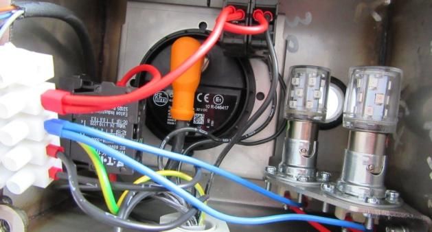
Operating and Maintenance
Instructions
                                                                  ProSteer

      4.1.2          Menu Structure .............................................................................................................. 16

      4.1.3          Drop-Down Menu ......................................................................................................... 19

    4.2      Terminal – Type 2 ................................................................................................................. 20

5     Description of Operating Modes ................................................................................................... 21

    5.1      Test Mode .............................................................................................................................. 21

    5.2      Road Mode ............................................................................................................................ 23

    5.3      Field Mode ............................................................................................................................ 23

      5.3.1          Slope .............................................................................................................................. 24

      5.3.2          Manual ........................................................................................................................... 24

      5.3.3          Speed Limits in Field Modes ......................................................................................... 25

      5.3.4          Errors in Field Modes .................................................................................................... 25

      5.3.5          Safe-Mode ..................................................................................................................... 26

    5.4      Troubleshooting..................................................................................................................... 27

6     Towing away / Manual Override ................................................................................................... 27

7     User Information ........................................................................................................................... 30

8     Maintenance .................................................................................................................................. 31

    8.1      Preliminary Safety Measures ................................................................................................. 31

    8.2      Service Points ........................................................................................................................ 31

    8.3      Adjustment of detectors......................................................................................................... 32

    8.4      Exchange of Signal Lamps .................................................................................................... 32

    8.5      Welding ................................................................................................................................. 33

    8.6      Regular Inspection by Technical Supervisory Association ................................................... 33

    8.7      Adjustment of Parameters ..................................................................................................... 33

    8.8      Acknowledgement of Service Message................................................................................. 33

9     Disposal ......................................................................................................................................... 35

10 Appendix – Error List.................................................................................................................... 37

    10.1     Test Report –Tandem A ........................................................................................................ 42

    10.2     Test Report – Tridem A ......................................................................................................... 43

    10.3     Declaration acc. to UN-ECE-R79 ......................................................................................... 44

                                                                                                                                      Page - 4 - / 44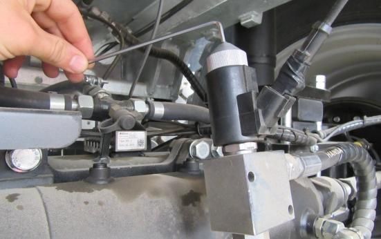
Operating and Maintenance
Instructions
                                                                ProSteer

Table of Figures
Fig. 1 Principle of the electro-hydraulic positive steering....................................................................... 7

Fig. 2 Data connector ........................................................................................................................... 11

Fig. 3 M12-connector, SUB-D & USB ................................................................................................ 11

Fig. 4 Hydraulic connections................................................................................................................ 11

Fig. 5 Greasing the K50 drawbar eye ................................................................................................... 13

Fig. 6 Drawbar detector - Drawbar....................................................................................................... 13

Fig. 7 Drawbar detector - Gooseneck ................................................................................................... 13

Fig. 8 Terminal ..................................................................................................................................... 16

Fig. 9 Tandem - Road ........................................................................................................................... 23

Fig. 10 Tridem - Road .......................................................................................................................... 23

Fig. 11 Tandem – Crab steering ........................................................................................................... 24

Fig. 12 Tridem – Crab steering ............................................................................................................ 24

Fig. 13 Tandem - Manual ..................................................................................................................... 24

Fig. 14 Tridem - Manual ...................................................................................................................... 24

Fig. 15 Plastic nut ................................................................................................................................. 29

Fig. 16 Manual override ....................................................................................................................... 29

Fig. 17 Bracket of axle angle detector .................................................................................................. 32

Fig. 18 Lamps within the case .............................................................................................................. 32

Fig. 19 Controller plug ......................................................................................................................... 33

                                                                                                                                   Page - 5 - / 44
Introduction

1 Introduction

The system ProSteer described in this document represents a valuable aid for improving the driving
characteristics of trailers and thus the traffic safety of the entire vehicle combination. Special programs
for difficult terrain, so-called Field Programs, are provided as well.

In the following, correct use, set up and operation are handled in detail.

In order not to impair the lifetime of the equipment, the maintenance instructions have to be followed
likewise. In any case of doubt, do not hesitate to consult our factory service.

Directions specified (at the front, at the rear, left or right side) always refer to the driving direction.

The system has been developed on the basis of „UN/ECE R79, appendix 6, chapter 3“.

                                                                                                   Page 6 / 44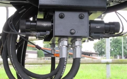
General Information

2 General Information

The steering system ProSteer is intended to support drivers and enhance traffic safety of vehicle
combinations comprising trailers in forestry, agricultural and also communal sector.

2.1 Working Principle, Functions and Applications

Besides a standard program particularly adapted to road travel, further programs are included to be
used in field applications. Selection takes place by means of the window of the terminal installed in
the driver’s cab. The structure of the entire configuration is shown in Fig. 1. (Note that in tandems, the
first trailer axle does not exist.)

                                                2.2           2.4
               1.2                                                                                    2.7
                                                2.3
                             2.1
                                                            3.3
                     V

                         D

                                                                                   3.5                      3.5
 1.1                                                  2.5
  M                                                                        3.4                        3.4
                                               P      3.2                  2.6                        2.6
                                               LS
                                               T                                                      2.7
                                             3.1

                                   Fig. 1 Principle of the electro-hydraulic positive steering

                                                      Main Components
 1.1   Hydraulic supply                                                          Hydraulic couplings:
       Power supply:                                                             P = Pressure line
 1.2                                                                    3.1
       Battery + Generator                                                       LS = Load-Sensing
       Terminal:                                                                 T = Tank line
       Emergency switch                                                 3.2      Hydraulic pressure filter
 2.1   Display                                                                   Steering block:
       Signal lamps                                                     3.3      Priority valve
       Release key                                                               Proportional valves
 2.2   Plug – Power supply                                              3.4      Steering cylinder
 2.3   Terminal board                                                            Open 2/2 way directional seat valve
                                                                        3.5
 2.4   Safety-Controller                                                         Free run valve
 2.5   Draw-bar angle detector
 2.6   Axle angle detector
 2.7   Speed sensor

Working Principle:
The electro-hydraulic positive steering has been designed for trailers -refer to Fig. 1- , and therefore
does not feature an own power supply. Hydraulic (1.1) and electric energy (1.2) is supplied from the
towing vehicle. Between towing vehicle and trailer, hydraulic couplings (3.1) and plugs (2.2 & 2.3) act
as interfaces. The terminal (2.1) installed in the driver’s cab, is used to switch ON and OFF the
electro-hydraulic positive steering, and to send release messages to the controller. A display for
visualization as well as two signal lamps for warning (integrated within the case), are provided. This
way the driver is always informed about the state of the system.
The steering system is connected to the safety controller accommodated within the switch cabinet
(2.4). Sensor and detector data obtained from sources (2.5-7) are processed here, in order to properly

                                                                                                            Page 7 / 44
General Information

adapt the steering angle on the basis of the currently selected program. Note that speed sensors (2.7)
are always installed on the last axle of the trailer.
A change of the steering angle is initiated by the steering block (3.3) comprising the priority valve,
which mainly supplies hydraulic oil to the steering system, directing residual quantities to other
hydraulic systems. The steering angle itself is changed by a proportional valve each, connected to a
steering cylinder (3.4). To enhance safety, each steering axle disposes of its own directional control
valve. The open valve (3.5), a so-called free run valve, interconnects the two chambers of the steering
cylinder. The axle therefore is enabled to move under the influence of external forces, i.e. it is self-
steering. The lateral forces are absorbed by the rigid axle.

2.2 Safe and Appropriate Use

This manual must be submitted to all persons involved with the equipment. Safety instructions must be
followed!

                Warning symbols: Passages within this manual important for safety of the user and
                persons in the surroundings, are marked by the symbol shown on the left.

2.2.1   Appropriate Use

The control features different steering programs: For road traffic, the standard mode is mandatory,
whereas programs to be used in fields are exclusively admissible in zones not subject to road traffic
licensing regulations. The mode should only be changed when the engine has been stopped.
The manufacturer assumes no liability for damages arising from applications contradictory to
appropriate use as defined in this manual. This includes described action to be taken for maintenance
and repair, as well as observance of additional operating instructions. If the machine is sold, leased, or
handed over to another organization, it must be accompanied by this manual and other relevant safety
information.
The equipment should never be used by persons unable to understand or to follow the operating
instructions, by novice drivers or by persons not disposing of a valid driving license.
These operating instructions have to considered as a complement to road traffic licensing regulations,
to regulations for prevention of accidents, to standards of occupational health and other safety
prescriptions, all of them to be respected as well.

   Manipulations and unauthorized modifications of hardware and software are not admissible!

2.2.2   Rules for Prevention of Accidents
Note that these prescriptions are essential not only for the driver himself, but also for third persons.
                  Warnings and safety labels attached to the equipment must remain clean and in
                  readable state.

                  Before starting to work, make sure that all functions and operating elements are
                  understood.

                  Documentation of the vehicle itself (in which the electro-hydraulic positive steering
                  unit is installed) must be observed likewise.

                                                                                                Page 8 / 44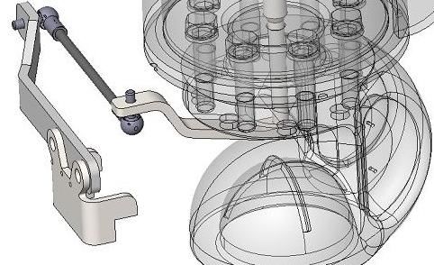
General Information
Operating authorization and operating instructions have to be considered as an
integral part of the equipment, and must be available at the place of action anytime.
When the machine is sold, leased, or handed over to another organization do not
forget to transmit the documents as well.
Pressure supply by the hydraulic system must amount at least to 180 bar, to be
adjusted by means of the priority valve. This valve is designed to support a flow of
150 l/min., with a flow of 50 l/min being required by the steering unit. A
corresponding type plate is attached in the front of the container.
Before starting repair or maintenance work:
Personnel must read this manual beforehand.
The motor of the towing vehicle must be switched off:
o Apply the brake.
o Remove the ignition key.
Separate the towing vehicle from voltage supply.
Apply the parking brake as well, if provided.
Wheels must be fixed by wheel chocks at the front axle.
For vehicles with LS hydraulics: Wait until the hydraulic pressure has
decreased.
Whenever the equipment is used in areas subject to road traffic licensing regulations,
the road mode (respectively safe mode) must be selected, by means of the terminal in
the driver’s cab.
Danger of crushing in the movement range of the wheels! During operation or
activation of the manual override, take care that other persons in the pivoting range
of the wheels are absent.
A corresponding warning label is attached to the container between the tires.
It is important to know that the steering system during selection of another mode,
adapts the orientation with respect to the towing vehicle, or runs slightly laterally
displaced. It is important that meanwhile other persons are not present in proximity
or within the working range of the vehicle.
Risks caused by the hydraulic system:
Fluid splashing off from the hydraulic system may give rise to severe skin irritations
or other injuries, infections etc. Call for medical assistance at once.
WARNING! Hot hydraulic lines and fluids may give rise to burns!
Danger of crushing in the pivoting range of the drawbar.
Only during coupling and uncoupling procedures, presence in this danger zone is
admissible. After completion, leave the zone immediately.
Page 9 / 44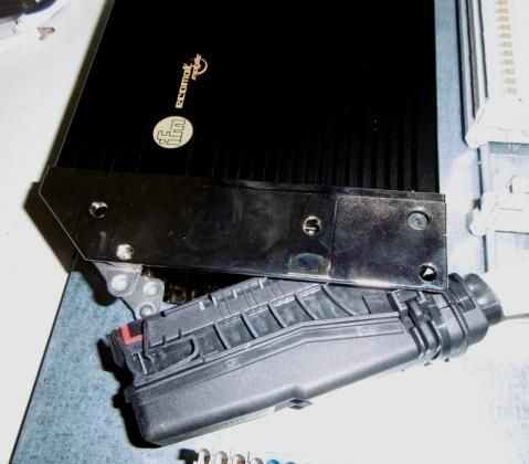
General Information

                As the emergency switch represents an essential part of the whole system, it must be
                accessible without difficulties, and remain operable anytime.

2.2.3   Improper Use

The system is equipped with safety features and devices, which should never be manipulated, bridged
or disabled. If one of these items proves to be defective, factory service must be informed without
delay.

                When driving in field mode and exceeding the speed limit of 30        just to change

                over to road travel mode, safety functions may be impaired. Corresponding action is
                therefore considered as improper use. Sudden braking action on the other hand
                changes the behavior of the electro-hydraulic positive steering unit, so the driver
                may lose control.
                Drivers should train braking action beforehand!

                Field modes should never be used on normal roads or in other zones subject to road
                traffic licensing regulations!

The manufacturer assumes no liability for damages caused by improper use.

                                                                                        Page 10 / 44
General Information
2.3 Specification
2.3.1 Electric Parameters
Voltage: 12/24 V
Current: 20 A max.
2.3.2 Hydraulic Parameters
Volume flow: min.: 50 for the electro-hydraulic positive steering unit
max.: 150 for other consumers
Pressure range: 180 bar max.
As the steering unit itself does not feature a supervision for the temperature of hydraulic fluid, it must
be monitored from the towing vehicle - otherwise correct function is not ensured.
In the case of very low temperatures, the steering behavior of the system is sluggish. Wait until the
temperature of the hydraulic fluid has sufficiently increased.
2.3.3 Connectors and Interfaces
Device connector at the drawbar console, to be
used for terminal.
Fig. 2 Data connector
SUB-D- and USB-connectors (as interfaces for
Service/Programming).
Fig. 3 M12-connector, SUB-D & USB
P
Hydraulic couplings:
LS
P
LS
T T
Fig. 4 Hydraulic connections
Page 11 / 44General Information
2.3.4 Fluids
Hydraulic system:
Oil class: HLP DIN 51524
Viscosity: 10-380 mm²/s
Lubricants for axles:
Grease as specified by the manufacturer of axle / drawbar eye
2.3.5 Ambient Conditions
Temperature range: –20°C to 60°C
The steering itself does not dispose of a supervision for the temperature of hydraulic fluid.
This function must be provided by the towing vehicle.
In the case of very low temperatures, the steering behavior of the system is sluggish. Wait
until the temperature of the hydraulic fluid has sufficiently increased.
2.3.6 Mechanical Parameters
Steering angle of wheels: Depends on the vehicle structure and the axle specification.
Maximum speed: 60km/h.
Tire size: Refer to the vehicle registration.
2.4 Environmental Protection
Environment should not be contaminated by hydraulic fluid, which is based on mineral oil. In the case
of a defect, it should be collected as prescribed, spilled oil must be removed.
2.5 Expected Lifetime of the Equipment
For 1000h / year → 12 years
- In the end, technical overhaul by AgrarPro GmbH is required.
Hydraulic hoses have to be exchanged after 6 years at the latest.
Hydraulic filters must be replaced after 1000 h or at least once per year!
2.6 Safety
For maintenance and repair, wear protective gloves.
The equipment meanwhile must be disconnected from power supply.
Page 12 / 44Start-up
3 Start-up
Connect the steering system as prescribed. Note that it has to be attached and
secured only in the specified positions. Act carefully while coupling and
uncoupling the unit.
3.1 Preliminary Safety Measures
Before initial start-up of ProSteer, mechanics of the drawbar angle detector must be adapted to the
towing machine. This measure should be repeated only after detachment of the coupling points of the
towing machine, or when another towing machine is intended to be used.
3.1.1 Connection of the Drawbar Detector
Drawbar with K50-clutch
In order to prevent excessive wear, the ball clutch
must be properly greased.
Safety pin
Inspection is necessary every time before
establishing the connection! Fig. 5 Greasing the K50-drawbar
eye
Hang up the ball clutch K50 of the drawbar detector, the
safety pin must engage.
Fig. 6 Drawbar Detector - Drawbar
Gooseneck
Connect towing machine and trailer by means of the two
M8-ball joints.
Each time before establishing attachment, check these ball
joints for wear! Fig. 7 Drawbar detector - Gooseneck
3.1.2 Adjustment of the Drawbar Detector
1. This adjustment requires alignment of towing
vehicle and trailer (i.e. they must be standing in
one line).
2. To fix the detector, insert M6 screw (Arrow).
3. Set up the detector mechanics by means of the
threaded rods.
4. Remove M6 screw (Arrow).
Page 13 / 44Start-up
3.1.3 Electric Connections
1. Plugs must be in correct state (undamaged, free of contamination).
2. Insert the plug.
3. The plug must properly be locked.
3.1.4 Hydraulic Connections
1. Switch OFF the machine.
2. Couplings and plugs must be in correct state (undamaged and clean). In case of need,
connectors must be replaced.
3. Establish hydraulic connections. Connectors can be identified by shape and size (refer to fig.
4):
a. T-Line
b. P-Line
c. LS-Line.
4. - It is important that hydraulic lines between the vehicles cannot be squeezed or subjected
to abrasion originating from moving parts.
3.2 Switching OFF
Before switching OFF, park the vehicle in a convenient place and wait until hydraulic pressure has
decreased. The trailer must be secured against rolling away (the wedges for that purpose always have
to be positioned at the rigid axle). In the end, all hydraulic hoses, electric lines and the mechanics of
the drawbar detector have to be separated from the towing machine.
Electronic components, e.g. plugs and terminals, should not be exposed to influences of weather.
Page 14 / 44Operation
4 Operation
The electro-hydraulic positive steering unit ProSteer together with its software has been developed
to offer convenient driving properties for different situations, thus increasing driving comfort and
safety.
When traveling on roads, the standard Road Mode ensures safe tracking and steering properties
meeting the requirements of current speed. The other modes are reserved for zones outside the scope
of the road traffic licensing regulations.
In inclined areas, the Slope Mode reduces drift when all steering axles are oriented in ascending
direction. Manual Mode enables all axles to be controlled in any direction in a targeted manner.
These modes are described in detail later in this manual, refer to section Description of Operating
Mod.
Caution! In Field Mode, the trailer laterally swings out. In case of large working width, check the
surroundings - the considerable motion caused by this effect should not give rise to collisions.
Safety information of this manual as well as the regulations for prevention of accidents
must be observed. Immediately replace safety labels attached to the vehicle, as soon as
they are damaged or no more identifiable.
All elements of the control, including the menu structure, must be known and understood,
before drivers are allowed to use the equipment.
During operation, ensure that other persons do not approach the danger zone close to the
vehicle.
As the steering behavior is influenced by the electro-hydraulic positive steering system,
sufficient space around trailers and optional working equipment in the surroundings must
be provided.
Do not underestimate the risk of crushing and injury by shearing caused by externally
actuated components (e.g. axles with hydraulic cylinders).
Never remove, disable or manipulate protective devices.
As the system is only admitted to a maximum speed of 60 km/h, it is automatically
switched OFF when this limit is reached.
After each restart, the functionality of electro-hydraulic positive steering is verified by the
test mode provided. If the vehicle is fully loaded, a certain test travel may be required, due
to the increased steering forces at the wheels.
The driving behavior must correspond to weather and road conditions.
The terminal in the driver’s cab has to be installed in the field of view of the driver, refer
to Fig. 8.
Page 15 / 44Operation
4.1 Terminal – Type 1
The steering systems Tandem and Tridem B are available also without display. In this case however,
field modes are not provided. Only emergency button and signal lamps are required
Emergency
button
Cover of signal
lamps
1-4
Function keys
Cross switch Release key
Fig. 8 Terminal
The cover at the left side of the display houses two signal lamps, Red and Green.
If the system is correctly working, the green lamp is lit. Red indicates an error condition, so the
system has been switched to Safe Mode. An alternating sequence at a frequency of 1 sec. signifies that
currently the test mode is active.
By means of the Release Key at the right side of the case, various functions can be activated / released.
4.1.1 Emergency Button / Switching ON and OFF
The emergency button of the ProSteer , refer to Fig. 8, is used for both, emergency stop as well as
normal switching ON and OFF. When pressing this button, it is latched in lower position, thus
enabling the steering system to be switched OFF in a safe manner. For restart, simply press the button
again.
After stop, the vehicle together with the trailer can be parked. Discharge of the battery of the towing
vehicle caused by the steering unit, is negligible.
As an alternative, the system can be switched OFF by disconnecting it from the power supply. If the
unit is not switched OFF by means of the emergency button, restart is accompanied by an error
message, which has to be acknowledged by the driver.
4.1.2 Menu Structure
The menu structure of the display is described in the following:
Page 16 / 44Operation
Initialization
During system start, the controller checks internal functions. The
display meanwhile shows INT – Initialization.
In the case of a previous error condition, failure etc., a warning
message appears on the screen.
Display – System Test
During verification of the functionality in
Tandem Tridem system test, the axle currently under
investigation is displayed, together with the
steering angle finally obtained. This way,
identified error conditions become obvious
at a glance.
From this mode it is also possible to select
the driving mode to be used afterwards.
Details are handled in chapter Test Mod.
Display - Road-Mode
If no Field Mode has been selected from System Test menu, the Road
Mode after completion is opened automatically. For purposes of
comparison, the speed value is shown.
Caution! This value is not intended to replace the tachometer of the
towing vehicle.
Selection of another mode
Pressing the Release Key for a
duration of 2-4 sec. opens the
selection window illustrated here.
It appears in the lower zone of the
screen. This menu remains
enabled for 10 seconds and allows
another driving mode to be
activated by means of the function
keys, 1-4, refer to Fig. 8.
The central picture shows the
buttons appearing on the display
during the change.
Page 17 / 44Operation
Display – Field Mode – Slope
Deflection
The desired steering angle is set up by means of keys 1 and 4. For this
purpose, three deflection points are predefined. Optimum set up takes
place by parametrization. The corresponding menu opens, when the
right arrow of the cross switch is pressed. The three predefined
deflection points may be adapted individually by means of the +/-
function. After completion, leave the menu by the left arrow of the
cross switch.
Parametrization
Pressing the double arrow key directs the axles in opposite direction.
It is important to know, that up from a speed of 20 km/h, the steering
angle is reduced, as detailed in chapter
Field Mod. This limitation of the steering angle can only be suspended
by pressing OK Key.
Display – Field-Mode – Manual
Tandem Tridem
The Manual Mode enables the steering
angle of each axle to be adapted
individually by means of the +/- keys,
regardless of the drawbar angle.
Use function keys 1 and 4 to specify the
axle intended to be configured.
Automatic Change to Road Mode
Up from a certain speed, the system automatically changes to Road Mode, due to reasons of safety.
The limit speed varies according to the different modes, as specified in chapter 5.3.3.
Never use Field Modes when driving in areas subject to road traffic licensing
regulations!
ALWAYS change over to Road Mode when entering corresponding zones. This
change has preferably to be performed, when the engine is in standstill!
ACHTUNG! Do not use the speed limit to change over to Road Mode. This feature is
intended merely as a safety feature. Performing a corresponding action when
traveling on a road, has to be considered as negligent behavior.
Page 18 / 44Operation
4.1.3 Drop-Down Menu
Apart from driving programs, the software features a drop-down menu (present in any driving mode),
accessible by the lower arrow on the cross switch. Leave this menu again by pressing the upper arrow.
This menu grants access to different functions provided by Left and Right arrow keys of the cross
switch.
Display – Errors
The first menu point opens the Error Memory. Errors contained can be
acknowledged (Quittieren), provided that they are no more active.
Display – CAN2
By means of the second menu, the CAN2-interface can be opened, so that
data may be transmitted from the steering unit to other controls.
Display – Information
Tandem Tridem
The third menu „Information“ is used to display
in real-time axle and drawbar angles, sometimes
useful for identification of errors and for set-up
of detectors, e.g. the drawbar detector.
Display – Service Menu
Stat. – Status:
The fourth menu informs about operating hours
and maintenance counter. ‘Trip‘ indicator
specifies the operating time of the unit, since
start-up.
Ver. – Verification:
Software version as well as the type currently
used are displayed.
Page 19 / 44Operation
4.2 Terminal – Type 2
Additional option: Not yet available.
Page 20 / 44Operation
5 Description of Operating Modes
Four main modes are provided, as described in the following:
1. Test Mode
2. Road Mode
3. Field Mode
a. Slope
b. Manual
4. Safe Mode
5.1 Test Mode
For reasons of safety, a test routine is launched during each start-up, to verify functionality of safety
controller, general actuators, valves, sensors and detectors including their specific mechanic actuators.
In case of an error, the assigned error number is displayed, so the reason of the problem can be
localized.
Before Test Mode is initiated, the control is in Safe Mode. Unintentional test routines are prevented by
specific start conditions. Test Mode however can be selected also after restart. It is important that the
trailer beforehand is in standstill. Then the routine can be launched either by accelerating to a speed of
1 km/h or by pressing the Release Key for a duration of 3 s.
In case of an error, the routine is aborted. The system switches over to Safe Mode, and up from that
moment, only emergency functions are available.
Check the surroundings before start-up. Unexpected presence of unauthorized
persons may give rise to injuries.
The same is valid when launching a test routine in the course a travel. Persons in the
path of the trailer are not admitted.
The run of the test routine is visualized by the signal lamps (red and green lamp
alternately lit at a frequency of 1 s) and the display – refer to chapter 4.1. Do not
CAUTION! leave the driver’s cab meanwhile. In case of need, quick reaction may be required.
For internal test, the vehicle should be in standstill (or moving at a speed of 3 km/h
max.).
Page 21 / 44Operation
To ensure a trouble-free test procedure, the following conditions must be met:
1. The routine can be launched in standstill or during a travel.
2. In the case of a loaded vehicle (with full axle loading), test execution during a travel may be
advantageous, in order to reduce steering forces.
3. The following points must be known:
a. In the case of a test in the course of a travel, the trailer temporarily may move slightly
laterally displaced to the towing vehicle.
b. Excessive steering movements meanwhile should be avoided.
c. Optimum driving speed amounts to 3km/h.
If an error is discovered during test, no more active steering movements are
possible – only self-steering.
Description of Test Procedure
This description may be useful to detect errors in the course of the routine. To each step, a specific
duration is assigned, during which the requirements have to be met. If the requirement cannot be met
within due time, Safe Mode is activated.
1. Test of Free Run Axle.
1.1. Initial pause.
Activation shortly after the locking axle.
1.2. Free run function, the axle is intended to be steered via centering – Free run valve in rest
position.
Steering movement of < 2,5° detected -> jump to 2.4.
Steering movement of > 2,5° detected -> go on with point 2.3.
1.3. Free run function, the control steers in opposite direction to 2.2 – Free run valve in rest
position.
Steering angle in identical direction to 2.2 -> No error
Steering angle in opposite direction to 2.2 -> Error.
1.4. Steering function, the control steers 3° beyond the centering (overshooting).
Steering movement is put into effect -> No error, < 3° or > 4° -> Error.
1.5. Steering function, the control centers the axle.
Steering movement is put into effect -> No error, < -1 or > 1° -> Error.
Page 22 / 44Operation
5.2 Road Mode
Tandem Tridem
BS2 BS2
+γ +γ
-25° +α2 -25° +α1 +α2
15° -15° 15°
-γ -α2 -γ -α1 -α2
BS1 BS1
Fig. 9 Tandem – Road Fig. 10 Tridem – Road
If during the test neither an error has been discovered by the system, nor a field mode activated by the
user, Road Mode opens automatically, and the steering angle of free run axle(s) is adjusted in
conformity with the drawbar angle.
Active steering this way achieved contributes to improve maneuverability on roads and the behavior of
the vehicle during shunting. Furthermore, thanks to permanent optimum orientation of the wheels,
wear of axles and wheels is reduced.
In order to prevent vibration of the trailer caused by steering movement, the steering angle is reduced.
Up from 20 km/h the steering angle with increasing speed is linearly lowered, so at 30 km/h the axles
are centered. When decelerating again, the angle automatically re-increases.
When slowing down from 30 km/h to 20 km/h, the complete steering angle is
released.
Whenever changing the steering mode (Road → Field or Field → Road), check the
ACHTUNG! surroundings beforehand to avoid accidents, as tracking of the trailer will change.
5.3 Field Mode
CAUTION!
Field modes should not be used on normal roads or in other zones subject to road
traffic licensing regulations!
Before selection these modes, the vehicle always should be in standstill.
If no error during test mode becomes obvious, the Field Mode becomes available as well, ready for
use.
Two possibilities are provided to activate Field Mode:
a) Already in the course of the Test Mode launched during restart. A selection menu is opened, and
after corresponding selection, the field mode automatically opens after completion of the routine.
b) During operation. To open the selection menu, the controller requires a signal of 2-4 s from the
Release Key. If the key is pressed for too long or not long enough, the menu remains closed. Press the
button again. Once opened, the menu remains accessible for 10 s. During this period, select one of the
Field Modes by means of Function Keys 3 & 4. For details, refer to chapter 4.1.
The following submenus are available:
Slope
Manual
Page 23 / 44Operation
Note that the possibility of selection is restricted by the driving speed. If the vehicle is driving too fast
for the corresponding mode, the selection is locked. Slow down before attempting to open the mode
again. If no mode is selected within 10 s, the window is closed, and a new release is required.
5.3.1 Slope
Tandem Tridem
BS2
BS2
+γ +γ
BG2 BG3
0° +α1 0° +α1 +α2
-15° 15° 15°
-γ -α1 -γ -α1 -α2
BS1 BS1
Fig. 11 Tandem – Crab Steering Abbildung 12 Tridem – Crab Steering
The Slope Mode is useful to reduce drift in inclined areas, by orienting the wheels of steering axle in
parallel to each other, with respect to the towing vehicle. The adjustment of steering angle of the
wheels takes place regardless of the drawbar angle by means of the display, refer to chapter 4.1.
As it is not possible to drive along curves in this mode, the change to Road Mode in corresponding
situations is always required. After completion of the turning manœuvre, the Slope Mode may be
enabled again. After turning, the axles must be steering in opposite direction. This is possible by
means of function key 3 (double arrow symbol).
Caution:
Meanwhile no persons should approach the danger zone.
The trailer may move slightly displaced to the towing vehicle.
The chassis may be subjected to warping, as soon as the steering axles are adjusted and the
rigid axle absorbs all lateral forces.
When this mode is left, always the current steering angle remains stored. After reactivation,
the system returns to the stored initial position.
Note that in case of breakdown of the steering system – Safe-Mode – no axle is actively
directed towards the slope.
In case of breakdown of the steering system – Safe-Mode – the trailer aligns behind the
towing vehicle.
5.3.2 Manual
Tandem Tridem
BS2
BS2
+γ +γ
BG2 BG3
0° +α2 0° +α1 +α2
-15° 15° 15°
-γ -α2 -γ -α1 -α2
BS1 BS1
Fig. 13 Tandem – Manual Fig. 14 Tridem Manual
This mode allows free orientation of the axles. Wheels may be adjusted independently and regardless
of the drawbar detector by means of the display, refer to 4.1.
This mode is reserved to extremely difficult situations impossible to handle by other modes, e.g. in
direct proximity to an embankment or a tree, or if the vehicle is blocked and must be exempted while
wheels are oriented in an inconvenient position.
Page 24 / 44Operation
It is essential however not to exert excessive stress on the chassis of the trailer during travel, caused by
inconvenient adjustment of the axles.
5.3.3 Speed Limits in Field Modes
To both Field Modes, speed limits are assigned, i.e. these modes are restricted to defined speed ranges.
If the field mode by mistake is still left active after acceleration, it is automatically disabled, and the
system switches over to Road Mode.
Caution: This function is a pure safety feature, not intended to replace regular change → refer to
chapter 4.1.
In order to prevent sudden change of the drive mode when unintentionally exceeding the limit speed,
the steering angle of the wheels is linearly reduced.
Road:
Up from 20 km/h the steering angle with increasing speed is linearly reduced, and at 30 km/h all axles
are centered. As soon as the control detects a speed value above 30km/h, the steering axles are no
more subjected to control. When slowing down, this restriction is suspended and the complete steering
angle becomes available again.
Slope Mode:
Up from 20 km/h the steering angle with increasing speed is linearly reduced, and at 30 km/h all axles
are centered. In this case however, the restriction during deceleration remains in force, and the current
steering angle is not changed. In order to return to initial steering angle, two possibilities are provided:
a) Pressing OK button on the display reestablishes the former steering angle, depending on the driving
speed. b) Use normal functions on the display to select a new steering angle. As soon as the control
detects a speed value above >30km/h, the Slope Mode automatically ends, and the system returns to
Road Mode.
The speed limit of 20 km/h must be respected - otherwise drift effect may be
increased, due to the reduction of the steering angle.
When simultaneously braking at a speed above 20 km/h and suspending the
limitation of the steering angle (OK key), the trailer instantaneously starts to run in
a trace laterally displaced to the towing vehicle.
Manual:
In Manual Mode, speed limits become active up from >4 km/h. The steering angle is lowered, and at
6 km/h all axles are centered. When increasing speed further, the system switches over to Road Mode.
When slowing down in Manual Mode, the steering starts to return to initial position.
5.3.4 Errors in Field Modes
An error occurring in Field Modes causes the system to switch over to Safe Mode automatically. The
free run axles up from that moment are subjected to self-steering. When working in inclined zones,
none of the axles is actively directed towards the slope anymore. This must be taken into
Page 25 / 44Operation
consideration. The knuckles of the steering axles cannot absorb lateral forces before arriving at the
limit stop, otherwise the trailer always aligns behind the towing vehicle.
In slope mode, it is important to know that after activation of the safety function,
only one axle remains actively steered towards the slope. This means: Slope
drift can only be used to a limited degree. (The rigid axle is requited to keep the
vehicle in its trace.)
5.3.5 Safe-Mode
In the case of system failure or breakdown, the controller automatically enables the Safe Mode, to
exclude risks for the driver himself and persons in proximity.
Significance of the Safe-Mode:
The Safe Mode can be considered as a fallback level defining a safe state, so the vehicle remains
always under control of the driver even in the case of an error. For this reason, the control ceases all
steering functions by switching back hydraulic valves to rest position. The green lamp is disabled, and
red warning lamp is lit.
As the CAN interface is located outside the system range, this communication with CAN bus remains
active, provided that this was not the origin of the problem. For this reason, error numbers may still be
displayed and used for determination of the source of the problem.
The recording of sensor and detector data may be continued as well, in order to maintain supply of
data to external controls. (Additional option).
Driving Behavior in Safe-Mode:
The safe state is established automatically. In order not to lose control in the case of an error, each axle
is subjected to self-steering – free run axle. During road travel, the tracking behavior of the tailer
remains identical, since track guidance up from that moment is ensured by the rigid axle. In Field
Mode, the tracking behavior corresponds to the state in Road Mode. In either case, no more axle is
actively steered.
The driver must be able to recognize the activation of the safety function at once. For this reason, the
signal lamps must be installed in his field of view.
Page 26 / 44Operation
Canceling the safety function:
1. Read out the error number from display or error list.
2. Switch OFF the steering system.
3. Localize and correct the error state.
4. Restart the system and acknowledge the error on the display.
5. Perform system test to check whether the problem is really solved.
a. Yes – The electro-hydraulic positive steering can be used again.
b. No – Consult factory service.
Activation of safety function:
For a list describing errors causing a change to Safe Mode, refer to the A of this manual. The numbers
specified correspond to the numbers appearing in the display for purposes of troubleshooting.
If none of the signal lamps is lit, this has to be regarded as an error as well!
It is recommended to reduce the speed to 30 km/h max., as no more active
steering is possible and free run axles may start to vibrate.
5.4 Troubleshooting
The trailer runs in a trace displaced to the towing vehicle, even though Road Mode has
Error:
been selected. Immediately press emergency button and stop the vehicle.
Action: Setting of axle or drawbar angle detectors may be incorrect.
Error: Excessive steering angle of rear axle when driving along curves. The vehicle swerves.
Action: Readjust angle detectors.
Defective signal lamp: Required information concerning the state of the system for the
Error: driver not available.
Error message: 0_0_31/32_X
Order and exchange signal lamps, refer to chapter Fehler! Verweisquelle konnte nicht
Action:
gefunden werden..
Error: Emergency switch does not latch, and the system cannot be switched OFF.
Action: Separate data plug or power supply, and move to next workshop.
Error: The system switches OFF completely; restart is impossible.
Action: Fuse or NO contact of the emergency switch may be damaged and has to be replaced.
Error: Even though the vehicle is moving, no speed value is shown in Road Mode.
Action: Signal from speed sensors absent. Drive to next workshop at once.
6 Towing away / Manual Override
Following situation: The steering system malfunctions and cannot be restarted. When attempting to
move the trailer backwards, the free run axles move in opposite directions and are therefore subjected
to warping. In this case, the manual override provided at the hydraulic valves, may solve the problem.
Page 27 / 44Operation
Before using this feature:
Press the emergency switch at the display, or separate the vehicle from power supply. Towing vehicle
and trailer must be secured against rolling away. In order to be able to adjust the steering angle, the
hydraulic supply must remain active, otherwise the axles cannot be adjusted.
Manual override is reserved to really critical situations. It is recommended to
attempt to solve the actual problem before making use of this feature.
No persons should approach the pivoting range of the trailer meanwhile.
Risk of burn – Hydraulic valves are hot, wear protective clothing.
In order to prevent unauthorized adjustment, after completion do not forget to
ACHTUNG!
reset the manual override at the proportional valves and remove it from
directional control valves.
For the positions mentioned in the following procedure, refer to the overview drawing, Fig. 1.
Page 28 / 44Operation
Procedure:
Secure the towing vehicle, the motor however must still be running.
CAUTION!
Components during operation may warm up.
Wear protective gloves!
1. Step – Preparing the action:
Take out the manual override from switch
cabinet, as shown in Fig. 16.
Unscrew the plastic nut from solenoid (Pos.
3.5).
Fig. 15 Plastic nut
2. Step – Unlocking directional control valve:
Unscrew the manual override, and turn in the set
screw down to the stop by means of a 3 mm
Allen wrench.
Do not tighten!
Repeat this procedure for all axles intended to be
adjusted.
Fig. 16 Manual override
3. Step – Adjusting the steering angle:
Set the desired steering angle by means of the
proportional valves (Pos. 3.3).
Manual override to A -> Axle is directed to
the left.
Manual override to B -> Axle is directed to
the right.
4. Step:
Remove the manual override, and refix the magnets by means of the plastic nut, as shown in Fig.
15, Place the manual override back into the switch cabinet.
Page 29 / 44Miscellaneous
7 User Information
The general state of the ProSteer is visualized by two signal lamps provided at the terminal.
If the system is correctly working, the green lamp is lit.
Red indicates an error condition, so the system has been switched to Safe Mode (the same is valid
when both LED’s remain dark).
An alternating sequence at a frequency of 1 sec. signifies that currently the test mode is active.
For further information concerning the display, refer to chapter Fehler! Verweisquelle konnte nicht
gefunden werden. Fehler! Verweisquelle konnte nicht gefunden werden..
Errors occurred remain stored in an error list, which can be viewed any time by customer service, for
purposes of diagnosis.
Page 30 / 44Miscellaneous
8 Maintenance
During maintenance and repair work, regulations for prevention of accidents must
be observed.
Never use high-pressure cleaners for electrical equipment like detectors or switch
cabinet.
A corresponding label is attached to the switch cabinet.
CAUTION!
Before starting to work, switch OFF power supply.
In case of injuries caused by hydraulic fluid, call for medical assistance at once!
8.1 Preliminary Safety Measures
The following conditions must be met:
The measure takes place in a safe and appropriate working area.
Vehicles are secured against rolling away.
The hydraulic system is unpressurized.
Steering system and towing vehicle are disconnected from power supply.
When working at the hydraulic system, oil is collected by a convenient container.
8.2 Service Points
For replacement of damaged items, exclusively use spare parts released by AgrarPro.
Daily measures, also during initial start-up:
No. Task Description
Axles must regularly be greased in conformity with the specification of
1. Lubrication
their manufacturer.
Adjustment of detectors has to be checked:
Angle Vehicle and trailer standing in one line →
2.
detectors - Axle and drawbar angle must be set to 0°.
- Wheels in straight orientation.
Page 31 / 44Miscellaneous
Service and annual maintenance
No. Task Description
Absence of damages:
Electronic 1) Check the case of the components for cracks and other damage.
3.
components 2) Cables should not be damaged or worn.
3) No corrosion should be visible on seals of plugs and contacts.
Check all hydraulic components:
1) Leak tightness of filters, hoses, tubes, couplings and valves must be
ensured.
Hydraulic 2) Verify hydraulic hoses for cracks or excessive wear.
4.
equipment Hoses should be replaced at the latest after six years.
3) No corrosion on hydraulic tubes.
4) Steering cylinders must be vented.
5) Replace pressure filters in the P line.
Mechanics of the detectors must be inspected:
Angle 1) Absence of corrosion
5.
detectors 2) Deformation
3) Worn bearings
The steering system must be checked for wear, according to the
specification of the manufacturer of the axles:
6. Axles
1) Spherical heads
2) Knuckles
8.3 Adjustment of detectors
Detector for axle angle:
2
1. Use the manual override to orient the axle in straight
direction, refer to chapter 6.
2. Detach mechanic assembly - 1. 1
3. Fix the detector by means of screw (M6x40mm) - 2.
4. Adjust and refix mechanic assembly - 1.
5. Remove fixing screw - 2.
Fig. 17 Bracket of axle angle detector
Detector for drawbar angle:
This procedure is described in chapter 3.1.2.
8.4 Exchange of Signal Lamps
The two signal lamps in the terminal can be
identified by a red and a green sticker, refer to Fig.
18. A damaged lamp must be replaced as soon as
possible.
Fig. 18 Lamps within the case
Page 32 / 44Miscellaneous
Only use lamps admitted for the steering system.
8.5 Welding
The following conditions must be met:
1. Welding is reserved to qualified welders.
2. Disconnect the control from power supply.
3. Detach the main plug from the controller, refer to Fig. 19.
4. Detach the plugs from speed sensor, axle angle and drawbar
angle detectors.
5. Attach the earth terminal of the welding unit directly at the
position to be welded.
6. Contact between welding electrode or earth terminal and
control elements of the electronics must be prevented.
7. The control elements must be protected against welding Fig. 19 Controller plug
spatters as well.
8.6 Regular Inspection by Technical Supervisory Association
During periodical inspection of the vehicle itself, the electro-hydraulic positive steering unit must be
inspected by the corresponding institution as well.
8.7 Adjustment of Parameters
Corresponding procedures are reserved to the customer service of AgrarPro GmbH.
8.8 Acknowledgement of Service Message
After start-up of the electro-hydraulic positive steering unit, the following message appears:
During maintenance and repair work, regulations for prevention of accidents must
be observed.
CAUTION!
Page 33 / 44Miscellaneous
After completion of service points, the service interval can be updated, as follows:
From the yellow triangle (cross switch), access to the Drop-Down
menu is possible.
Within this menu, service message 0-0-86-1 is issued. For
acknowledgement, use the cross switch to enter the parameter menu.
Within the Parameter Menu, change over to ‘Acknowledge Service’
by means of the fourth circular button.
Now press the third circular button once.
A counter starts to run for 10 s. If the maintenance counter is not yet
intended to be updated, abort the procedure by means of the third
circular button.
Page 34 / 44You can also read