Dinosaur Tectonics: A Structural Analysis of Theropod Undertracks with a Reconstruction of Theropod Walking Dynamics
←
→
Page content transcription
If your browser does not render page correctly, please read the page content below
Dinosaur Tectonics: A Structural Analysis of Theropod Undertracks
        with a Reconstruction of Theropod Walking Dynamics

                          Ole Graversen, Jesper Milàn, and David B. Loope1

  Geology Section, Department of Geography and Geology, University of Copenhagen, Geocenter Copenhagen,
                           Øster Voldgade 10, DK-1350 Copenhagen K, Denmark
                                         (e-mail: oleg@geol.ku.dk)

                                                         ABSTRACT
A dinosaur trackway in the Middle Jurassic eolian Entrada Sandstone of southern Utah, U.S.A., exposes three un-
dertracks that we have modeled as isolated tectonic regimes showing the development of fold-thrust ramp systems
induced by the dinosaur’s feet. The faulted and folded sequence is comparable to crustal-scale tectonics associated
with plate tectonics and foreland fold-thrust belts. A structural analysis of the dinosaur tracks shows the timing and
direction of the forces exercised on the substrate by the animal’s foot during the stride. Based on the structural
analysis, we establish a scenario for foot movements and weight distribution in the feet. During the end of the weight-
bearing phase of the stride, the weight of the animal was transferred to the front of the digits, creating a rotated disk
below the foot that was bounded by an extensional fault at the front and a thrust ramp toward the back. As the body
accelerated, the foot was forced backward. The rotated disk was forced backward along a detachment fault that was
bounded by lateral ramps. The interramp segment matches the width of the dinosaur’s foot, which created an imbricate
fan thrust system that extended to the far end of the undertrack. The total length of the tectonic disturbance created
by the dinosaur is up to three times that of the original footprint. Early, near-surface cementation gave the substrate
the rheological properties necessary for development of the observed structures.

                      Introduction
A footprint is a complex structure resulting from                      ment of the foot may be captured by the sediment
the dynamic contact between an animal and the                          and recognized as a zone of deformation within and
properties of the substrate. During the ground con-                    around the footprint (Brown 1999). Theropod tracks
tact, not only the actual tracking surface (sensu                      from the Late Triassic of Greenland have preserved
Fornós et al. 2002) but also the subjacent horizons                   exquisite skin impressions of a rough tubercular
are deformed as the pressure from the track maker’s                    skin covering the sole of the theropod’s digits. By
foot is transferred downward and radially outward                      careful study of the orientation of the striations left
into the sediment (Allen 1989, 1997; Gatesy 2003;                      by the tubercular skin being dragged through the
Manning 2004; Milàn and Bromley 2006). This ef-                       sediment, Gatesy (2001) concluded that a lateral
fect is best studied in tracks left in finely layered                  flattening of the fleshy parts covering the digits oc-
heterolithic sediments, where the different lithol-                    curred while weight was applied onto the track
ogies allow the sediment packages to be split along                    maker’s foot, forcing the sediment outward.
several subjacent horizons, exposing the stacked                          Studies of vertical sections through theropod
succession of undertracks that gradually become
                                                                       tracks from the Late Triassic (Milàn et al. 2004),
wider, lower in relief, and less detailed downward
                                                                       Early Jurassic (Avanzini 1998), and Late Jurassic
(Milàn and Bromley 2006).
                                                                       (Milàn et al. 2006) demonstrate that the move-
  During the time of contact between the animal’s
                                                                       ments of the track maker’s feet during the contact
foot and the substrate, any simultaneous move-
                                                                       with the ground are transmitted deep into the sub-
                                                                       jacent sediment layers and are recognizable in the
   Manuscript received December 29, 2006; accepted June 4,
                                                                       undertracks. Study of sections cut through tracks
2007.
   1
     Department of Geosciences, University of Nebraska, Lin-           and the subjacent sediments can further reveal dif-
coln, Nebraska 68588-0340, U.S.A.                                      ferences in timing and distribution of the weight
                      [The Journal of Geology, 2007, volume 115, p. 641–654] 䉷 2007 by The University of Chicago.
                               All rights reserved. 0022-1376/2007/11506-0003$15.00 DOI: 10.1086/521608

                                                                 641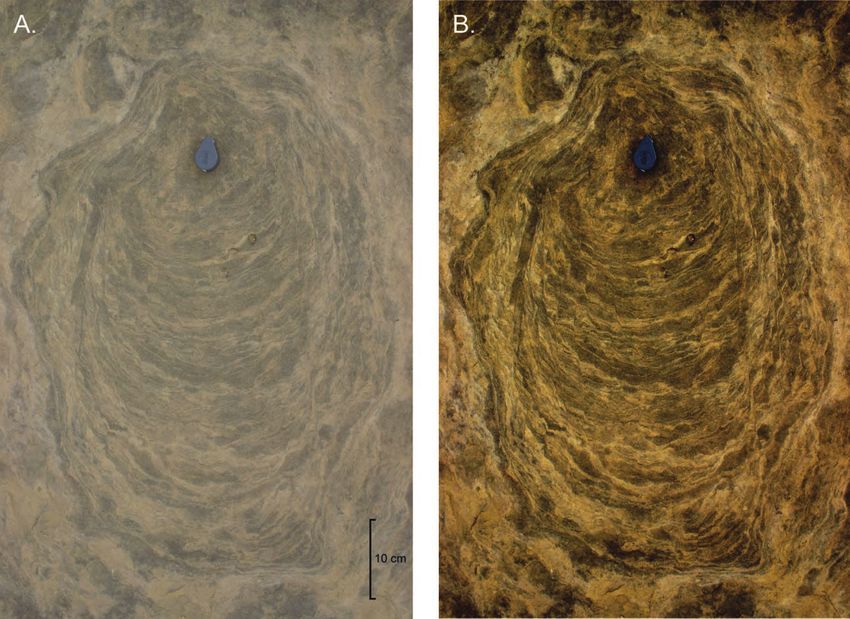
642                                         O . G R AV E R S E N E T A L .

Figure 1. A, Location map. The Twentymile Wash dinosaur track site is located in the southern part of Utah,
southeast of the town of Escalante (37⬚33⬘05⬙N, 111⬚25⬘24⬙W), indicated by a star. Thick solid and dashed lines indicate
roads, while thin dashed line indicates smaller trail and thin solid lines show riverbeds. Shaded areas indicate the
present-day outcrops of the Entrada Sandstone. The front of the straight cliffs is indicated by a thin dotted line. B,
Stratigraphic section of Entrada Sandstone exposed at Twentymile Wash locality. The large dinosaur tracks are found
in the upper laminated part of the section.

load exercised on the different parts of the foot dur-        white to gray, cliff-forming unit along the north-
ing the stride. This is evidenced by sideways-dis-            eastern margin of the Kaiparowits Plateau, at the
placed rims of sediment around and below the im-              Twentymile Wash locality, about 30 km southeast
print of the foot (Milàn et al. 2006).                       of the town of Escalante in southern Utah (fig. 1).
  The first aim of this study is to make a structural         Dinosaur tracks have previously been described
analysis of the faults and joints occurring in the            from the Twentymile Wash locality (e.g., Foster et
sediment around eroded theropod undertracks from              al. 2000; Breithaupt et al. 2004; Milàn and Loope
the Middle Jurassic Entrada Sandstone. The struc-             2007). The majority of the dinosaur footprints
tural analysis will then form the basis for a recon-          found in the Escalante Member are preserved
struction of theropod walking dynamics with spe-              within flat-bedded eolian sand sheets and interbed-
cial emphasis on the timing and shifting of the               ded thin sets of eolian cross-laminated strata that
weight distribution on the feet during the stride.            accumulated above a shallow water table (Loope
                                                              and Simpson 1992). The tracks may have been
                                                              formed during moist, pluvial periods, when the
                      Study Area
                                                              summer monsoon precipitation maintained a high
The footprints analyzed in this study are found in            water table in the dune field (Loope and Rowe
the Escalante Member, in the uppermost part of                2003).
the Middle Jurassic Entrada Sandstone of the San                 The dinosaur ichnofauna at the Twentymile
Rafael Group (Thompson and Stokes 1970). The En-              Wash locality is dominated by theropod footprints
trada Sandstone forms a prominent, 65–68-m-thick,             ranging in length from 15 to 45 cm, but footprints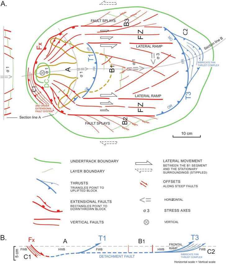
Journal of Geology DINOSAUR TECTONICS 643
as small as 4 cm are occasionally encountered. The
dinosaur tracks of the Entrada-Summerville tran-
sition zone can be traced in various outcrops in
Utah over about 1000 km2 as part of the Moab Me-
gatracksite (Lockley and Hunt 1995; Lockley 1997).
The larger of the theropod footprints that are the
subject of this study, have been assigned to the
ichnogenus Megalosauripus and the smaller foot-
prints to Therangospodus (Foster et al. 2000). In
addition to the abundant footprints of theropods are
two wide-gauge quadrupedal trackways assigned to
the sauropod ichnogenus Brontopodus (Foster et al.
2000).
Footprint Preservation
The dinosaur tracks found at the Twentymile Wash
locality are exposed in a wide range of preserva-
tional styles because of the present-day subaerial
erosion of the sandstone. The tracks are exposed in
a variety of random erosional cuts and as under-
tracks formed on the horizons subjacent to the orig-
inal tracking surface. Many of the theropod tracks
are preserved as true tracks (sensu Lockley 1991).
True tracks reflect the original shape of the dino-
saur’s feet and can, if well preserved, reveal im-
portant details about the soft-part anatomy of the
animal’s feet. When the dinosaurs crossed the
Twentymile Wash site, they not only deformed the
surface but also folded and ruptured the subjacent
layers of sand 20 cm below the track (Milàn and
Loope 2007).
Many of the true tracks at the Twentymile Wash
locality are infilled with darker sediment, which
makes the casts of the footprints stand out in con-
trast with the lighter-colored background (fig. 2A).
As a result of erosion, a majority of the tracks are
preserved only as undertracks. A typical undertrack
morphology at the Twentymile Wash locality is
that of a vaguely defined undertrack, where it is
still possible to identify the imprints of the three
digits and a surrounding zone of deformation
around the remains of the true track (fig. 2B). Where
erosion has proceeded to such an extent that the
true tracks are completely eroded away, a promi-
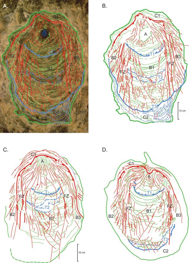
Figure 2. Theropod tracks at the Twentymile Wash lo-
cality exposed in different preservational styles and de- undertrack. Notice the prominent circles of deformation
grees of erosion. A, True track of a large theropod infilled surrounding the undertrack. Knife handle p 10 cm. C,
with sand of a darker color. The shape and outline of the Deep undertracks where the tridactyl shape of the true
track are well defined, with clear impressions from the track is unrecognizable; the only evidence for the former
claws. Scale bar p 10 cm. B, True track here eroded away, presence of the track is the concentric circles developed
with the tridactyl shape only vaguely recognizable in the by erosion of the undertracks. Scale bar p 10 cm.644 O . G R AV E R S E N E T A L .
nent series of oval-shaped deformed layers extends tracking substrate suggests that the sands of the
for 20–30 cm outward from the position of the true Entrada Sandstone had attained an early diagenetic
track (fig. 2C; Milàn and Loope 2007). At this depth patchy consolidation of the near surface layers. In
of erosion, no information about the animal’s foot the description of the deformation of the under-
morphology is obtainable. tracks, we use structural terms in general use
adopted from the regional deformation of the upper
crust (see, e.g., van der Pluijm and Marshak 2004).
Dinosaur Walking Dynamics
The tectonic impact on the theropod undertracks
According to a simplified model of dinosaur walk- is outlined as subvertical planar and curved fault
ing dynamics, the period of contact between the systems separated by low-angle thrust faults (fig.
dinosaur’s foot and the substrate can be divided 4). In addition, minor imbricate fan thrust systems
into three distinct phases (Thulborn and Wade may be encountered at the rear end of the under-
1989; Avanzini 1998). The first phase is the touch- tracks. An impact that resulted in a fold interfer-
down phase, where the foot is moved forward and ence pattern has also been observed.
emplaced onto the sediment surface. This is fol- Structural Units and Associated Structures of the Un-
lowed by the weight-bearing phase, as the body of dertracks. Based on the changing structural char-
the animal passes over the foot that consequently acteristics, the faulted undertracks have been sub-
compresses and deforms the sediment. Last is the divided into three structural units: unit A toward
kickoff phase, when the weight of the animal is the front; unit B at the center, along the sides, and
transferred to the forefoot and the digits as the body rearward; and units C1 and C2 along the front and
moves forward and the foot is pressed backward rear margins of the undertrack (fig. 4). The struc-
during the kickoff and subsequently is lifted and tural units are separated by an extensional fault, Fx
swung toward the next touchdown phase. As evi- (figs. 4, 5), in the front and by low-angle thrust
denced by Gatesy (2001, 2003) and Gatesy et al. faults, T1–T3. Not all the structural units are rep-
(1999), however, the movement phases are more resented in all three of the analyzed undertracks.
complex and represent a continuum of interactions Structural unit A in the central forepart of the
between the foot and the substrate. When viewed undertrack is outlined by a faulted structural de-
from a ground-based reaction force perspective, the pression (fig. 4A, 4B). The depression may be asym-
phases of contact between the animal and the sub- metrical, with the center shifted toward the front
strate can still be divided into three phases, al- of the track (fig. 4C, 4D). The “front” of the de-
though there is a gradual shift between them. At pression is separated from the marginal regime at
the touchdown of the foot, the substrate exercises the front (C1) by an extensional, backward-dipping
a backward and upward force on the animal as it fault (fig. 4). The asymmetrical depressions in par-
decelerates. This shifts to a vertical peak magni- ticular are faulted along steep planar to curved
tude force as the full weight of the animal is applied faults radiating out from the depression center (fig.
to the foot in the weight-bearing phase and shifts 4C, 4D); the backward-directed faults are planar,
to a forward and upward force as the animal reac- while the radiating faults toward the lateral parts
celerates during the kickoff (Roberts and Scales of the depression display an increased curvature.
2002). The identified offsets to the left (looking toward
the front of the footprint) are right-lateral, while
the offsets to the right are left-lateral. To the rear,
Structural Analysis of the Dinosaur Undertracks
the depression is cut out by a backward-directed
Introduction. One of the long theropod track- thrust (T1) dipping toward the front below the de-
ways encountered at the Twentymile Wash locality pression. Unit A is thus lying above the Fx exten-
can be traced for more than 30 m where the surface sional fault in the front as well as the T1 thrust at
has been eroded to such a depth that all of the in- the rear end of the structural depression (fig. 5B).
dividual tracks are exposed as undertracks. Among Structural unit B in the center and toward the
these tracks, three consecutive tracks display ex- rear may be subdivided into three segments. Seg-
tensional and compressional fault systems that are ment B1, in the median part of the undertrack, has
usually associated with tectonic activity of con- subvertical straight faults in two directions inter-
solidated bedrock. The tectonic activity is encoun- secting at an acute angle of ca. 50⬚, forming con-
tered only along a few meters of the dinosaur track- jugate fault systems (fig. 4). The median segment,
way, and the structures are restricted to the B1, is separated from the lateral segments, B2 and
undertracks and do not extend into the surrounding B3, by fault zones (FZ in fig. 5) composed of steep
rock (fig. 3). The brittle deformation of the local faults that parallel the long axis of the undertracks.Journal of Geology DINOSAUR TECTONICS 645 Figure 3. A, Photo of dinosaur undertrack with structural offsets of the thinly laminated sediment package. B, Same as A, with digital manipulation of colors and contrasts to enhance the structural deformation of the undertrack. The lateral segments are identified by splay faults below Fx in structural regime C1 (figs. 4C, 5), while that diverge outward and backward from the par- the imbricate fan at the rear end is developed in allel fault zones along B1. The offsets in the left regime C2 in the footwall block below T3 (figs. 4B, segment (looking toward the front of the footprint) 5). are right-lateral, while the offsets in the right seg- Prototype of Faulted Undertrack in Thin-Bedded ment are left-lateral (figs. 4, 5A). At the rear end, Sandsheet Deposits. The number of structural el- structural unit B may be cut out by a low-angle ements and composite structural systems identi- thrust fault, T3, dipping toward the front below fied in the analyzed undertracks varies from one unit B (fig. 4B, 4D; fig. 5). Additional thrust faults, undertrack to another. However, there is a common T2, may also lie within the B1 segment (fig. 4B, outline of the structural units developed, and most 4C). structural elements are shared by at least two of Structural unit C is encountered between the the three described undertracks. The similarities marginal fault zones, Fx and T3, and the border of between the structural frameworks of the under- the undertrack; the deformation of the undertracks tracks enable the construction of a schematic pro- dies out toward the border in the marginal regime. totype of a faulted undertrack valid for thin-bedded The most conspicuous structures of the border zone sandsheet deposits (fig. 5A). are imbricate fault systems that may occur along In the previous section, the structural units were the front and at the rear end of the undertracks. described as individual composite units. There is, The frontal margin may be cut up into an exten- however, a structural coupling between the units sional fault system developed in the footwall block back through the undertrack. The structural inter-
Journal of Geology                        DINOSAUR TECTONICS                                                      647

relationship is established at structural anomalies          radial faults; this is interpreted as indicating that
encountered along the boundaries between the                 the downward- and backward-directed movement
structural units. In unit A there are lateral overlaps       of unit A outlasted the initial thrusting above a
between the frontal extensional fault (Fx) and the           wider curved ramp with backward transport and
following more narrow intermediate thrust (T1) at            uplift above both the frontal and the oblique seg-
the rear end of unit A (fig. 4). The overlap zones in        ments of the thrust ramp. The interpreted move-
unit A coincide with the front positions of the two          ments along Fx and T1 associated with unit A are
lateral fault zones in unit B. The lateral fault zones       both oriented toward the rear end of the undertrack,
are, to a great extent, restricted to unit B. In one of      and the two bounding faults must belong to a com-
the footprints (fig. 4D), the rear ends of the fault         mon stress regime that linked Fx and T1 together
zones concur with the lateral positions of the tail-         below the structural depression (unit A; fig. 5B).
ing thrust zone (T3; fig. 5A). The parallel fault zones      The T3 thrust plane at the rear end of the under-
may thus form a link from unit A in the front                track is forward concave and is (sub-)parallel with
through unit B and back to unit C2 at the rear end           the boundary of the undertrack at the back. Unit
of the undertrack. The geometrical relationship              B1 sits above the T3 thrust plane in the hanging-
suggests that there may be a dynamic coupling be-            wall block, while the imbricate fan thrust complex
tween the structural units.                                  in unit C2 is developed in the footwall block. The
                                                             offsets in the lateral fault zones and in the subunits
                                                             B2 and B3 indicate a backward thrusting of unit B
                     Kinematic Analysis                      above unit C2 (fig. 5). This is in accordance with
The structural deformation is restricted to the di-          the discordant cutoff of the C2 fan complex in the
nosaur undertracks in an isolated tectonic environ-          footwall block below T3. The thrusting along T1
ment. The undeformed area surrounding each track             and T3 are both toward the back of the undertrack
is thus taken as a stationary reference region rel-          and developed in a backward-directed stress
ative to the deformation identified within the un-           regime.
dertrack. The right-lateral offsets identified in the          The orientation of the stress axes in unit A and
left part of the undertrack (viewed looking toward           subunit B1 can be evaluated from the fault systems
the front) and the left-lateral offsets to the right         in the two units. In unit A, the extensional fault
indicate that there is an overall backward transport         (Fx) at the front and the radial faults within unit A
increasing from the margins of the undertrack and            indicate a downward movement with an initial
toward the median segments (fig. 5A).                        (sub-)vertical maximum stress axis (j1; section line
   The frontal extensional fault (Fx) separates struc-       A in fig. 5). However, the movement along the T1
tural unit A in the hanging-wall block from unit             low-angle thrust fault at the rear end of unit A
C1 in the footwall block; the fault is upward and            points to a stress field with a (sub-)horizontal max-
backward concave and parallels the front border of           imum stress axis (j1) that paralleled the long axis
the undertrack (fig. 5A). As the deformation dies            of the undertrack. The correlation of Fx and T1
out toward the margin of the undertrack in the foot-         below unit A into a common upward-concave fault
wall block (C1), the fault movement between units            system suggests that an original downward-ori-
A and C1 is interpreted as the result of extension           ented maximum stress axis was rotated toward a
and backward movement of unit A, i.e., the hang-             backward-directed maximum stress axis during ro-
ing-wall block (fig. 5B). The T1 thrust at the rear          tation of unit A. In subunit B1, the intersection of
end of unit A is forward and upward concave, and             the steep fault zones of the conjugate fault sys-
unit A also lies above the T1 thrust in the hanging-         tem defines the intermediate stress axis (j2) as a
wall block. The offsets along the radial extensional         (sub-)vertical-oriented axis. The maximum (j1) and
faults in unit A indicate a downward movement                minimum (j3) stress axes are (sub-)horizontal and
toward the median segment (section line A in fig.            bisect the acute and obtuse angles, respectively (fig.
5A). The T1 thrust plane may be offset along the             5A). The fault zones along the lateral boundaries

Figure 4. Three dinosaur tracks showing structural deformation. A, Digitally manipulated photo of undertrack (fig.
3B) with structural interpretation. B, Line drawing of structural interpretation extracted from A. C, D, Line drawings
of structural interpretations of two additional undertracks from the same trackway, also based on manipulated photos
(not shown). See figure 5 for key to symbols and abbreviations.
Figure 5. A, Schematic prototype undertrack based on the structural interpretations of the undertracks in figure 4. The interpreted dimension of the original foot size is shown in orange. A p frontal disk; B1 p median segment; B2, B3 p lateral segments; C1p second-order extensional fault system; C2 p imbricate fan thrust complex; DC p depression center; FR p frontal ramp; Fx p extensional fault; FZ p vertical fault zone; OR p oblique ramp; T1, T3 p thrust faults. B, Cross section interpreted along section line B in A. HWB p hanging-wall block; FWB p footwall block. The dashed gray line indicates the current erosion level.
Journal of Geology                      DINOSAUR TECTONICS                                                  649

of subunit B1 thus parallel the maximum stress axis     axis that parallels the long axis of the rear part of
of the central segment. Subunit B1 is a relatively      the undertrack (fig. 5). There is thus no indication
stable block; no faults within the conjugate fault      of a decelerating touchdown phase with a forward-
system cut across the entire unit. The movement         directed impact of the dinosaur foot at the level of
within the lateral fault zones and the subunits B2      observation (∼10 cm below the original tracking
and B3 along the margins thus took place between        surface). Our description and interpretation of the
the boundaries of the median segment (B1) and the       dynamic phases is based on a two-dimensional se-
stable area surrounding the undertrack (fig. 5A).       quential reconstruction along the center line of the
   The movements of the subunit B1 block (toward        prototype undertrack (figs. 5, 6).
the back of the undertrack) and the associated             1. The starting point for the structural reconstruc-
faults are linked in a composite thrust fault system.   tion is illustrated by the dinosaur foot impact into
In map view, the bounding fault ramp is composed        the ground; the maximum stress axis was vertical
of the combined frontal and oblique ramps estab-        and directed downward (fig. 6A). The maximum ver-
lished along the T3 thrust, while lateral ramps are     tical compression occurred when the full weight of
established along the parallel fault zones (fig. 5A).   the animal was applied to the ground during the
The subunit B1 hanging-wall block is interpreted        weight-bearing phase. The layers below the footprint
as being separated from the stable footwall block       were compressed, and the undertrack formed a
by a detachment fault at the base (fig. 5B). The        structural depression (not illustrated in fig. 6). Ad-
forward movement in the area toward the back of         ditional sideways pressure caused the formation of
the undertrack of the imbricate fan (C2) in front of    a raised rim of displaced material around the foot.
T3 adds naturally to the B1 thrust complex in the          2. The early deformation of the undertrack formed
vaning deformation front along the rear margin of       in phase 1 formed a composite disk comprising
the undertrack. In the opposite direction, the B1       structural unit A (figs. 5, 6B). The disk developed as
thrust fault system can be extended back against        a hanging-wall block that rotated above a curved
the movement direction into unit A situated in the      fault. The fault surface is composed of the exten-
hanging-wall block above T1 at the rear end of the      sional fault (Fx) at the front and the thrust fault (T1)
B1 block (relative to the movement direction of the     at the rear end of unit A. The rotation and backward
thrust fault system; fig. 5). The T1 thrust acted as    movement of the disk was associated with rotation
a combined frontal and oblique ramp relative to         of the principal stress axes; the vertical stress com-
unit A, while the “lateral” ramps may be outlined       ponent was reduced while a backward-directed
by the bounding radial faults converging toward the     stress component started to grow (fig. 6B). The initial
depression center. The movement of the combined         disk rotation followed the weight-bearing phase (1);
thrust fault system outlined by units A-B1-C2 can       the weight of the dinosaur was gradually transferred
thus be traced back to a punctiform force situated      from the rear part of the foot toward the front end
at the depression center in unit A (fig. 5).            of the digits during the early kickoff phase. The met-
                                                        atarsal pad was lifted clear of the ground during this
                                                        stage (2) as the tips of the digits were forced down-
               Dynamic Interpretation
                                                        ward. The shift in weight distribution formed a ro-
Based on the structural and kinematic analyses and      tational disk that cut through to the original ground
the reconstructed prototype of a faulted undertrack,    surface behind the foot.
it is possible to establish three phases of defor-         3. During the intermediate and late kickoff phase,
mation related to the dinosaur foot movement. The       deformation extended backward, as evidenced by the
identified deformation phases were governed by          development of new thrust ramps, i.e., an inter-
significant shifts in the dinosaur weight distribu-     mediate ramp T2 (figs. 4A–4C, 6C), and/or the T3
tion exercised on each foot during the stride. We       thrust ramp at the rear end of the undertrack (fig.
have integrated a sequential reconstruction of the      4A, 4B, 4D; fig. 6D). The backward extension of the
structural deformation sequence with an interpre-       deformation accompanied a growing horizontal
tation of the dinosaur foot impact and the changing     stress component at the expense of the vertical stress
ground contact associated with the stacked defor-       component. This indicates a continued rotation of
mation phases (fig. 6). Both the extensional fault      the principal stress axes exerted by the dinosaur foot
(Fx) and the compressional thrust faults (T1–T3)        at the frontal disk. The continued rotation of the
indicate a backward movement of the mapped              front disk is interpreted as being governed by the
units. The deformation is associated with an ini-       ongoing rotation of the dinosaur foot during perfor-
tially vertical maximum stress axis at the front of     mance of the kickoff phase. Along with the rotation,
the undertrack and a horizontal maximum stress          the rear part of the dinosaur foot was lifted off the
Figure 6. Structural interpretation of the dynamic evolution of dinosaur foot impact during the weight-bearing and kickoff phases. A, Dinosaur footprint and rim deformation established during the peak weight-bearing phase. B, Formation of the frontal disk (A) during the initial kickoff phase. C, Continued rotation and forward movement of the dinosaur foot contact during the intermediate kickoff phase lead to a growing backward-directed movement vector and the evolution of an imbricate fan thrust system. D, During the late kickoff phase, the increased horizontal vector was responsible for the continued backward extension of the fold-thrust system that faded out at the sole in the second-order imbricate fan at the back.
Journal of Geology                       DINOSAUR TECTONICS                                                651

ground, and the backward-directed power of the foot       acteristics of the substrate and the presence of
was further concentrated on the digits (fig. 6C, 6D).     structural markers, e.g., laminations. The size of
   The lateral overlap between the broad frontal ex-      the structures associated with the undertracks may
tensional fault (Fx) and the more narrow thrust           be compared to laboratory experiments performed
fault (T1) at the rear end of the frontal disk (fig. 5)   during sandbox analogue models of fault-related
shows that the backward-directed power was con-           folding (Storti et al. 1997).
centrated toward the center during the rotation of           The development of the undertrack structures
the disk. This interpretation is further supported        analyzed in this article requires special strength
by the normal faulting and offset of the thrust ramp      and competency conditions that are usually not en-
(T1) along the radiating faults, as illustrated by the    countered in unconsolidated sediments close to the
map of the undertrack and the cross section along         earth’s surface. The yield strength of unconsoli-
line A (fig. 5). The structural evolution shows that      dated, grain-supported clastic sediments is close to
the backward-directed force of the dinosaur was           zero at the earth’s surface, and this may be the
transferred to the middle digit during the late kick-     reason why undertrack structures similar to the
off phase. Furthermore, the structures suggest that       structures analyzed in this article have not been
the lateral digits did not move toward the middle         described before. In order for us to establish the
digit; if this had been the case, the lateral digits      strength and competency necessary for the devel-
would have left a transverse impact structure in-         opment of the observed structures, the sands of the
terfering with the radial faults extending from the       Entrada Sandstone locally must have attained an
frontal depression center, and this did not happen        early diagenetic consolidation of the near surface
(figs. 4, 5).                                             layers. This may have been accomplished by early,
   The backward translation of the force from the         near-surface cementation, driven by evaporation
frontal disk was transferred along the two lateral        during the dry season under a subtropical, monsoon
fault zones combined with a basal detachment fault        climate (Loope and Rowe 2003).
(fig. 5). The similar widths of the frontal exten-           In the trace fossils encountered today, it is not
sional fault (Fx) and the thrust fault to the rear (T3)   possible to measure the rheological properties of
correlate with the outer margins of the lateral fault     the substrate during dinosaur track making. Fur-
zones (figs. 4, 5). This may indicate that the initial    thermore, rheological properties also depend on the
backward movement took place across a defor-              strain rate, i.e., the elongation per unit time. The
mation zone that was governed by the width of the         duration of the isolated tectonic microcosm created
dinosaur foot during the maximum weight-bearing           during each dinosaur step lasted only a few seconds.
phase. The subsequent narrowing of the backward           Even compared to the small size of the analyzed
translation force during the kickoff phase estab-         structures, the growth and release of the estab-
lished above may also be inferred from the in-            lished stress were extremely rapid. The strain rates
creased movement across the lateral fault zones to-       of the structures developed in the undertracks were
ward the median segment (B1) because the width            several orders higher than the strain rates encoun-
of the median segment correlates with the width           tered during orogenic deformation in a plate tec-
of the T1 thrust fault (figs. 4, 5).                      tonic setting in the earth’s crust. The high strain
                                                          rate established during each dinosaur step may thus
                                                          have increased the relative competence of the walk-
                     Discussion
                                                          ing substrate. Based on the contemporaneous de-
  Structural Deformation Sequence of Undertracks.         velopment of faults and folds in the fold-thrust
The structural deformation analysis of the dinosaur       structures of the undertracks, it is estimated that
undertracks has revealed a set of minor-scale struc-      the rheological conditions illustrate a system close
tures that are analogous to crustal-scale orogenic        to the brittle-ductile transition at the time of
structures usually associated with plate tectonics.       deformation.
The thrust ramp systems mapped from the dino-                Tracking and Disk Formation.      The well-devel-
saur undertracks mimic fold-thrust structures from        oped disks, bound by thrust ramps described from
foreland belts known from the Canadian Rocky              this study, are the result of an initial powerful
Mountains and the Appalachians. The deformation           downward movement of the foot, followed by an
is restricted to individual undertracks, and each di-     almost entirely backward-directed movement. The
nosaur step developed its own tectonic microcosm          tracks were emplaced on a horizontal surface, and
during the contact with the substrate. The devel-         the backward-directed deformations resulted from
opment of recognizable structures during the di-          the powerful backward foot movements during the
nosaur stride depended on the rheological char-           stride. Disks of displaced sediment associated with
652 O . G R AV E R S E N E T A L . Figure 7. Trackway from a large reptile walking up the slope front of a paleodune in the Permian Coconino Sandstone of Grand Canyon exposed along the Hermit Trail at the South Rim of Grand Canyon. A, Trackway consisting of paired manus-pes imprints and a sinusoidal tail drag mark. Rectangle indicates location of close-up shown in B and C. B, Close-up photo of manus and pes couple, where large disks of displaced material are evident on the tracking surface behind the tracks. C, Interpretative drawing of the structures evident on the tracking surface. The disk is composed of a number of faults, most prominently developed on the outside of the trackway. The shaded area indicates the total area of sediments disturbed by the foot. tracks of dinosaurs and other vertebrates have hith- coming). Permian reptile tracks from the eolian Co- erto received little attention in vertebrate ichnol- conino sandstone exposed along the Hermit Trail ogy. However, a few studies describe similar struc- at the South Rim of Grand Canyon further show tures, most of them from tracks and trackways in large disks of displaced material behind each foot- eolian settings (Lockley 1991). Such disks of dis- print in a trackway progressing up the slope front placed sediment are especially abundant in the nu- of a paleodune (McKee 1944; fig. 7). merous reptilian tracks and trackways from the Co- The formation of the disks described in the ex- conino Sandstone of Grand Canyon (McKee 1944), amples above is not directly comparable to that of and Pleistocene tracks and trackways from now ex- the disks described from the dinosaur tracks in this tinct goats from Mallorca walking up the slopes of article. The identification of backward force exer- ancient eolianites have preserved similar struc- cised on the tracking substrate by the Permian rep- tures. These tracks have preserved well-developed tiles (McKee 1944), the humans and animals from disks of displaced sediment on the downslope side Rhodes (Bromley et al., forthcoming; Milàn et al., of the tracks (Fornós et al. 2002). A similar disk of forthcoming), and the Pleistocene goats (Fornós et displaced material is reported from the downslope al. 2002) was supported by the fact that these an- side of a hoof imprint in a Quaternary eolianite imals were walking on sloping surfaces, so that the from the Greek island of Rhodes (Milàn et al., forth- impact angle of the foot exercised a stronger force coming). Indirect evidence of disk formation in con- onto the substrate, thus enhancing the formation nection with tracks comes from eroded undertracks of displaced disks behind the animals. This is in of humans and cattle in Roman-age beach rock contrast to the tracks of this article, which were from Rhodes, where the different grain sizes of the emplaced on a horizontal surface, and which can beach rock are arranged in semilunate units on the only be the result of a powerful backward com- downslope side of the tracks (Bromley et al., forth- ponent of the foot movement during the stride.
Journal of Geology                          DINOSAUR TECTONICS                                                     653

  Reconstruction of Walking Dynamics. Even though             that the initial imprint and associated undertracks
the true tracks are eroded away, based on the struc-          of the anterior end of the foot, which reflect a down-
tural and kinematic analyses of the undertracks               ward movement, was subsequently deformed by
from the Twentymile Wash locality, it is possible to          the posterior movements of the sediment caused
establish the walking dynamics of the actual dino-            by the foot itself.
saur responsible for the studied (under-)trackway.
This study thereby differs from previous reconstruc-
                                                                                   Conclusions
tions of dinosaur walking dynamics that were based
on footprints; the previous analyses used the direct          Deformed dinosaur undertracks from the Entrada
deformation of the true track to reconstruct the foot         Sandstone exhibit a complex set of local thrust
movements during the stride.                                  ramp systems created in isolated tectonic systems
   The complex system of displaced disks from the             during contact of dinosaur feet with the ground.
tracks in this study reveals information about the            The small-scale, dinosaur-induced thrust ramp sys-
end of the weight-bearing phase and the kickoff               tems are similar to crustal-scale tectonics encoun-
phase, while no remains of deformation from the               tered in orogenic foreland basins.
touchdown phase are present at this level of ero-                During dinosaur track making, a rotated disk was
sion. Based on the described deformations, the fol-           created below the dinosaur foot during the transi-
lowing reconstruction of the walking dynamics can             tion from the weight-bearing phase to the kickoff.
be established. During the end of the weight-bear-            Subsequently, during the kickoff phase, the disk
ing phase, the weight of the dinosaur was trans-              was forced backward during the creation of the im-
ferred toward the distal anterior parts of the foot,          bricate fold-thrust system.
which then became more deeply imprinted into the                 The deformation of the tracking surface suggests
sediment (fig. 6B), as was almost always the case             that the Entrada Sandstone locally had attained an
with tridactyl theropod dinosaurs. As the body of             early diagenetic consolidation, facilitating the de-
the animal moved forward in the initial part of the           velopment of the brittle-ductile structures. The tec-
kickoff, the weight was lifted clear of the rear end          tonic deformation induced by the dinosaur’s foot
of the foot and the weight of the animal became               created a disturbed zone of up to three times the
concentrated on the digits. As the dinosaur accel-            length of the dinosaur foot. The incorporation of
erated forward in the kickoff, the foot was forced            structural analysis into ichnological work has
backward, with all the weight concentrated on the             proven to be useful in the reconstruction and un-
distal ends of the digits (fig. 6C, 6D). This implies         derstanding of dinosaur track making.

                                               REFERENCES CITED

Allen, J. R. L. 1989. Fossil vertebrate tracks and indenter     Pleistocene aeolianites from Mallorca (Balearic Is-
   mechanics. J. Geol. Soc. Lond. 146:600–602.                  lands, western Mediterranean). Palaeogeogr. Palaeo-
———. 1997. Subfossil mammalian tracks (Flandrian) in            climatol. Palaeoecol. 180:277–313.
   the Severn Estuary, S.W. Britain: mechanics of for-        Foster, J. R.; Hamblin, A. H.; and Lockley, M. G. 2000.
   mation, preservation and distribution. Philos. Trans.        The oldest evidence of a sauropod dinosaur in the
   R. Soc. B 352:481–518.                                       western United States and other important vertebrate
Avanzini, M. 1998. Anatomy of a footprint: bioturbation         trackways from Grand Staircase–Escalante National
   as a key to understanding dinosaur walk dynamics.            Monument, Utah. Ichnos 7:169–181.
   Ichnos 6:129–139.                                          Gatesy, S. M. 2001. Skin impressions of Triassic thero-
Breithaupt, B. H.; Matthews, N. A.; and Noble, T. A.            pods as records of foot movements. Bull. Mus. Comp.
   2004. An integrated approach to three-dimensional            Zool. 156:137–149.
   data collection at dinosaur tracksites in the Rocky        ———. 2003. Direct and indirect track features: what
   Mountain West. Ichnos 11:11–26.                              sediment did a dinosaur touch? Ichnos 10:91–98.
Bromley, R. G.; Uchman, A.; Milàn, J; and Hansen, K. S.      Gatesy, S. M.; Middleton, K. M.; Jenkins, F. A., Jr.; and
   Forthcoming. Rheotactic Macaronichnus, and human             Shubin, N. H. 1999. Three-dimensional preservation
   and cattle trackways in Holocene beachrock, Greece:          of foot movements in Triassic theropod dinosaurs. Na-
   reconstruction of palaeoshoreline orientation. Ichnos.       ture 399:141–144.
Brown, T., Jr. 1999. The science and art of tracking. New     Lockley, M., and Hunt, A. P. 1995. Dinosaur tracks and
   York, Berkley, 219 p.                                        other fossil footprints of the western United States.
Fornós, J. J.; Bromley, R. G.; Clemmensen, L. B; and Rod-      New York, Columbia University Press, 338 p.
   riguez-Perea, A. 2002. Tracks and trackways of My-         Lockley, M. G. 1991. Tracking dinosaurs. New York,
   otragus balearicus Bate (Artiodactyla, Caprinae) in          Cambridge University Press, 238 p.
654 O . G R AV E R S E N E T A L . ———. 1997. The paleoecological and paleoenvironmen- a Quaternary eolian oolite from Rhodes, Greece. In tal utility of dinosaur tracks. In Farlow, J. O., and Bromley, R. G.; Buatois, L. A.; Márango, M. G.; Genise, Brett-Surman, M. K., eds. The complete dinosaur. J. F.; and Melchor, R. N., eds. Sediment-organism in- Bloomington, Indiana University Press, p. 554–578. teractions: a multifaceted ichnology. SEPM Spec. Loope, D. B., and Rowe, C. M. 2003. Long-lived pluvial Publ. episodes during deposition of the Navajo Sandstone. Milàn, J.; Clemmensen, L. B.; and Bonde, N. 2004. Ver- J. Geol. 111:223–232. tical sections through dinosaur tracks (Late Triassic Loope, D. B., and Simpson, E. L. 1992. Significance of lake deposits, East Greenland): undertracks and other thin sets of eolian cross-strata. J. Sediment. Res. 62: subsurface deformation structures revealed. Lethaia 849–859 37:285–296. Manning, P. 2004. A new approach to the analysis and Milàn, J., and Loope, D. B. 2007. Preservation and erosion interpretation of tracks: examples from the dinosau- of theropod tracks in eolian deposits: examples from ria. In McIlroy, D., ed. The application of ichnology the Middle Jurassic Entrada Sandstone, Utah, U.S.A. to palaeoenviromental and stratigraphic analysis. J. Geol. 115:375–386. Geol. Soc. Lond. Spec. Publ. 228:93–123. Roberts, T. J., and Scales, J. A. 2002. Mechanical power McKee, E. D. 1944. Tracks that go uphill. Plateau 16:61– output during running accelerations in wild turkeys. 72. J. Exp. Biol. 205:1485–1494. Milàn, J.; Avanzini, M.; Clemmensen, L. B.; Garcia-Ramos, Storti, F.; Salvini, F.; and McClay, K. 1997. Fault-related J. C.; and Piñuela, L. 2006. Theropod foot movement folding in sandbox analogue models of thrust wedges. recorded from Late Triassic, Early Jurassic and Late Ju- J. Struct. Geol. 19:583–602. rassic fossil footprints. In Harris, J. D.; Lucas, S. G.; Thompson, A. E., and Stokes, W. L. 1970. Stratigraphy Spielmann, J. A.; Lockley, M. G.; Milner, A. R. C.; and of the San Rafael Group, southwest and south central Kirkland, J. I., eds. The Triassic-Jurassic terrestrial tran- Utah. Utah Geol. Mineral. Surv. Bull. 87:1–53. sition. N. M. Mus. Nat. Hist. Sci. Bull. 37:352–364. Thulborn, R. A., and Wade, M. 1989. A footprint as his- Milàn, J., and Bromley, R. G. 2006. True tracks, under- tory of movement. In Gillette, D. D., and Lockley, M. tracks and eroded tracks, experimental work with tet- G., eds. Dinosaur tracks and traces. New York, Cam- rapod tracks in laboratory and field. Palaeogeogr. Pa- bridge University Press, p. 51–56. laeoclimatol. Palaeoecol. 231:253–264. van der Pluijm, B. A., and Marshak, S. 2004. Earth struc- Milàn, J.; Bromley, R. G.; Titschack, J.; and Theodorou, ture: an introduction to structural geology and tec- G. Forthcoming. A diverse vertebrate ichnofauna from tonics. New York, Norton, 656 p.
You can also read