Airborne polarimetric Doppler weather radar: trade-offs between various engineering specifications - Geoscientific ...
←
→
Page content transcription
If your browser does not render page correctly, please read the page content below
Geosci. Instrum. Method. Data Syst., 7, 21–37, 2018
https://doi.org/10.5194/gi-7-21-2018
© Author(s) 2018. This work is distributed under
the Creative Commons Attribution 4.0 License.

Airborne polarimetric Doppler weather radar: trade-offs between
various engineering specifications
Jothiram Vivekanandan and Eric Loew
National Center for Atmospheric Research (NCAR), Boulder, CO, USA

Correspondence: Jothiram Vivekanandan (vivek@ucar.edu)

Received: 10 August 2017 – Discussion started: 6 September 2017
Revised: 18 December 2017 – Accepted: 19 December 2017 – Published: 30 January 2018

Abstract. NCAR EOL is investigating potential configura-           1   Introduction
tions for the next-generation airborne phased array radar
(APAR) that is capable of retrieving dynamic and microphys-        Characterizing location, intensity, and motion of hurricanes,
ical characteristics of clouds and precipitation. The APAR         tornados, and extreme precipitation events and understand-
will operate at C band. The APAR will use the electronic           ing effects of clouds and aerosols on the earth radiation bud-
scanning (e-scan) feature to acquire the optimal number of         get requires a better understanding of the kinematic (storm
independent samples for recording research-quality measure-        motion and structure) and microphysical processes (particle
ments. Since the airborne radar has only a limited time for        growth, phase changes) within these storms. This remains
collecting measurements over a specified region (moving air-       a challenge for both the scientific and operational commu-
craft platform ∼ 100 m s−1 ), beam multiplexing will signifi-      nities. Observing these events is challenging using ground-
cantly enhance its ability to collect high-resolution, research-   based radars as the conditions that lead to high-impact events
quality measurements. Beam multiplexing reduces errors in          typically occur in remote areas (e.g., hurricanes over the
radar measurements while providing rapid updates of scan           ocean, orographic precipitation in rugged terrain) or because
volumes. Beamwidth depends on the size of the antenna              of large uncertainties on the timing and location (e.g., tor-
aperture. Beamwidth and directivity of elliptical, circular,       nado, extreme precipitation events) related to suboptimal
and rectangular antenna apertures are compared and radar           radar coverage. Airborne radar is a powerful tool to observe
sensitivity is evaluated for various polarimetric configura-       weather systems, in particular, storms over complex terrain,
tions and transmit–receive (T/R) elements. In the case of          the ocean, polar regions, and forest regions not easily ob-
polarimetric measurements, alternate transmit with alternate       servable by ground-based radars (Bluestein and Wakimoto,
receive (single-channel receiver) and simultaneous reception       2003). A scanning Doppler radar on an airborne platform
(dual-channel receiver) is compared. From an overall archi-        is used for estimating dual-Doppler winds with the help of
tecture perspective, element-level digitization of T/R module      rapid scanning as the aircraft flies past a storm (Hildebrand
versus digital sub-array is considered with regard to flexibil-    et al., 1996). Scanning Doppler radar with dual-polarization
ity in adaptive beamforming, polarimetric performance, cali-       capability on an airborne platform is capable of measuring
bration, and data quality. Methodologies for calibration of the    dual-Doppler winds and retrieving particle types (ice or wa-
radar and removing bias in polarimetric measurements are           ter) and shapes and liquid–ice water contents using reflectiv-
outlined. The above-mentioned engineering options are eval-        ity (Z), differential reflectivity (ZDR ), specific propagation
uated for realizing an optimal APAR system suitable for mea-       phase (KDP ), and linear depolarization ratio (LDR).
suring the high temporal and spatial resolutions of Doppler           At present, no other instrument other than an airborne po-
and polarimetric measurements of precipitation and clouds.         larimetric Doppler phased array radar (APAR) system has the
                                                                   potential to estimate high temporal and spatial measurements
                                                                   of 3-D winds and microphysics concurrently (Vivekanandan
                                                                   et al., 2014). NCAR’s Earth Observing Laboratory (EOL) is
                                                                   currently conducting a design study for a future APAR.

Published by Copernicus Publications on behalf of the European Geosciences Union.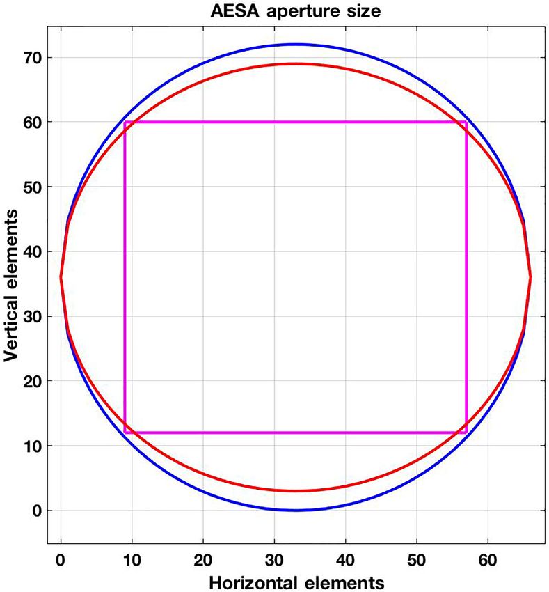
22                                            J. Vivekanandan and E. Loew: Airborne polarimetric Doppler weather radar

   Between 1992 and 2013 NCAR operated the research-
quality Doppler radar, ELDORA/ASTRAIA (Electra
Doppler Radar/Analyese Steroscopic par Impulsions Aero-
porte, hereafter referred as ELDORA). The ELDORA was
configured with dual-slotted waveguide array antennas using
a dual-transmitter, dual-beam, rapid-scan, and step-chirped
waveform (Girardin-Gondeau et al., 1991) that significantly
improved the along-track spatial resolution from 750 to
300 m when compared to NOAA’s airborne tail Doppler
radar (TDR) (Hildebrand et al., 1996). The ELDORA was
jointly developed by NCAR and the Centre d’Étude des
Environments Terrestre et Planétaires (CETP), France.
In recent years, CETP became LATMOS (Laboratoire
Atmospheres, Milieux, Observations Spatiales). It collects
research-quality Doppler and reflectivity measurements that         Figure 1. Notional schematic of APAR’s four AESA antenna panel
continue to set the standard for airborne radar; however,           placements on the C-130. There are two side panels on port and
ELDORA X-band radar’s penetration into precipitation                starboard of the fuselage, third panel on the top, and the fourth panel
is limited by attenuation and it is not designed to collect         at the rear ramp.
polarimetric measurements to remotely estimate micro-
physics. ELDORA has been placed in dormancy because its
airborne platform (Naval Research Lab P-3 587) was retired          5900 kg. NCAR EOL/RAF maintains the NSF/NCAR C-130
in January 2013. The US research community has strongly             aircraft in its fleet for airborne atmospheric measurements,
voiced the need to continue measurement capability similar          including dropsonde, in situ sampling, and remote sensing of
to that provided by ELDORA (Smith et al., 2012).                    clouds, chemistry, and aerosols.
   The combination of remote and in situ sensors on a sin-             This paper is organized as follows. Section 2 describes
gle airborne platform will serve the observational needs            radar system and its major subsystems. Rationale for se-
for broader scientific communities of cloud microphysics,           lection of transmit frequency is presented in Sect. 3. Dis-
mesoscale meteorology, atmospheric chemistry, and climate,          cussions related to polarimetric configurations and advan-
and it will fill a critical gap in the current airborne observing   tage of agile beam scanning are presented in Sects. 4 and 5.
facilities. An APAR deployed on aircraft with long on-station       Various antenna aperture configurations and corresponding
time, such as the C-130, will allow investigation of weather        beamwidth characteristics are presented in Sect. 6. The sen-
systems such as monsoons, tropical cyclones, severe con-            sitivity of the radar measurements depends on transmit and
vection over continents, orographic precipitation, convection       receive hardware characteristics, polarimetric measurement
over the oceans, and polar and low to middle atmospheric            configuration, and signal processing. Expected radar sensi-
chemistry. A schematic of the APAR antenna panels on the            tivity as a function of a few key parameters is discussed in
C-130 is shown in Fig. 1. APAR will feature four remov-             Sect. 7. PAR with digital architecture is amenable for con-
able C-band active electronically scanned arrays (AESAs)            sistently maintaining data quality, deployment of radar with
mounted on top, both sides, and the bottom of the aircraft.         repeatable and robust calibration, and formation of fan-beam
Each antenna will have dual-Doppler and polarimetric capa-          and pencil-beam configuration for imaging rapidly chang-
bilities. This configuration, when integrated with data from        ing weather system. In this regard possible analog and digi-
the NSF/NCAR C-130 nose radar, will provide 360◦ hori-              tal beamforming architecture configurations are compared in
zontal surveillance radar scan coverage and volumetric data         Sect. 8. A brief description of calibration requirement is dis-
collection. Radar products can be displayed in real time. The       cussed in Sect. 9. Estimates of biases in radar measurements
AESA placement provides for flexible scanning capabilities          as a result of cross coupling in polarimetric mode is shown
for 3-D data volume generation.                                     in Sect. 10. Section 11 presents a summary.
   The real-time radar displays on the aircraft provide sit-
uational awareness to aircraft pilots allowing for safe air-
craft operations in the vicinity of extreme weather. The 3-D        2   System description
volume-scan data not only can help guide the NSF/NCAR
C-130 research in and around weather of interest but also has       Preliminary design specifications of peak power, beamwidth,
the potential to be used to guide other aircraft conducting         dual-polarimetric configuration, scan timing sequences, and
research in the vicinity. The C-130 is a versatile and capa-        signal processing are outlined in Vivekanandan et al. (2014);
ble research platform that carries a wide variety of scientific     some key technical specifications are presented in Table 1.
payloads. The C-130 has a 10 h flight endurance, a 5400 km          The APAR will operate at C band. It will use the e-scan fea-
range at up to 8.2 km altitude, and a payload capacity of up to     ture to acquire the optimal number of independent samples

Geosci. Instrum. Method. Data Syst., 7, 21–37, 2018                     www.geosci-instrum-method-data-syst.net/7/21/2018/
J. Vivekanandan and E. Loew: Airborne polarimetric Doppler weather radar                                                              23

Table 1. Technical specifications of C-band APAR.

      Parameter                                                          Numeric value
      Operating frequency                                                C band: 5.35–5.45 GHz (FAA requirement)
      Antenna aperture                                                   1.9 m major and 1.8 m minor diameter ellipse.
      Maximum full panel thickness (radome + antenna + T/R mod-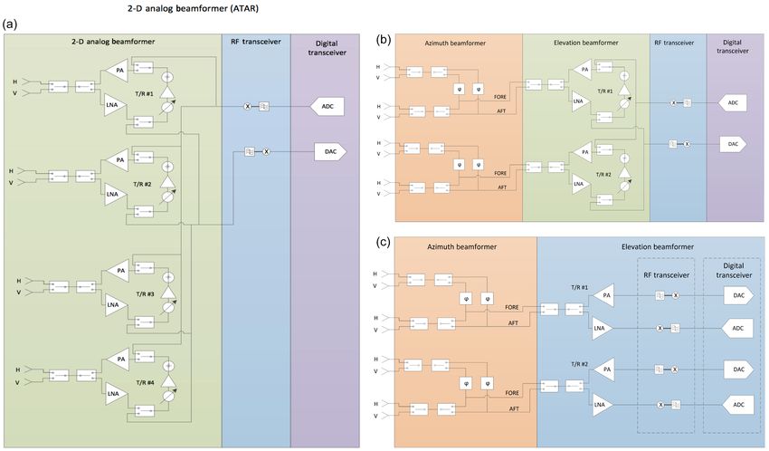
24                                             J. Vivekanandan and E. Loew: Airborne polarimetric Doppler weather radar

Figure 2. Simplified block diagram of PAR. It consists of six components: (1) array antenna front end, (2) T/R modules, (3) array antenna
backplane, (4) radar back end, (5) radar processor and display, and (6) radar scheduler.

ferent frequencies must be transmitted each pulse repetition           nents in the T/R module due to its self-heating. Heat sinks are
time. This is necessary to have sufficient independent sam-            placed outward into the space between the antenna aperture
ples to reduce reflectivity and velocity variances while still         and backplane printed circuit boards. Cooling can be accom-
achieving the desired along-track resolution.                          plished via forced air convection or a liquid cooling via a
   The T/R module consists of a matrix of individual T/R               cold plate. The LNA determines the noise figure of the re-
modules. It is a multi-layer printed circuit board that includes       ceive chain and it is placed closest to the receive port of the
monolithic microwave integrated circuit (MMIC) compo-                  antenna. Each T/R element is coupled to a two-port radiator
nents, namely, digital phase shifters, attenuators, a PA, low          for dual-polarization transmission and reception. An FPGA
noise amplifier (LNA), various drive amplifiers, high-speed            controls the attenuator, phase shifter, and switches for the de-
field effect transistor switches, and a field programmable             sired performance of APAR.
gate array (FPGA). The digital 6-bit phase shifter supplies               The radar back end includes master FPGAs for commu-
the necessary phase to the RF signal for steering the beam             nicating scan angle, polarization, and pulse information to
in a specified direction. The digital attenuator tapers trans-         the FPGAs in each line replaceable unit from the radar
mit and receive amplitudes across the active aperture for re-          scheduler. The radar back end consists of up and down
ducing antenna sidelobes and also for aligning the ampli-              converters between intermediate frequency and RF, digi-
tudes of each T/R element. Transmit and receive amplitudes             tal transceivers, and a host computer for generating radar
are tapered across the aperture to lower sidelobes. Various            measurements including mean velocity, spectrum width, and
aperture-tapering options are presented in Sect. 7.                    dual-polarimetric observables and associated displays for all
   The high-power amplifier (HPA) amplifies the RF trans-              generated parameters.
mit signal and is capable of handling short and long pulses.
It dissipates a significant amount of power and the heat gen-
erated must be removed for safe operation of the T/R module.
The HPA has the shortest lifetime among all of the compo-

Geosci. Instrum. Method. Data Syst., 7, 21–37, 2018                        www.geosci-instrum-method-data-syst.net/7/21/2018/
J. Vivekanandan and E. Loew: Airborne polarimetric Doppler weather radar                                                               25

Figure 3. Panels (a, b, c) indicate the reflectivity without attenuation simulated from DSD for S-, C-, and X-band polarimetric radar,
respectively, on 17 September 1998, 22:11 UTC. Panels (d, e, f) indicate the measured reflectivity with attenuation effect for S-, C-, and
X-band polarimetric radar, respectively. The radar is located in the center of each panel.

3   Transmit frequency                                                 power and antenna and receiver gain factors, it is more com-
                                                                       monly used for attenuation correction.
                                                                          In order to characterize the effect of attenuation on S-, C-,
X-band and shorter wavelengths are preferred choices for               and X-band polarimetric radar measurements, intrinsic ZHH
mobile ground-based and airborne deployments because the               and attenuated ZHH were simulated for a rain event. The rain
radar antenna is much smaller in size than the S-band or               medium is characterized by a drop size distribution (DSD).
C-band antennas for a specified beam width. The larger                 Polarimetric radar measurements at S band are used for es-
backscatter cross section of particle sizes smaller than the           timating DSD (Brandes et al., 2004). The data used in this
wavelength (Rayleigh scattering) significantly improves the            study were collected in east-central Florida during the sum-
detection limit (Lhermitte, 1987; Clothiaux et al., 1995). In          mer of 1998 in a special experiment. For the retrieved DSDs,
the Rayleigh scattering regime, the radar cross section at X           ZHH and attenuated ZHH in S-, C-, and X-band polarimet-
band is 10 and 20 dB larger than at C band and S band, re-             ric were simulated using rigorous electromagnetic scattering
spectively. For a specified transmit power and antenna gain,           cross sections (Vivekanandan et al., 2004).
X-band radar is also more sensitive to detecting lighter pre-             Intrinsic reflectivities without considering the attenuation
cipitation than S- or C-band radar. However, a major disad-            effect were almost similar in S, C, and X as shown in Fig. 3a,
vantage of the X-band radar signal is that it is more suscepti-        b, and c except there are subtle differences due to Mie scatter-
ble to attenuation than an S-band and C-band radar signal.             ing at C and X bands. However, effects of attenuation on re-
The intervening precipitation between radar and measure-               flectivity are noticeable in Fig. 3e and f. In the regions south
ment volume causes attenuation. The amount of attenuation              of the radar, X-band reflectivity is severely attenuated and the
is proportional to the intensity of precipitation. Horizontal          precipitation is not detected. In comparison with X band, the
X-band co-polarization reflectivity (ZHH ) and ZDR are usu-            C-band reflectivity is weakly attenuated. In this example, the
ally underestimated due to attenuation of the radar signal as          convection system produced about 0.04, 0.4, and 2 dB km−1
it propagates through precipitation. Attenuation in precipita-         of attenuation at S, C, and X bands, respectively. The max-
tion at X band is about a factor of 5 to 7 times larger when           imum total accumulated attenuation could reach about 1.2,
compared to C band (Bringi and Chandrasekar, 2001). In the             10, and 30 dB for S, C, and X band, respectively. X-band
case of rain, KDP is proportional to rain intensity. Attenuation       radar is subjected to the most significant attenuation in pre-
and specific differential attenuation are almost linearly pro-         cipitation systems and the S-band radar has the least atten-
portional to KDP (Bringi et al., 1990). As KDP is unaffected
by attenuation radar system bias due to change in transmit

www.geosci-instrum-method-data-syst.net/7/21/2018/                           Geosci. Instrum. Method. Data Syst., 7, 21–37, 2018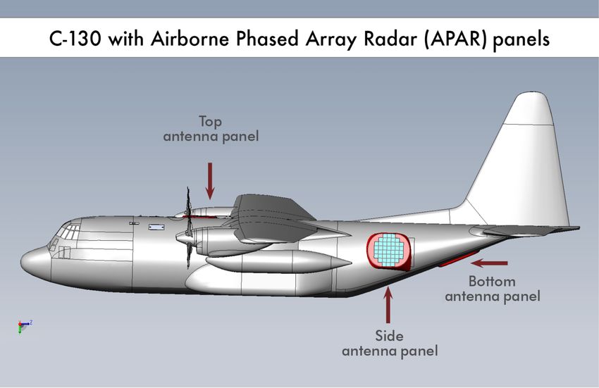
26                                           J. Vivekanandan and E. Loew: Airborne polarimetric Doppler weather radar

Figure 4. Illustration of contiguous and beam multiplexing pairs
(Curtis, 2009).

uation. The C-band radar signals experience less attenuation       Figure 5. Elliptical, circular, and square phased array antenna aper-
when compared to X-band radar signals.                             tures.
   However, attenuated C-band radar measurements must be
corrected for attenuation effects before retrieving rain rate
and microphysical information from them. The attenuation           In ATSR mode ICPR < −20 dB is satisfactory for estimat-
correction based on the AH –ZHH empirical relation is also         ing ZDR with less than 0.2 dB bias. Also, in the STSR mode,
unstable and sensitive to the calibration error in ZHH . The       cross-polarization measurement is not feasible as radar trans-
accuracy and stability of the attenuation correction scheme        mits in both horizontal and vertical polarizations simultane-
is vastly improved when dual-polarimetric observations are         ously. However, for ICPR, better than −33 dB is required
used (Bringi et al., 1990). Considering limited antenna aper-      for measuring intrinsic LDR of −27 dB (Bringi and Chan-
ture area on C-130 fuselage, deeper penetration of C-band          drasekar, 2001). As the most desired measurement in a po-
signals into squall lines and rainbands due to lower attenua-      larization configuration is ZDR , the alternate transmit mode
tion at C band than at X band, and the availability of more        is a preferred one for the proposed APAR.
stable and accurate attenuation correction scheme using po-           APAR system can be designed to operate in one of two
larimetric radar measurements, C band was selected as the          alternating transmit modes:
operating wavelength for the APAR.
                                                                     – ATSR, which requires two receive channels;

                                                                     – ATAR (alternate transmit and alternate receive), which
4    Polarimetric measurement configurations                           requires one receive channel.

Weather radars make polarimetric measurements in two dis-             In the alternating transmit mode, both cross- and co-polar
tinct T/R modes: (i) alternate transmit and simultaneously         measurements, i.e., full scattering matrix, are available. The
receive (ATSR) and (ii) simultaneously transmit and simul-         ATSR mode requires twice the amount of time as the STSR
taneously receive (STSR). Any cross coupling between hor-          mode for acquiring measurements as it alternates between H
izontally (H ) and vertically (V ) transmitted or received         and V transmit polarizations.
waves in the hardware and/or propagation medium due to                The primary polarimetric capability is to compute co-polar
canted hydrometeors would bias ZDR measurement. Cross-             parameters, e.g., ZDR , KDP , and co-polar correlation coeffi-
polarization isolation requirement is less stringent for esti-     cient (ρHV ). To achieve this objective, horizontal and verti-
mating unbiased ZHH and ZDR in the ATSR mode than in               cal antenna patterns (main beam) must be in excellent agree-
the STSR mode. Cross-polarization isolation depends on the         ment spatially. This applies to both to the broadside and as
integrated cross-polar ratio (ICPR) of the radiating elements,     the beam is scanned in azimuth and elevation. A secondary
cross-polar system phase (phase difference between co- and         polarimetric capability is to produce quality cross-polar mea-
cross channels), and the 8DP of the precipitation medium           surements, like LDR. Two factors govern the ability to make
in the STSR mode. Assuming the system phase characteris-           accurate cross-polar measurements. First, there needs to be
tic is known, ICPR < −23 dB is required for estimating ZDR         sufficient signal in the co-polar channel; signal-to-noise ra-
with less than 0.2 dB bias (Wang and Chandrasekar, 2006).          tio (SNR) in the co-polar channel must be greater than or

Geosci. Instrum. Method. Data Syst., 7, 21–37, 2018                    www.geosci-instrum-method-data-syst.net/7/21/2018/
J. Vivekanandan and E. Loew: Airborne polarimetric Doppler weather radar 27
Tx elevation pattern
0
Beamwidth ellipse = 1.63 Directivity = 35.69
No. of elements = 3562 Full ellipse
Circular array
-5 Beamwidth circular = 1.81 Directivity = 35.24 Square array
No. of elements = 3280
Beamwidth square = 2.10 Directivity = 33.62
-10 No. of elements = 2304
-15
Normalized gain (dB)
-20
-25
-30
-35
-40
-45
-50
-20 -15 -10 -5 0 5 10 15 20
Elevation (°)
Figure 6. Uniformly weighted array factor patterns for the elliptical, circular, and square apertures.
equal to the LDR or the hydrometeors. Second, isolation be- ric measurements, co-polarization measurements will be col-
tween the co-polar and cross-polar channels must be at least lected only up to 20◦ from broadside. A detailed discussion
6 dB greater than the desired LDR lower limit. In practice regarding gain changes and cross coupling is presented in
this isolation is relatively easy to achieve in the T/R module Sect. 10.
and downstream radar hardware. So, antenna performance is Another key aspect of PARs is the ability to form multiple,
usually the limiting factor. The antenna’s (two-way) ICPR is simultaneous beams upon reception using digital beamform-
the defining property. ICPR is defined as ing techniques. Although this capability would not routinely
2π π/2 be part of the APAR mission, in certain high-impact weather
2 cases it would be extremely useful. Specifically, it would be
R R
|f f
hh vh + f f
hv vv | sin(θ )dθdφ
0 0
ICPR = 10log10 dB,
(1) desirable to have the ability to spoil the transmit beam to al-
R π/2
2π R 2 + f 2 2 sin(θ )dθdφ
low for a 20◦ fan beam in elevation, steerable in azimuth, and
fhh hv
0 0 receive a separate RF signal(s) for each row of the array. A
brief description of various PAR architectures with regard to
where fhh and fvv are the co-polar antenna patterns (ampli-
digital and analog beamforming is presented in Sect. 8.
tude and phase), and fvh and fhv are the cross-polar antenna
patterns (amplitude and phase). The first index in the sub-
script denotes the transmit polarization, while the second in- 5 Agile beam scanning
dex denotes the receive polarization. ϕ is azimuth angle in
radians and θ is the elevation angle in radians. The measurement accuracy of Z and Doppler radial veloc-
As mentioned earlier, for estimating intrinsic LDR of ity is a function of time to independence (TD ), PRF, and
−27 dB within 1 dB error, T/R isolation, i.e., ICPR, must SNR (Doviak and Zrnic, 1993). TD determines the interval
be < −33 dB (Bringi and Chandrasekar, 2001). This applies between two radar measurements that are statistically inde-
not only to broadside but also as the beam is scanned in az- pendent. It is a function of transmit frequency and spectrum
imuth and elevation. In the case of an electronically scanned width (Bringi and Chandrasekar, 2001). At C band, TD is
aperture array (ESA), when a beam is steered electronically 6.2 ms for a Doppler spectrum width of 1 m s−1 . The beam
away from the boresight, the transmitted field is biased as multiplexing technique allows for a reduction in the dwell
a function of scan angle and cross coupling between dual- time needed to acquire a sufficient number of independent
polarization sources occur (Zhang, 2017). In order to limit samples. Averaging the signals of independent samples re-
the effect of differential gain and beam pattern on polarimet- duces fluctuation in radar estimates of wind and reflectiv-
www.geosci-instrum-method-data-syst.net/7/21/2018/ Geosci. Instrum. Method. Data Syst., 7, 21–37, 201828 J. Vivekanandan and E. Loew: Airborne polarimetric Doppler weather radar
Circular array, two-way elevation pattern
0
Beamwidth uniform = 1.29° Uniform taper Tx/Rx
Relative sensitivity = 0 dB Uniform taper Tx, -30 dB Taylor taper Rx
-10 Directivity = 70.49 dB -15 dB taper Tx, -30 dB taper Rx
PSL = -34.9 dB; ISL = -34.8 dB
-20
Normalized gain (dB)
Beamwidth Rx taper = 1.38°
Relative sensitivity = -0.5 dB
-30 Directivity = 69.70 dB
PSL = -42.8 dB; ISL = -44.5 dB
-40
Beamwidth Rx/Tx taper = 1.41°
Relative sensitivity = -1.6 dB
-50
Directivity = 69.65 dB
PSL = -49.7 dB; ISL = -51.0 dB
-60
-70
-20 -15 -10 -5 0 5 10 15 20
Elevation (°)
Figure 7. Transmit and receive patterns of the circular aperture for three different tapering: (i) uniform tapering for both transmit and receive,
(ii) uniform transmit and 30 dB Taylor taper for the receive, and (iii) 15 and 30 dB Taylor tapering of transmit and receive aperture.
ity. Figure 4 shows contiguous pulses and beam multiplex- 6 APAR antenna aperture
ing pairs. The minimum time to independence interval be-
tween beam multiplexing pairs is TD . The maximum allow- This section considers three aperture shapes for the AESA
able dwell time on a radar sampling volume depends on the and assesses their suitability to APAR. Individual element
advection time of the storm. For maximum allowable dwell radiation pattern and array factor determine the radiation
time of 2.33 s and weather advection of 28.8 m s−1 (60 miles pattern of an AESA. Radiation elements could be dipoles,
per hour), more than 75 % of weather echo remains in sam- waveguide slots, or microstrip antenna patch. These elements
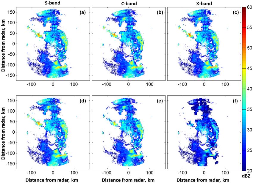
pling volumes at ranges > 14 km (Curtis, 2009). arranged in a plane in rectangular, square, circular, or elliptic
Typical scan sequence in less than 2 s time interval would shape defines a planar array.
consist of three types of scans: (i) dual Doppler, (ii) dual The radiation pattern of a planar array is characterized by
Doppler and dual polarization, and (iii) surveillance. Dual- directivity, 3 dB beam width, side lobe level, and cross-polar
Doppler mode will be the primary mode of operation. In this isolation. Radiation characteristics of rectangular, square,
mode, each of the four AESAs will generate a single “pencil” and circular planar arrays with crossed dipole element as
beam that will be scanned in azimuth and elevation. Scan- a radiating element are studied and are depicted in Fig. 5.
ning in azimuth will be between two fixed angles: one fore Available maximum fuselage area for AESA on a C-130 air-
and one aft. The fore and aft azimuth angles will be sep- craft is elliptically shaped with major and minor axes of 1.93
arated by 35◦ (Vivekanandan et al., 2014). Each of the 25 and 1.78 m, respectively. This area could hold about 3562
elevation angles will be covered with about 25 independent radiating elements at half-wavelength spacing. At C-band
pulse pair radar measurements at each beam position in 1 s. center frequency of 5.45 GHz, the half-wavelength spacing
Dual-polarimetric measurements will be collected by trans- is 2.75 cm. Figure 6 shows uniformly weighted array factor
mitting alternatively in horizontal and vertical polarizations patterns for the elliptical, circular, and square apertures. The
in the fore direction in dual-polarization and dual-Doppler maximum circular area in that elliptic area accommodates
scan mode. Polarimetric measurements will be collected only 3280 radiating elements whereas a square aperture will hold
over 10 elevation angles in 0.4 s. A secondary surveillance only 2304 elements. For matched beamwidths in azimuth and
scan mode of duration 0.4 s will be interleaved every 30 to elevation, a square or circular aperture is preferred but square
60 s periodically with the primary mode to produce a “com- aperture would transmit 30 % less power than a circular aper-
posite” plan position indicator (PPI) scan which incorporates ture. Also, for a uniform illumination, the circular aperture
data from the three aft mounted AESAs and the weather has 4 dB lower peak sidelobes than a square aperture.
avoidance radar located in the nose of the aircraft. In surveil- Figure 7 shows transmit and receive patterns of the circu-
lance mode, the elevation angle is held fixed at 0◦ and the lar aperture for three different taperings: (i) uniform tapering
beam is scanned in azimuth. for both transmit and receive patterns, (ii) uniform transmit
and 30 dB Taylor taper for the receive pattern, and (iii) 15 and
30 dB Taylor tapering of transmit and receive aperture. This
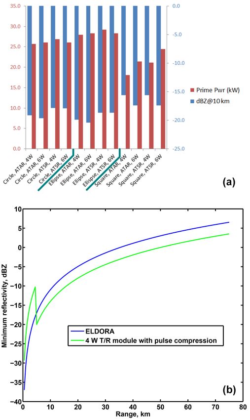
Geosci. Instrum. Method. Data Syst., 7, 21–37, 2018 www.geosci-instrum-method-data-syst.net/7/21/2018/J. Vivekanandan and E. Loew: Airborne polarimetric Doppler weather radar 29 is because the two-way antenna pattern is a product of trans- mit and receive patterns. In transmit and receive modes when all of the planar elements are tapered uniformly maximum sensitivity is realized but peak side lobe (PSL) and inte- grated sidelobes (ISL) are the highest. Lower PSL and ISL are desired for minimizing spatially disparate targets from biasing the measurement of interest. When transmit and re- ceive apertures are tapered, PSL and ISL are minimum but sensitivity is lower by 1.6 dB when compared to uniform tapering of aperture in transmit and receive modes. As ex- pected, the receiver pattern has a lower sidelobe but its main beam is broader. Typically, in the receive mode nonuniform weighting across planar array is applied for realizing a lower sidelobe and the uniform transmit weighting is applied for realizing maximum-power aperture factor, and the resultant two-way pattern is expected to have a desired lower sidelobe. When receive aperture is tapered 30 dB and maximum power is transmitted by uniform weighting of the aperture, relative sensitivity is decreased only slightly and PSL and ISL are lowered by 8 and 10 dB, respectively. 7 Radar sensitivity and prime power The limited supply of aircraft power (prime power) available for the phased array system results in very real limitations on radar performance. Prime power for the four AESAs on the NSF/NCAR C-130 is limited to 30 KW. Since the primary mission of airborne weather radar is to sample hydrometeors, scan coverage of the top and bottom AESAs can be limited to 25 km and ground level, respectively. This effectively re- duces the combined duty cycle on receive for all four AESAs to ∼ 60 %, thus conserving prime power. Figure 8a provides Figure 8. (a) Sensitivity comparison for three apertures, using two the radar sensitivity for the three apertures considered, for T/R module architectures (ATAR, ATSR) and two different HPAs both ATAR and ATSR TR module architectures and for both (4, 6 W). (b) Sensitivity of APAR as a function of range. 4 and 6 W peak-power HPAs. In several cases, transmit duty cycle was reduced to meet prime-power constraints, resulting in reduced sensitivity at 10 km. ∼ 9 dB less sensitive than the pulse compression region. This The prime power is estimated based on the preliminary sensitivity loss can be mitigated by optimally positioning the characterization of a “brick” T/R module that has been de- aircraft to maximize the sensitivity of the areas of greatest in- veloped in-house (Salazar et al., 2013). The microwave cir- terest. Care must also be taken to merge the data between the cuit technology employed in this T/R module is GaAs. The two regions, as pulse compression filtering effects can cause T/R module is comprised of discrete MMICs arranged in an artifacts in the data if not handled properly. Long pulse is ATAR architecture. The following conclusions can be drawn used, enhancing sensitivity via pulse compression. It is note- from this exercise: (i) the square aperture provides the worst worthy that the desired sensitivity of −11 dBZ at 10 km is sensitivity, (ii) the use of an ATSR architecture results in achievable in either ATSR or ATAR mode in any of the three ∼ 3 dB loss in sensitivity for a given aperture choice, and aperture configurations with 6 or 4 W HPAs. (iii) the sensitivity of the circular aperture is < 1 dB worse than that of an elliptical aperture operated with the same T/R module architecture and HPA. Figure 8b shows the sensitiv- 8 Radar architecture ity of the APAR as a function of range as depicted by the green curve. The discontinuity in the curve shows the sen- PAR elements could be distinctly configured in three types sitivity difference caused by the transition from short pulse of architecture: (i) analog, (ii) hybrid (i.e., combination of mode to pulse compression mode. In this illustration, the analog and digital), and (iii) digital. In an analog array RF short pulse region extends to 5 km in range and would be phase shifters and attenuators are used for steering the beam www.geosci-instrum-method-data-syst.net/7/21/2018/ Geosci. Instrum. Method. Data Syst., 7, 21–37, 2018
30                                            J. Vivekanandan and E. Loew: Airborne polarimetric Doppler weather radar

Table 2. Comparison between analog and digital architectures.

  Attributes          Analog                                                    Digital
  Hardware            RF phase shifters and attenuators are analog. Analog      Phase shifters and attenuators are implemented by dig-
                      phase are expensive and performance varies with tem-      ital operations: no quantization effects enable precise
                      perature and between T/R modules                          phase and amplitude control
  Antenna             Fixed for specified transmit and receive modes; depends   Fully re-configurable in post-processing; multiple
  beamwidth           on aperture weighting                                     beams could be formed
  sidelobe and gain
  Receiver            Single receiver chain; simple and inexpensive             Multiple distributed receivers. Dynamic range Improve-
                                                                                ment: 10log10 (N). Increased complexity and expense
  Digitization of     Weighted sum of N radiating element received signal       Complete access to N antenna element signals
  the received
  signals
  Calibration and     Performance of RF Phase shifters and attenuators are      Linear and robust performance
  data quality        sensitive to temperature
  Data rate           100 MB s−1                                                4 GB s−1

(Herd and Convey, 2016). The performance of RF compo-                  The antenna beam could be contiguously steered in eleva-
nents are sensitive to temperature and their precision is lim-         tion. The surveillance scan could not be realized in this con-
ited by the quantization or number of bits that are used to            figuration as the beams could not be steered contiguously in
represent phase and attenuation. Beamforming is achieved               azimuth. Figure 9c shows a hybrid architecture with no vari-
by summing signals from individual receive elements by an              able phase shifters and attenuators. This configuration allows
analog combiner. The front-end analog combiner fixes an-               digital beamforming in elevation but does not allow scan-
tenna beamwidth and sidelobes and they cannot be modi-                 ning in the azimuthal direction. Table 2 summarizes salient
fied. In a fully digital array, RF phase shifters and attenuators      features of analog and digital architectures. Based on the
are replaced by complex multiplication using digital elec-             technical specification described in Table 1, the data rate for
tronics. As digital-electronics-based complex multiplication           analog configuration is 100 MB s−1 whereas the digital ar-
is relatively immune to quantization effects, precise control          ray radar in 1-D hybrid architecture with no variable phase
of phase and amplitude is realized. Each antenna element is            shifters and attenuators would generate 4 GB s−1 data rate.
coupled to individual receiver–exciters. In a digital array, an        These data rates are many orders of magnitude larger than
analog-to-digital converter is placed in front end of the every        a dual-channel polarimetric mechanically scanning radar as
RF element. The received signals are digitized at the element          S-Pol (Lutz et al., 1997) that generates 8 MB s−1 . Since the
level and they are converted to complex baseband (I/Q) sam-            configuration shown in Fig. 9b and c uses fixed phase shifters
ples.                                                                  for steering the beam in two fixed azimuth directions, they
   Data rates of fully digital array radar are many orders of          are not capable of scanning in azimuth.
magnitude larger than a comparable analog array. An hybrid                Not having continuous beam steering capability in az-
architecture using a combination of analog and digital beam-           imuth limits acquisition of a composite PPI “surveillance”
former could reduce the date rate to a manageable level for            scan from either side of the fuselage radars, which are located
real-time data processing.                                             on the upper portion of the tail ramp radars in combination
   Examples of analog, hybrid, and digital array architec-             with C-130 weather avoidance radar (Vivekanandan et al.,
tures are illustrated in Fig. 9. Analog beamformer using               2014). This “surveillance” mode is essential to provide safety
RF phase shifters and attenuators in ATAR configuration is             in single aircraft missions and will also aid in mission flight
shown Fig. 9a. Beams could be steered to contiguous az-                planning while in the air. The PAR on top of the fuselage
imuth and elevation angles. The number of variable phase               could be operated as an end-fire array for the acquisition of
shifters and attenuators could be reduced by the square root           surveillance scan. It should be noted that not having a broad-
of number of the number of elements by using fixed phase               side array on top of the fuselage limits dual-Doppler scans
shifters as shown in Fig. 9b. For steering the beam between            that are suitable for retrieving vertical winds over the head
two discrete beam positions separated by 35◦ , fixed phase             storms. End-fire PAR has lower gain compared to a broadside
shifters are used. As alluded to earlier, 2-D winds will be            array. Re-directing the usage of the radar on top of the fuse-
measured using the fore and aft beams separated by 35◦ .               lage would diminish redundancy in APAR’s ability to collect

Geosci. Instrum. Method. Data Syst., 7, 21–37, 2018                         www.geosci-instrum-method-data-syst.net/7/21/2018/
J. Vivekanandan and E. Loew: Airborne polarimetric Doppler weather radar 31
Figure 9. APAR architectures for ATAR configuration: (a) 2-D analog, (b) 1-D analog, and (c) 1-D hybrid.
volume scans. Instead of a PAR, a mechanically scanning anechoic chamber. The equipment, if any, required for field
radar as in the NOAA P-3 could provide a dedicated surveil- project calibration must be compact and transportable. The
lance scan feature. Potential usefulness of end-fire PAR and field calibration of a single array must be able to be com-
mechanically scanning radar for surveillance scan applica- pleted within 10 h, including any setup or teardown of equip-
tion will be investigated in the future. Additional studies are ment.
necessary for understanding pros and cons of operating the Reflectivity can be calibrated using a known signal source
radar on top of the fuselage in broadside and end-fire config- such as transmit power from a horn antenna in the far zone
urations. or the solar radiation. When a known external signal source
is used, the radar does not transmit, and only the receiver
system is calibrated. In the case of solar calibration (Tap-
9 Calibration of reflectivity ping, 2001), the receiver should be sensitive enough to de-
tect the low signal power (−100 dBm). Also, the main lobe
Weather radar applications place high demands on phased beam width should be less than 0.5◦ for satisfying the beam-
array calibration. It is critical to accurately know the gain, filled condition. In the transmit and receive mode, a highly
beamwidth, and pointing angle of the array over a variety of reflective test sphere suspended from a tethered balloon can
operating conditions. Calibration is divided into three phases: be used as a known reference target for calibration. However,
(i) characterization, (ii) field calibration, and (iii) end-to- the sphere being a point target does not fill the radar beam; as
end calibration using an external target such as the sun or a a result, only the on-axis gain of the beam is measured. Self-
rain medium. Characterization is performed under controlled consistency among Z, ZDR , and KDP can be used for cal-
conditions in an anechoic chamber. It is done prior to the ar- ibrating the radar system (Vivekanandan et al., 2003). One
rays being put in service or after any major component failure of the advantages of using power and phase measurements
or repair. Field calibration is done in situ on the aircraft. It is from a single radar is the elimination of sampling volume
performed after the arrays are installed on the aircraft prior differences among the measurements. At C band, ZHH and
to a field project or during a field project after a repair has ZDR must be corrected for attenuation and differential atten-
been made. Field calibration must be able to compensate for uation prior to calibration based on self-consistency among
component drift as well as any performance variations due to radar measurements. Attenuation and differential attenuation
the departure of the installation environment from that of the
www.geosci-instrum-method-data-syst.net/7/21/2018/ Geosci. Instrum. Method. Data Syst., 7, 21–37, 201832 J. Vivekanandan and E. Loew: Airborne polarimetric Doppler weather radar
and V antenna port primarily transmits vertically polarized
fields, and all electric fields on the right side of the above
equation are normalized by their respective broadside elec-
(h) (h)
tric fields (e.g., Eφ (θ, φ) or Eθ (θ, φ) is normalized by
(h) π
E ( 2 , 0)).
The projection matrix for microstrip patch antenna is (Lei
et al., 2015)
sin θ · g (h) (θ, φ) cos θ sin φ · g (v) (θ, φ)
P= , (4)
0 cos φ · g (v) (θ, φ)
Figure 10. The coordinate system for electric fields from a pair of where radiation fields of microwave patch antenna
h (v) (h) (v) (h)
microstrip radiating elements. M is the magnetic current density Eφ (θ, φ), Eφ (θ, φ), Eθ (θ, φ), and Eθ (θ, φ) are
v
of a horizontally polarized radiating element. M is the magnetic
related to g (h) (θ, φ) and g (v) (θ, φ) (Balanis, 1997). The
current density of a vertically polarized radiating element hydrome-
projection matrix, P, couples oblique fields E h and E v to
teors are located at range r. Unit vectors ar , aθ , and aϕ form a local
orthogonal system at r (Lei et al., 2015). the local H and V coordinates at the scatterer and at the
ESA aperture. The horizontally polarized field is a function
of sin(θ ) and vertically polarized field is a sum of intrinsic
could be obtained from propagation measurement or a vari- vertically polarized weighted by cos(ϕ) and a leakage term
ational method that use both ZDR and KDP measurements from cross polarization (V ) weighted by cos(θ ) sin(ϕ).
(Chang et al., 2014). The cross-coupling term p21 could be neglected as cross-
polarization isolation for a microstrip antenna is typically
lower than 20 dB. The backscattered field, Er , in the local H
10 Removal of bias in polarimetric radar and V directions is a product of Et and backscatter matrix
measurements S. The received field Er at the ESA aperture in alignment
with H and V channels is a product of P and Er . The
In the case of a mechanically steered antenna, the hori-
backscattering matrix is
zontally and vertically polarized beams preserve intrinsic
source polarimetric response independent of the beam di- S(p) T 0
≡ P S P
rection. Since orthogonality between H and V polarization
2 s 0 + p 2 s 0 + p p (s 0 + s 0 )
p11 hh 21 vv 11 21 vh hv
0 + p p s 0 + p p s 0 + p p s 0 ,
p11 p12 shh (5)
is desired for estimating cloud microphysical measurements =
21 22 vv 11 22 hv
0 + p p s0 + p p s0 + p p s0
12 21 vh
p11 p12 shh 21 22 vv 11 22 vh 12 21 hv
of hydrometeors, radiation fields in dual-polarization radar 2 s 0 + p 2 s 0 + p p (s 0 + s 0 )
p12 hh 22 vv 12 22 vh hv
are transmitted orthogonally to each other. In an ESA when
a beam is steered electronically away from the boresight, where S0 the intrinsic backscatter matrix is
the transmitted field is biased as a function of scan angle 0 0
and cross coupling between dual-polarization sources occurs shh shv
S0 = 0 0 .
(Zhang et al., 2009). Figure 10 illustrates a spherical coordi- svh svv
nate system of planar array and hydrometeor scattering loca-
tion at range r. In an ATSR mode alternately transmitted H and V pulses
The relations among transmit polarization field vectors at are used for retrieving radial velocity and polarimetric radar
the planar aperture, incident field vectors on a hydrometeor, estimates. The above matrix is rewritten to take into account
and received fields can be described using the following lin- the Doppler phase shift between H and V pulse period as
(p)
ear transformation. The transmitted electric fields, E th and "
(p) (p)
#
(p) s (2i) s (2i + 1)
E tv , are generated by radiation sources Mh and Mv and pro- S(p) = hh
(p)
hv
(p)
jected onto the local H and V directions: svh (2i) svv (2i + 1)
" #
(p) (p)
"
(p)
# shh (2i) e−j 2k0 v̂Ts · shv (2i)
Eiφ Eth = (p) (p) . (6)
Ei =
−Eiθ
=P (p) = PE t , (2) svh (2i) e−j 2k0 v̂Ts · svv (2i)
Etv
where the projection matrix P is (Lei et al., 2015) Since the projection matrix term p21 is zero, the individual
elements of the received backscatter at the ESA are
" (h) (v)
#
p11 p12 Eφ Eφ (p)
P= = (h) (v) , (3) 2 0
shh (2i) = p11 shh (2i), (7)
p21 p22 −Eθ −Eθ
(p) 0 0
svh (2i) = p11 p12 shh (2i) + p11 p22 svh (2i), (8)
where the superscripts define H and V antenna ports. The H
(p) 0 0
antenna port primarily transmits horizontally polarized fields shv (2i + 1) = p11 p12 shh (2i + 1) + p11 p22 shv (2i + 1), (9)
Geosci. Instrum. Method. Data Syst., 7, 21–37, 2018 www.geosci-instrum-method-data-syst.net/7/21/2018/J. Vivekanandan and E. Loew: Airborne polarimetric Doppler weather radar 33
Figure 11. Biases in ZDR , 8DP , ρHV , and LDR as a function azimuth and elevation scan angle of the radar beam.
(p) 2 0 2 0
svv (2i + 1) = p12 shh (2i + 1) + p22 svv (2i + 1) is positively biased. For both positive and negative eleva-
0
+ p12 p22 (svh 0
(2i + 1) + shv (2i + 1)). (10) tion angles ZDR is biased negatively and it varies with the
azimuth angle. For azimuth and elevation angles < 20◦ , the
In the ATSR mode, this is a set of linear equations (Zrnić bias is < 0.25 dB. 8DP and ρhv exhibit no bias for 0◦ ele-
et al., 2011). The intrinsic scattering matrix elements are es- vation and the bias is less than 1◦ for elevation and azimuth
timated as projection matrix P and to backscatter measure- angles < 20◦ . Bias in ρhv is less than 1 % for elevation an-
ments SP . The element at 2i + 1 time interval is related to gle < 20◦ . Bias in LDR significantly increases as the beam
the element at 2i by the Doppler phase shift ej 2k0 v̂Ts . The scanned away from bore sight. For elevation angle < 5◦ and
Doppler shift and 8DP are estimated from cross correlation azimuth angle < 20◦ LDR is < −30 dB.
between consecutive estimates of co-polarization scattering
amplitudes. Unbiased estimates of polarimetric observables
require calibrated transmit amplitudes. Thus pulse-pair meth- 11 Summary
ods can be used for estimating unbiased Doppler and po-
larimetric measurements, provided transmit amplitudes are APAR with dual-polarimetric and dual-Doppler capability
known. allows concurrent estimates of microphysical (e.g., precipi-
Once the backscatter amplitudes are estimated using the tation types and sizes, quantitative precipitation estimation)
above equations, all of the polarimetric variables could be and 3-D winds in a precipitation system. At present, no
derived (Zrnić et al., 2011). The bias in polarimetric mea- other instrument other than an airborne polarimetric Doppler
surements is estimated for radar resolution volume populated phased array radar system has the potential to estimate 3-D
with spherical hydrometeor with a baseline ρhv of 0.9. The winds and microphysics concurrently. Both ATAR and ATSR
estimated bias depends on radiation pattern of the radiating polarimetric configurations require the same amount of time
element. The effect of the array factor is not considered in for acquiring ZDR , 8DP , and ρHV . An additional receive
this study. channel in ATSR enables measurement of LDR at a faster
The bias is estimated for stacked patch microstrip antenna pace but the ATSR configuration requires twice the amount
radiation element described in Lei et al. (2015). Figure 11 of receiver elements compared to the ATAR configuration.
shows that biases in ZDR , 8DP , ρhv , and LDR are symmet- Multiple AESA radars on the C-130 fuselage enhance spa-
rical with respect to changes in azimuth and elevation an- tial and temporal resolutions of measurements. Solid-state,
gles. For 0◦ elevation, as the azimuth angle increases, ZDR compact T/R elements based on GaAs or GaN is the key en-
www.geosci-instrum-method-data-syst.net/7/21/2018/ Geosci. Instrum. Method. Data Syst., 7, 21–37, 201834 J. Vivekanandan and E. Loew: Airborne polarimetric Doppler weather radar abling technology; only demonstrated hardware and software Methodologies for estimating polarimetric observables are subsystems will be included in the design of the AESA. summarized based on the earlier published results. Biases in Agile beam steering using the e-scan feature enables the ZDR , 8DP , ρhv , and LDR due to cross coupling between collection of more independent samples in a specified time dual-polarization sources are symmetrical with respect to interval when compared to a mechanically scanning radar. changes in azimuth and elevation angles and they are with Since an airborne radar has a limited amount of time to in acceptable range for microphysical studies for azimuth collect measurements over a specified sample volume, agile and elevation angles < 20◦ . In an alternate transmit mode, beam steering reduces uncertainty in radar measurements. the received voltages are a set of linear equations and can be For the maximum available area for AESA on a C-130 solved either by pulse-to-pulse adjustment or powers and cor- aircraft, elliptical and circular apertures produce almost the relations of received voltages. Radial wind and polarimetric same directivity, but the circular planar array is more desir- observables can be estimated from correlations of received able. For uniform illumination, the circular aperture has 3 dB voltages. Self-consistency among ZHH , ZDR , and KDP will lower peak sidelobe than a rectangular or square aperture. be used for absolute calibration of reflectivity. This would Unlike elliptic, square, or rectangular planar arrays, distor- require unbiased ZDR and attenuation corrected reflectivity. tions in the array pattern of a circular array due to mutual coupling effect are the same for each element and this makes it easier to deal with the mutual coupling effect. With re- Code and data availability. The software used in this publication spect to sensitivity, the elliptical aperture with 6 W HPA of- can be obtained by sending an email to vivek@ucar.edu. fers ∼ 1 dB better sensitivity than the circular aperture and ∼ 3 dB better than the square aperture. Circular aperture of- fers matched beams in horizontal and vertical polarization transmission. Phased array radar architecture is evolving toward a com- bination of analog and digital (hybrid) and fully digital ar- chitecture. From the perspective of robust performance, im- proved data quality, and adaptive beam forming, digital array architecture is preferred. Since digital array radar produces higher data rates, practical requirements for processing high data rates need to be evaluated. Geosci. Instrum. Method. Data Syst., 7, 21–37, 2018 www.geosci-instrum-method-data-syst.net/7/21/2018/
J. Vivekanandan and E. Loew: Airborne polarimetric Doppler weather radar                                         35

Appendix A: List of acronyms

 AESA       Active electronically scanned array
 APAR       Airborne phased array radar
 ATAR       Alternate transmit and alternate receive
 ATSR       Alternate transmit and simultaneous receive
 C-130      Four-engine turboprop military transport aircraft
 dBZ        Radar reflectivity factor
 ELDORA     Electra Doppler radar
 Electra    Turboprop airliner
 EOL        Earth Observing Laboratory
 e-scan     Electronic scanning
 FPGA       Field-programmable gated array
 H          Horizontal
 HPA        High-power amplifier
 ICPR       Integrated cross-polar ratio
 KDP        Specific propagation phase
 LNA        Low noise amplifier
 LDR        Linear depolarization ratio
 PA         Power amplifier
 MMIC       Monolithic microwave integrated circuits
 NCAR       National Center for Atmospheric Research
 NOAA       National Oceanic and Atmospheric Administration
 NSF        National Science Foundation
 PAR        Phased array radar
 PPI        Plan position indicator
 PRF        Pulse repetition frequency
 P-3        Four-engine turboprop surveillance aircraft
 RF         Radio frequency
 Rx         Receiver
 SNR        Signal-to-noise ratio
 STSR       Simultaneously transmit and simultaneously receive
 TD         Time to independence
 T/R        Transmit–receive
 Tx         Transmitter
 V          Vertical
 ZHH        Reflectivity
 ZDR        Differential reflectivity
 8DP        Propagation phase

www.geosci-instrum-method-data-syst.net/7/21/2018/               Geosci. Instrum. Method. Data Syst., 7, 21–37, 2018
36                                               J. Vivekanandan and E. Loew: Airborne polarimetric Doppler weather radar

Competing interests. The authors declare that they have no conflict     Herd, J. S. and Convey, M. D.: The evolution of modern phased
of interest.                                                              array architecture, P. IEEE, 104, 519–529, 2016.
                                                                        Hildebrand, P. H., Lee, W.-C., Walther, C. A., Frush, C., Ran-
                                                                          dall, M., Loew, E., Neitzel, R., Parsons, R., Testud, J.,
Acknowledgements. The National Science Foundation primarily               Baudin, F., and LeCornec, A.: The ELDORA/ASTRAIA air-
funds NCAR. This material is based upon work supported by the             borne Doppler weather radar: High resolution observations from
National Science Foundation under cooperative grant numbers               TOGA COARE, B. Am. Metorol. Soc., 77, 213–232, 1996.
NSF0015 and MO904552. The authors are grateful to Guifu Zhang           Lhermitte, R.: A 94-GHz Doppler radar for cloud observations, J.
and Lei Lei of University of Oklahoma, Norman, OK, for providing          Atmos. Ocean. Tech., 4, 36–48, 1987.
the software for estimating bias in polarimetric radar observations.    Lei, L., Zhang, G., Doviak, R., and Karimkashi, S.: Comparison
Wei-Yu Chang of Chinese Cultural University, Taipei, Taiwan,              of theoretical biases in estimating polarimetric properties of pre-
performed model computations shown in Fig. 3. We would also               cipitation with weather radar using parabolic reflector or planar
like to acknowledge the contributions of Bernard Hwang for his            and cylindrical arrays, IEEE T. Geosci. Remote Sens., 53, 4313–
work in the redesign and characterization of the T/R module PCB.          4327, 2015.
The support of Wen-Chau Lee, James Moore, and Peisang Tsai              Lutz, J., Rilling, B., Wilson, J., Weckwerth, T., and Vivekanandan,
of NCAR is recognized. Any opinions, findings, and conclusions            J.: S-Pol after three operational deployments, technical perfor-
or recommendations expressed in this material are those of the            mance, siting experiences, and some data examples, Preprints,
author(s) and do not necessarily reflect the views of the National        28th Conf. on Radar Meteorology, Austin, TX, 7–12 September,
Science Foundation.                                                       Amer. Meteor. Soc., Boston, 286–287, 1997.
                                                                        Salazar, J. L., Medina, R. H., and Loew, E.: T/R modules for ac-
Edited by: Mehrez Zribi                                                   tive phased array radars, IEEE Phased array radar conference,
Reviewed by: Jacques Testud and one anonymous referee                     Waltham, MA, 2013.
                                                                        Smith, R. B., Carbone, R. E., and Zeng, X.: The lower at-
                                                                          mospheric observing facilities workshop – meeting the chal-
                                                                          lenges of climate system sciences, 18–19 June 2012, Boulder,
References                                                                CO, USA, 44 pp., available at: https://www.eol.ucar.edu/system/
                                                                          files/LAOF_Workshop_Report_FINAL_06112013.pdf (last ac-
Balanis, C. A.: Antenna theory: analysis and design, 2nd Edn., Wi-        cess: January 2018), 2012.
  ley, xvi, 941 pp., New Jersey, USA, 1997.                             Tapping, K.: Antenna calibration using the 10.7 cm solar flux.
Bluestein, H. B. and Wakimoto, R. M.: Mobile radar observations of        Preprints, Workshop on Radar Calibration, Albuquerque, NM,
  severe convective storms, Vol. 52, Meteorological Monographs,           13–14 January, Amer. Meteor. Soc., Boston, 32 pp., 2001.
  American Meteorological Society, 105–136, 2003.                       Vivekanandan, J., Zhang, G., Ellis, S. M., Rajopadhyaya, D.,
Brandes, E. A., Zhang, G., and Vivekanandan, J.: Comparison of            and Avery, S. K.: Radar reflectivity calibration using differ-
  polarimetric radar drop size distribution retrieval algorithms, J.      ential propagation phase measurement, Radio Sci., 38, 8049,
  Atmos. Ocean. Tech., 21, 584–598, 2004.                                 https://doi.org/10.1029/2002RS002676, 2003.
Bringi, V. N. and Chandrasekar, V.: Polarimetric Doppler Weather        Vivekanandan, J., Zhang, G. F., and Brandes, E. A.: Polarimetric
  Radar, Cambridge University Press, New York, 2001.                      radar estimators based on a constrained gamma drop size distri-
Bringi, V. N., Chandrasekar, V., Balakrishnan, N., and Zrnić, D.: An     bution model. J. Appl. Meteorol., 43, 217–230, 2004.
  Examination of Propagation Effects in Rainfall on Radar Mea-          Vivekanandan, J., Lee, W.-C., Loew, E., Salazar, J. L., Grubišic, V.,
  surements at Microwave Frequencies, J. Atmos. Ocean. Tech., 7,          Moore, J., and Tsai, P.: The next generation airborne polarimetric
  829–840, 1990.                                                          Doppler weather radar, Geosci. Instrum. Method. Data Syst., 3,
Clothiaux, E. E., Miller, M. A., Albrecht, B. A., Ackerman, T. P.,        111–126, https://doi.org/10.5194/gi-3-111-2014, 2014.
  Verlinde, J., Babb, D. M., Peters, R. M., and Syrett, W. J.: An       Wang, H., Fang, D., and Chow, Y. L.: Grating lobe reduction in a
  evaluation of a 94-GHz radar for remote sensing of cloud prop-          phased array of limited scanning, IEEE Trans. Antenn. Propag.,
  erties, J. Atmos. Ocean. Tech., 12, 201–229, 1995.                      56, 1581–1585, 2008.
Chang, W., Vivekanandan, J., and Wang, T.-C. C.: Estimation of X-       Wang, Y. and Chandrasekar, V.: Polarization isolation requirements
  band Polarimetric Radar Attenuation and Measurement Uncer-              for linear dual-polarization weather radar in simultaneous trans-
  tainty Using a Variational Method, J. Appl. Meteorol., 53, 1099–        mission mode of operation, IEEE T. Geosci. Remote Sens., 44,
  1119, 2014.                                                             2019–2028, 2006.
Curtis, C. D.: Exploring the capabilities of the agile beam phased      Weber, M. E., Cho, J. Y. N., Herd, J. S., Flavin, J. M., Benner, W.
  array weather radar, PhD Dissertation, University of Oklahoma,          E., and Torok, G. S.: The Next-Generation Multimission U.S.
  2009.                                                                   Surveillance Radar Network, B. Am. Meteorol. Soc., 88, 1739–
Doviak, R. J. and Zrnic, D.: Doppler radar and weather observa-           1751, 2007.
  tions, Academic Press, San Diego, California, USA, 562 pp.,           Yu, T.-Y., Orescanin, M. B., Curtis, C. D., Zrnić, D. S., and Forsyth,
  1993.                                                                   D. E.: Beam multiplexing using the phased-array weather radar,
Girardin-Gondeau, J., Baudin, F., and Testud, J.: Comparison of var-      J. Atmos. Ocean. Tech., 24, 616–626, 2007.
  ious coded waveforms for an airborne meteorological Doppler           Zhang, G.: Weather Radar Polarimetry, Boca Raton, CRC Press,
  radar, J. Atmos. Ocean. Tech., 8, 234–246, 1991.                        253–277, 2017.

Geosci. Instrum. Method. Data Syst., 7, 21–37, 2018                         www.geosci-instrum-method-data-syst.net/7/21/2018/
You can also read