AIRCRAFT SERIOUS INCIDENT INVESTIGATION REPORT - AI2018-5
←
→
Page content transcription
If your browser does not render page correctly, please read the page content below
AI2018-5

AIRCRAFT SERIOUS INCIDENT
  INVESTIGATION REPORT

     JETSTAR JAPAN CO., LTD.
            JA0 4 J J

           August 30, 2018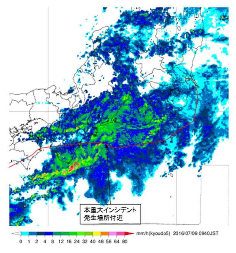
The objective of the investigation conducted by the Japan Transport Safety Board in accordance
with the Act for Establishment of the Japan Transport Safety Board and with Annex 13 to the
Convention on International Civil Aviation is to prevent future accidents and incidents. It is not the
purpose of the investigation to apportion blame or liability.

                                                                Kazuhiro Nakahashi
                                                                Chairman
                                                                Japan Transport Safety Board

                                                     Note:
     This report is a translation of the Japanese original investigation report. The text in Japanese shall
prevail in the interpretation of the report.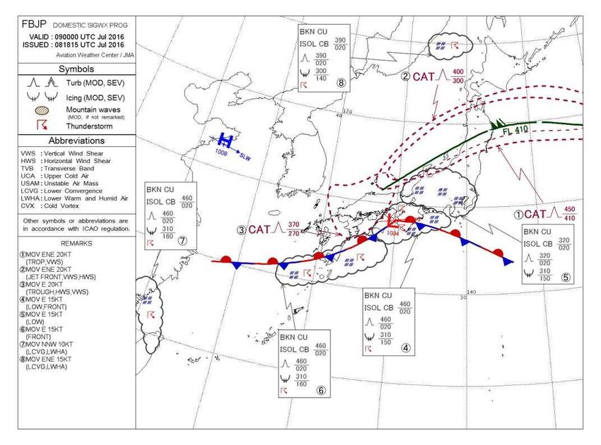
AIRCRAFT SERIOUS INCIDENT
                          INVESTIGATION REPORT

UNRELIABLE AIRSPEED ON BOTH THE CAPTAIN’S SIDE AND THE
                    CO-PILOT’S SIDE
 AT AN ALTITUDE OF 37,000 FT, 96 KM SOUTH-SOUTHEAST OF
        CHUBU CENTRAIR INTERNATIONAL AIRPORT
                AT 09:38 JST, JULY 9, 2016

                               JETSTAR JAPAN CO., LTD.
                                AIRBUS A320-232, JA04JJ

                                                                                     July 27, 2018
                                                    Adopted by the Japan Transport Safety Board
                                                             Chairman      Kazuhiro Nakahashi
                                                              Member       Toru Miyashita
                                                              Member       Toshiyuki Ishikawa
                                                              Member       Yuichi Marui
                                                              Member       Keiji Tanaka
                                                              Member       Miwa Nakanishi

                                           SYNOPSIS

<Summary of the Serious Incident>
     On Saturday, July 9, 2016, Airbus A320-232, registered JA04JJ, operated by Jetstar Japan
Co., Ltd., was flying as a regularly scheduled 502 flight of the company, which departed from
Fukuoka Airport and was heading to Narita International Airport. When the aircraft was flying at
an altitude of 37,000ft and approximately 96km south-southeast of Chubu Centrair International
Airport, the airspeed indication temporarily failed on the Captain's side and the Co-Pilot's side from
09:38 Japan Standard Time (JST: UTC + 9 hrs). After that, the aircraft descended to an altitude of
25,000ft and continued flight. It landed at Narita International Airport at 10:26.
     There were 156 persons on board consisting of the captain, five other crewmembers, and 150
passengers. There were no injuries.
     There was no damage to the aircraft.
<Probable Causes>
     It is probable that this serious incident occurred because the icing occurred in the Pitot tube
when the aircraft was flying at an altitude of 37,000ft, which led to the temporary failure of
airspeed indication on the Captain's side and Co-Pilot's side.
     It is somewhat likely that the icing of the Pitot tube occurred because the aircraft flew in an
ice crystal area that was existing in the vicinity of a cumulonimbus that grew to a high altitude.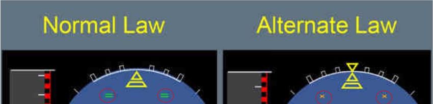
Abbreviations used in this report are as follows:
        AC                         : Advisory Circular
        AD                         : Airworthiness Directive
        ADIRU                      : Air Data/Inertial Reference Unit
        ADM                        : Air Data Module
        ADR                        : Air Data Reference
        AIM-j                      : Aeronautical Information Manual Japan
        AOA                        : Angle of Attack
        AP                         : Auto Pilot
        AT                         : Auto Thrust
        ATC                        : Air Traffic Control
        BITE                       : Built-in Test Equipment
        CAOA                       : Computed Angle of Attack
        CAS                        : Computed Airspeed
        CASISIS                    : Computed Airspeed Integrated Standby Instrument System
        CFDIU                      : Centralized Flight Data Interface and Management Unit
        CVR                        : Cockpit Voice Recorder
        dB                         : decibel
        EASA                       : European Aviation Safety Agency
        ECAM                       : Electronic Centralized Aircraft Monitoring
        ELAC                       : Elevator Aileron Computer
        FCOM                       : Flight Crew Operation Manual
        FCTM                       : Flight Crew Techniques Manual
        FDR                        : Flight Data Recorder
        FL                         : Flight Level
        IR                         : Insulation Resistance
        JST                        : Japan Standard Time
        MAC                        : Mean Aerodynamic Chord
        NCD                        : Non Computed Data
        ND                         : Navigation Display
        PFD                        : Primary Flight Display
        QAR                        : Quick Access Recorder
        QRH                        : Quick Reference Handbook
        SAT                        : Static Air Temperature
        TAT                        : Total Air Temperature
        TL                         : Thrust Lever
        UTC                        : Universal Time Coordinate
  Unit Conversion Table
        1 ft                       : 0.3048 m
        1 in                       : 25.40 mm
        1 nm                       : 1,852 m
        1 lb                       : 0.4536 kg
        1 kt                       : 1.852 km/h (0.5144 m/s)
        1 atm                      : 29.92 inHg                : 1,013 hPa
        55 dBZ                     : 100 mm/h

                                                    -i-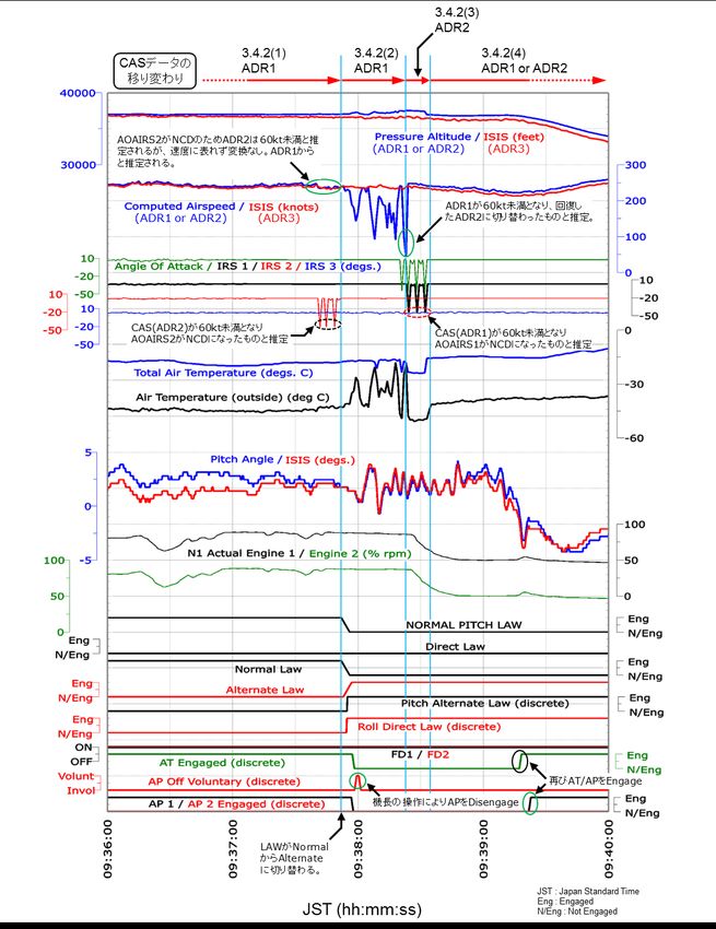
Table of Contents
                                                                                    Page
1. PROGRESS AND PROGRESS OF THE AIRCRAFT SERIOUS INCIDENT                           1
  INVESTIGATION
1.1 Summary of the Serious Incident                                                 1
1.2 Outline of the Serious Incident Investigation                                   1
 1.2.1 Investigation Organization                                                   1
 1.2.2 Representatives of the Relevant State                                        1
 1.2.3 Implementation of the Investigation                                          1
 1.2.4 Comments from the Parties Relevant to the Cause of the Serious Incident      1
 1.2.5 Comments from the Relevant State                                             1

2. FACTUAL INFORMATION                                                              1
2.1 History of the Flight                                                           2
 2.1.1 History of the Flight based on Air Traffic Control Communications Records,
       FDR Records, and QAR Records                                                 2
 2.1.2 Statements of Flight Crewmembers                                             4
2.2 Damage to Persons                                                               5
2.3 Damage to the Aircraft                                                          5
2.4 Flight Crewmembers Information                                                  5
2.5 Aircraft Information                                                            6
 2.5.1 Aircraft                                                                     6
 2.5.2 Weight and Balance                                                           6
 2.5.3 Records of Maintenance and Repair of the Aircraft                            6
2.6 Meteorological Information                                                      6
 2.6.1 Weather Synoptic based on Surface Weather Chart                              6
 2.6.2 Radar Observatory Data                                                       8
2.7 Flight Recorder Information                                                     9
2.8 Information on Tests and Researches                                             9
 2.8.1 Maintenance record of the Pitot Tubes                                        9
 2.8.2 Tests of the Pitot Tubes                                                     10
2.9 Additional Information                                                          10
 2.9.1 Icing                                                                        10
 2.9.2 Information on Ice Crystals                                                  10
 2.9.3 Information on Unreliable airspeed indication                                15
 2.9.4 NAV ADR DISAGREE Indication                                                  15
 2.9.5 F/CTL ALTERNATE LAW Indication                                               17
 2.9.6 Aircraft System                                                              18
 2.9.7 Messages Recorded on the Aircraft                                            18
 2.9.8 Issuance of TCD-5734B-2015                                                   19
 2.9.9 Revised regulations for Airspeed System                                      19
 2.9.10 Related Information                                                         19

                                                    - ii -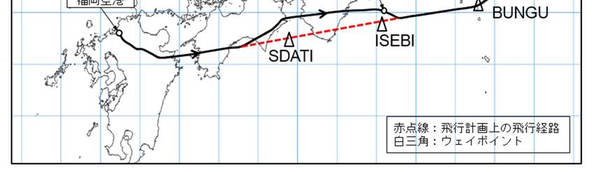
3. ANALYSIS                                                      20
3.1 Qualifications of Crewmembers                                20
3.2 Airworthiness Certificate of the Aircraft                    20
3.3 Relations to the Meteorological Conditions                   20
3.4 Events Related to the Aircraft                               20
 3.4.1 Damage to No. 2 Pitot Tubes                               20
 3.4.2 Unreliable airspeed indication                            21
3.5 Avoiding Ice Crystals                                        22

4. PROBABLE CAUSES                                               23

5. SAFETY ACTIONS                                                23
5.1 Prevention Measures of Recurrence Taken After the Incident   23
 5.1.1 Safety Actions Taken by the Company                       23

ATTACHMENT
 Appended Figure 1: A320-232 Airbus Three-View drawings          24
 Photo 2: Serious incident aircraft                              24
 Appended Figure 2: Record of FDR and others                     25

                                                 - iii -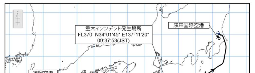
1. PROGRESS AND PROGRESS OF THE AIRCRAFT SERIOUS
INCIDENT INVESTIGATION

1.1 Summary of the Serious Incident
     On July 9 (Saturday), 2016, Airbus A320-232, registered JA04JJ, operated by Jetstar Japan
Co., Ltd., was flying as a regularly scheduled 502 flight of the company, which departed from
Fukuoka Airport and was heading to Narita International Airport. When the aircraft was flying at
an altitude of 37,000ft and approximately 96km south-southeast of Chubu Centrair International
Airport, airspeed indication temporarily failed on the Captain's side and the Co-Pilot's side from
09:38 Japan Standard Time (JST: UTC + 9 hrs, unless otherwise stated all times are indicated in
JST on a 24-hour clock). After that, the aircraft descended to an altitude of 25,000ft and continued
flight. It landed at Narita International Airport at 10:26.
     There were 156 persons on board consisting of the captain, five other crewmembers, and 150
passengers. There were no injuries.
     There was no damage to the aircraft.

1.2 Outline of the Serious Incident Investigation
     The occurrence covered by this report falls under the category of “Multiple malfunctions in one
or more systems equipped on aircraft impeding the safe flight of aircraft” as stipulated in Clause 9,
Article 166-4 of the Ordinance for Enforcement of Civil Aeronautics Act of Japan (Ordinance of the
Ministry of Transport No. 56 of July 31, 1952), and is classified as a serious incident.

1.2.1 Investigation Organization
     On July 12, 2016, the Japan Transport Safety Board (JTSB), upon receipt of the notification of
the occurrence of a serious incident, designated an investigator-in-charge and two other
investigators to investigate this serious incident.

1.2.2 Representatives of the Relevant State
     An accredited representative and an adviser of the French Republic, as the State of Design
and Manufacture of the aircraft involved in the serious incident, and an accredited representative
of the United States of America, as the State of Manufacture of parts of the aircraft, participated in
the investigation.

1.2.3 Implementation of the Investigation
     July 12-13, 2016: Interviews and aircraft examination
     August 24-25, 2016: Detailed investigation of the Pitot tubes

1.2.4 Comments from the Parties Relevant to the Cause of the Serious Incident
     Comments were invited from parties relevant to the cause of the serious incident.

1.2.5 Comments from the Relevant State
     Comments on the draft report were invited from the Relevant State.

                              2. FACTUAL INFORMATION

                                                      -1-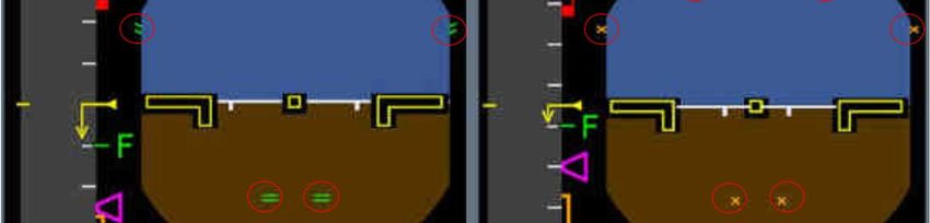
2.1 History of the Flight
      On July 9, 2016, Airbus A320-232, registered JA04JJ (hereinafter referred to as "the
Aircraft"), operated by Jetstar Japan Co., Ltd. (hereinafter referred to as "the Company"), took off,
as a regularly scheduled Flight 501 of the Company, from Narita International Airport and landed
at Fukuoka Airport. The Aircraft took off from Fukuoka Airport as a regularly scheduled Flight 502
of the Company at 08:50, and was flying back to Narita International Airport.
      There were 156 persons on board consisting of the captain (hereinafter referred to as "the
Captain"), five other crewmembers, and 150 passengers.
      When the serious incident occurred, the Captain sat in the left seat in the cockpit of the
Aircraft as the PF*1 and the Co-Pilot sat in the right seat as the PM*1.
      The flight plan of the Aircraft is outlined below:
          Flight rules: Instrument flight rules (IFR); Departure aerodrome: Fukuoka Airport;
          Estimated off-block time: 08:40; Cruising speed: 452 kt; Cruising altitude: FL*2 370;
          Route: SABAR - Y81 (RNAV route) - BINKS; Destination aerodrome: Narita International
          Airport; Total estimated elapsed time: One hour 24 minutes; Fuel load expressed in
          endurance: Two hours 40 minutes; Alternative aerodrome: Tokyo International Airport
      The history of the flight up to the time of the serious incident is summarized below, based on
the statements of the Captain and Co-Pilot, the records of the flight data recorder (hereinafter
referred to as “the FDR”), and the air traffic control communications records.

2.1.1 History of the Flight based on Air Traffic Control Communications Records, FDR*3 Records
and QAR*4 Records
      Around 09:14       When the Aircraft was flying at FL370, it requested Fukuoka Control for a
                         course deviation 20 nm north from the scheduled route to avoid adverse
                         weather conditions, and received an approval.
      Around 09:20       The Aircraft requested that it deviate another 5 nm northward to avoid
                         adverse weather conditions, and received an approval.
      09:23:16           The Aircraft told Tokyo Control that the deviation of 25 nm northward for
                         avoiding adverse weather conditions had been approved. Tokyo Control
                         instructed the Aircraft to report when the Aircraft could make a direct flight
                         to BUNGU (waypoint).
      09:30:18           The Aircraft requested a direct flight to BUNGU, which was approved.
      09:33:11           The Aircraft requested a deviation of 25 nm southward for avoiding adverse
                         weather conditions, which was approved.
      09:36:18           The Aircraft reported its location as FL370 above ISEBI (waypoint).
      09:37:07           Tokyo Control asked if the Aircraft could fly direct to BUNGU. However, the

*1 “PF (Pilot-Flying)” and “PM (Pilot-Monitoring)” are terms used to identify pilots based on their roles on an
  aircraft flown by two pilots. The PF is mainly in charge of flying. The PM is mainly in charge of monitoring of the
  flight conditions of the aircraft, cross-checking of the operation by the PF, and duties other than flying.
*2 “FL” stands for Flight Level. It is the pressure altitude in the standard atmosphere. The FL is expressed in the
  value dividing the reading on the altimeter by 100, when the altimeter is set to 29.92 inHg. In Japan, flight level
  is usually used at flight altitudes of 14,000 ft or higher. For example, FL200 represents the altitude of 20,000 ft.
*3 See 2.7 for the description of “FDR”.
*4 “QAR” stands for Quick Access Recorder. It usually refers to equipment that records flight data for the purpose of
  improving the quality of flight operation.

                                                          -2-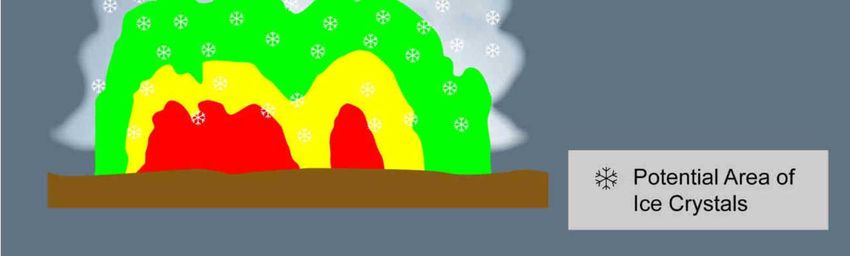
Aircraft requested that it avoid adverse weather conditions due to a medium
                         degree of shaking. Tokyo Control approved it and requested a report when
                         the Aircraft had flown through the adverse weather area.
      09:37:42           The pointer of the AOAIRS*5 2 started to fluctuate wildly.
      09:37:53           The pointer of the CAS*6 started to fluctuate wildly two seconds after the
                         pointer of the AOAIRS 2 stopped vibrating. The ECAM* 7 displayed the
                         message “NAV ADR DISAGREE*8.”
      09:37:55           Auto Pilot (AP) and Auto Thrust (AT) were automatically turned off. After
                         three seconds, the Captain voluntarily disconnected AP.
      09:38:03           The Aircraft requested descent, and Tokyo Control instructed the Aircraft to
                         descend to FL350. The Aircraft further requested descent to FL250 due to
                         “Unreliable airspeed,” which was approved. AP and AT were turned off. It
                         was indicated that the altitude of the Aircraft temporarily increased. At this
                         time, the difference in altitude readings between the altimeter and integrated
                         secondary flight display system recorded on the FDR reached 800 ft.
      09:39:36           The Aircraft requested direct flight to BUNGU, which was approved.
                         The thrust leveler was set to the CLIMB position.
      09:45:50           The Aircraft reported to Tokyo Control that it might have encountered heavy
                         icing at around FL370 and that airspeed indication could not be read
                         temporarily, which then recovered.

*5 “AOAIRS” is the AOA (angle of attack) data directly detected by the AOA probe, corrected by adding data from
  the inertia reference unit that acquires location information. When the CAS reading is 60 kt or less, AOAIRS
  becomes NCD (non-computed data). See footnote 6 for the description of CAS.
*6 “CAS” stands for Computed Airspeed. It indicates speed data in kt from ADR 1 or ADR 2. See footnote 25 for the
  description of ADR.
*7 “ECAM” stands for Electronic Centralized Aircraft Monitoring. Located in the middle of the instrument panel in
  the cockpit, this equipment provides flight crewmembers with visual information on aircraft system conditions,
  failures, check lists or operating conditions.
*8 See 2.9.4 for the description of “NAV ADR DISAGREE.”

                                                       -3-
Narita International
Place of serious incident Airport
FL370 N34°01’45”E137°11’20”
09:37:53(JST)
Fukuoka
Airport
Red dotted line: Flight route in
the flight plan
White triangle: Waypoint
Figure 1: Estimated flight route
2.1.2 Statements of Flight Crewmembers
(1) The Captain
Since the weather at Narita Airport was becoming worse, extra fuel*9 was added to the
Aircraft in addition to the fuel quantity in the flight plan. The Captain told the passengers
that shaking might start in about 40 minutes after departure from Fukuoka Airport.
When the Aircraft was cruising at FL370, green and intermittent yellow belt-shaped
echoes appeared on the on-board radar. Therefore, the Aircraft was flown approximately
20nm north of the route specified in the flight plan when it reached 80nm before (west of)
SDATI (waypoint). When the Aircraft was abeam ISEBI, the sound of rain hitting the
airframe was heard. The SAT (static air temperature) at that time was -44°C. Immediately
after that, the Co-Pilot said that the airspeed indication on the PFD on the Co-Pilot's side
was not normal. The airspeed indication pointer on the Co-Pilot's side fluctuated up and
down widely. When the airspeed indication on the PFD on the Captain's side was checked,
the airspeed indication pointer also fluctuated up and down widely. When the airspeed
indication on the Co-Pilot's side was checked again, a flag appeared, indicating a airspeed
indication failure. The Captain turned off AP and AT, and flew the Aircraft while keeping
the pitch attitude angle between 2.5° and 5.0° so as to prevent the Aircraft from stalling.
The stall warning was not appeared.
The ECAM displayed the message “NAV ADR DISAGREE.” The PFD indicated that the
flight control computer had transitioned to the Alternate Law*10.
The Aircraft asked the ATC*11 for descent. Because the airspeed indication on the
*9 “Extra fuel” refers to the fuel to be added based on the decision of the Captain and/or flight dispatcher. It is
sometimes added when a change in weather conditions at the destination or alternative aerodrome is expected.
*10 See 2.9.5 for the description of “Alternate Law.”
*11 “ATC” stands for Air Traffic Control. Although it is a general term, it refers to the Kanto South B sector of the
-4-Captain's and Co-Pilot's sides returned to normal soon after the Aircraft started descent,
the Captain turned on AT and AP were started again manually. The Captain visually
checked the main wing and ice indicator, but there was no icing.
When the Aircraft descended to FL250, the Captain explained the incident to the cabin
attendants, and continued flight to the destination.
(2) The Co-Pilot
The Co-Pilot thought that the Aircraft was flying through clouds. The echos on the
on-board radar were green. Although slight shaking continued, the Co-Pilot did not feel
anything unusual. The Co-Pilot noticed unstable airspeed indication when a sound as if
rain were hitting the front window of the cabin was heard when the Aircraft was near
abeam ISEBI. Feeling strange about the rain sound at such a high altitude, the presence of
Ice crystals*12 crossed the Co-Pilot's mind.
Soon after the Aircraft started decent, the Captain said that the airspeed indication had
returned to normal. When the airspeed indication on the Co-Pilot's side and that on the
integrated secondary flight display system were checked, the readings seemed to be
normal.
The ALL mode*13 was selected for the on-board radar during flight.
2.2 Damage to Person
There were no injuries.
2.3 Damage to the Aircraft
There was no damage to the Aircraft.
2.4 Flight Crewmembers Information
(1) Captain Male, Age 43
Airline transport pilot certificate (Airplane) December 20, 2013
Type rating for Airbus A320 May 7, 2012
Class 1 aviation medical certificate
Validity February 9, 2017
Total flight time 7,184 hr and 25 min
Flight time in the last 30 days 64 hr and 46 min
Flight time on the type of aircraft 2,997 hr and 56 min
Flight time in the last 30 days 64 hr and 46 min
(2) Co-pilot Male, Age 35
Commercial pilot certificate (Airplane) August 13, 2009
Tokyo Area Control Center.
*12 See 2.9.2 for the description of “Ice crystals.”
*13 See 2.9.6.4 for the description of “ALL mode.”
-5-Type rating for Airbus A320 January 9, 2015
Instrument flight certificate March 12, 2010
Class 1 aviation medical certificate
Validity October 13, 2016
Total flight time 3,151 hr and 38 min
Flight time in the last 30 days 81 hr and 42 min
Flight time on the type of aircraft 1,355 hr and 27 min
Flight time in the last 30 days 81 hr and 42 min
2.5 Aircraft Information
2.5.1 Aircraft
Type Airbus A320-232
Serial number 5245
Date of manufacture August 6, 2012
Certificate of airworthiness
Validity : From July 17, 2016 to July 30, 2017
Category of airworthiness Airplane Transport T
Total flight time 9,938 hr and 39 min
Flight time since the last periodic inspection 1,897 hr and 31 min
(2C Heavy Maintenance on October 26, 2015)
(See Appended Figure 1 “Three-View Drawing of Airbus A320-232”)
2.5.2 Weight and Balance
When the serious incident occurred, the Aircraft’s weight is estimated to have been 134,600
lbs and the position of the center of gravity is estimated to have been 33.6% MAC*14, both of which
are highly probable to have been within the allowable range (maximum take-off weight of 169,750
lbs, and 20.5 to 38.2% MAC corresponding to the weight at the time of the serious incident).
2.5.3 Records of Maintenance and Repair of the Aircraft
According to the maintenance records of the Aircraft, the airspeed system and static pressure
system were inspected, and no problem was found in the heavy maintenance conducted from
September to October 2015.
2.6 Meteorological Information
2.6.1 Weather Synoptic Based on Surface Analysis Chart
(1) According to the surface analysis chart released by the Japan Meteorological Agency
*14 “MAC” stands for Mean Aerodynamic Chord, meaning a chord that represents the aerodynamic characteristics
of a wing. It is the representative chord length if the chord is not constant as in the case of a sweptback wing.
33.6% MAC indicates a position located at a distance of 33.6% from the leading edge of the mean aerodynamic
chord.
-6-(JMA) on July 9, 2016 at 09:00, a front was extended from the Kanto coastal sea to the
southern part of Kyushu, and there was a low pressure with central pressure of 1,006 hPa
on the front, which was moving to the east. In addition, there was the first typhoon with a
central pressure of 985 hPa near Taiwan. (See Figure 2.)
According to the short-range forecast reference released by the JMA at 03:40 on the
same day, the low pressure was expected to pass eastern Japan via western Japan on the
night of the 9th, and reach the area above the sea east of the Kanto region in the early
hours of the 10th. Due to the influence of warm humid air attracted by the low pressure,
the state of the atmosphere was expected to become very unstable from western Japan to
eastern Japan from the 9th, causing very heavy rain mainly on the Pacific side. In western
Japan where the front would be stationary, a large amount of precipitation was expected.
Figure 2: Surface analysis chart released on July 9, 2016 at 09:00
(2) According to the domestic significant weather forecast chart for the next six hours
released by the JMA on July 9, 2016 at 03:15, significant weather areas (inside the cloud
shapes) were expected to expand to part of the Tokai region, and to the southern part of the
Kinki region and the eastern part of the Shikoku region, moving to the east at a speed of 15
kt. Along with this, a medium air turbulence and icing, rain, thunderbolts, and cumulus
clouds, including cumulonimbus clouds, with a cloudiness of around 5/8 to 7/8 (BKN*15)
were expected. (See Figure 3.)
The Captain obtained this significant weather forecast chart from the flight dispatcher
*15 “BKN” refers to the cloudiness of 5/8 to 7/8 in reporting the apparent ratio of the area covered by clouds to the
entire sky.
-7-in the briefing at the time of the departure from Narita International Airport for the first
flight on the day of the serious incident.
Figure 3: Domestic significant weather forecast chart released on July 9, 2016 at 03:15
2.6.2 Radar Observatory Data
(1) Echo intensity
According to the echo intensity*16 chart provided by the JMA (hereinafter referred to as
“the echo intensity chart”), there was a narrow echo area with a very strong intensity that
corresponds to a rainfall of 80 mm/h or more at directly south of the area near the place of
the serious incident at 9:40 (JST). In addition, there were wide echo areas that correspond
to a rainfall of 16 to 24 mm/h and 24 to 32 mm/h on the south side of the ocean off the
Tokaido region. (See Figure 4 Composite chart of echo intensity chart and estimated flight
path.)
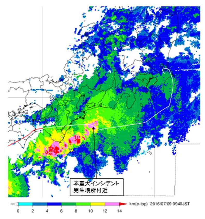
(2) Echo peak altitude
According to the echo peak altitude*17 chart provided by the JMA (hereinafter referred
*16 “Echo intensity” refers to the displayed intensity of a precipitation area which is obtained by converting to the
amount of precipitation the radio echo reflected from clouds that contain moisture to the JMA's weather radar
on the ground.
*17 “Echo peak altitude” refers to the maximum altitude of a radar echo that is displayed based on radar
-8-to as “the echo peak altitude chart”), there was an echo with a peak altitude of 12 to 14
km (39,370 to 45,931 ft) at directly south of the area near the place of the serious incident
at 9:40 (JST). (See Figure 5 Composite chart of echo peak altitude chart and estimated
flight path.)
Approximate place of the Approximate place of the
serious incident serious incident
Figure 4: Composite chart of echo Figure 5: Composite chart of echo
intensity chart and estimated peak altitude chart and estimated
flight path flight path
2.7 Flight Recorder Information
The Aircraft was equipped with U.S. Honeywell's FDR which can retain approximately 25
hours of data and U.S. L3 Communications' CVR*18 which can retain approximately 2 hours of
data. The Aircraft continued flight without unloading the FDR and CVR after the serious incident
occurred. Although the FDR retained the records when the serious incident occurred, the records on
the CVR were overwritten and erased. To complement the records on the FDR, data recorded on the
QAR was also utilized.
The time data in FDR was calibrated by correcting the time signals in the ATC
communication records with the VHF transmission keying signals in FDR.
With regard to CAS, it is not recorded whether ADR 1 or ADR 2 data was recorded.
2.8 Information on Tests and Researches
2.8.1 Maintenance record of the Pitot Tubes
In a heavy maintenance work conducted from September to October 2015, an insulation
resistance test (hereinafter referred to as the "IR test") of the three pitot tubes equipped on the
Aircraft (No. 1 for the Captain, No. 2 for the Co-Pilot and No. 3 for the integrated standby
instrument system) was conducted in accordance with the maintenance manual, and it was
confirmed that the test results in all measurement points were within the specification. There is no
observation by the JMA.
*18 “CVR” stands for Cockpit Voice Recorder.
-9-record of pitot tube replacement after the heavy maintenance.
No fault was found in the preflight inspection of the Aircraft on the day of serious incident. No
damage was found on the three pitot tubes in the visual inspection after the arrival at Narita
International Airport.
2.8.2 Tests of the pitot Tubes
In order to check the function of the three pitot tubes equipped on the Aircraft, test (IR test,
power consumption test, and leak test) were conducted at the manufacturer of the pitot tubes from
August 24 to 25, 2016. On pitot tube No. 2, bending was found in the incoming inspection and the IR
test result was below the specification. No fault was found on pitot tubes No. 1 and No. 3.
2.9 Additional Information
2.9.1 Icing
The first half of the 2016 issue of AIM-j*19 (supervised by the Civil Aviation Bureau, Ministry
of Land, Infrastructure, Transport and Tourism and the Japan Meteorological Agency (Chapter 8)
June 20, 2016) states as follows:
856. SEVERE ICING e. Ice Crystal icing
High density ice crystals may be observed in the vicinity of convective weather areas that are
accompanied by an active cumulonimbus. Ice crystals hardly ever accumulate over cold surfaces of
the airframe, however, engine blades may be damaged, or abnormal vibrations are experienced by
the ice crystals peeled off and collided with the second stage of the compressor after being
accumulated on the engine compressor. Additionally, loss of power or flameout may be caused by
sublimation of the ice crystals.
Ice crystals are generally not displayed on the airborne radar since they are in a form of fine
particles, however, the high density ice crystals have been observed above and in the vicinity of
intense rainfall area. A pilot is strongly suggested avoid any area which has moderate or strong
echoes below (closer to icing altitudes), even if no echoes are observed at the flying altitude.
2.9.2 Information on Ice Crystals
2.9.2.1 Information from the Manufacturer
The Flight Crew Techniques Manual (hereinafter referred to as “the FCTM*20”) from the
manufacturer states as follows. (See Figures 6-1 to 6-3; refer to the FCTM provided to the
Company). The revised FCTM that includes content related to ice crystals was provided to the
Company on March 22, 2017, which was after the serious incident occurred. Before this revision,
content focused on imparting knowledge about information on ice crystals had not been handled in
the internal training at the Company.
*19 “AIM-j” stands for Aeronautical Information Manual Japan, which provides basic information needed for flying
primarily in Japanese airspace, general flight procedures, and ATC procedures. It also provides basic
information on weather, explanation of factors that affect flight safety, references that may be helpful for daily
flight operations, and explanation of terms related to air traffic control.
*20 “FCTM” refers to a manual that supplements FCOM to provide pilots with practical information on how to
operate the same aircraft model.
- 10 -GENERAL
Clouds are made of particles of water that can be either liquid or solid. Ice crystals are very small
solid water particles. In some areas, there may be a very high concentration of ice crystals that may
have adverse effect on the aircraft.
Areas of ice crystals are usually next to, or above the core of convective clouds that have
high-intensity precipitation. However, areas of ice crystals may sometimes even be several nautical
miles away from the core of the associated convective cloud.
When ice crystals get in contact with a hot surface, they melt. Depending on the type of surface, a
water film may appear. On the windshield, this water film creates not-expected appearance of “rain”
at temperatures too low for liquid water to exist.
If there is a specific airflow towards a zone of the aircraft where water can build up, accretion may
occur and create a block of ice. This is why flight in areas of ice crystals may result in various effects,
for example engine vibrations, engine power loss, engine damage, or icing of air data probes.
Isolated Continental Thunderstorm
- 11 -DETECTION OF ICE CRYSTALS
Ice crystals are difficult to detect with the weather radar, because their reflectivity is very low due
to both their small size and solid state. In addition, in areas of ice crystals, the flight crew should
not expect significant icing of the airframe. This is because ice crystals bounce off cold aircraft
surfaces. This is why even the ice detection system does not detect ice crystals, because ice crystals
do not build up on ice detectors and visual ice indicators.
However, areas of ice crystals are usually associated with visible moisture. Ice crystals can be
indicated by one or more of the following:
‐ Appearance of rain on the windshield at temperatures too low for rain to exist. This “rain” is
usually associated with a “Shhhh” noise
‐ Small accumulation of ice particles on wipers
‐ Smell of ozone or Saint Elmo’s fire
‐ Aircraft TAT indication that remains near 0 °C (due to freezing of the TAT probe)
‐ Light to moderate turbulence in IMC at high altitude
‐ No significant radar echo at high aircraft altitude, combined with:
• High-intensity precipitation that appears below the aircraft, or
• Aircraft position downwind of a very active convective cloud.
Mesoscale Convective Cloud
OPERATIONAL RECOMMENDATIONS FOR ICE CRYSTALS
If possible, the flight crew should avoid flight into areas that have a high concentration of ice
crystals. The following recommendations apply:
‐ Use the water radar:
• Identify areas that have a strong echo, and perform a detailed analysis of the structure of the
convective clouds
• If necessary, use the weather radar manual modes for a more precise analysis
• Pay particular attention to strong echoes below the aircraft and to downwind areas.
‐ To avoid convective clouds, comply with operational recommendations (Refer to AS-WXR
Operations in Convective Weather), particularly:
• Prefer lateral to vertical avoidance
- 12 -• Comply with the avoidance margins
• Deviate upwind instead of downwind.
If the aircraft encounters ice crystals precipitation despite avoidance action, and if this results in
engines or probes misbehaviors, the published procedures and recommendations apply, and in
particular:
‐ ECAM alerts related to engine failure or engine stall
‐ ECAM alerts related to probe failure
‐ QRH procedures such as the ones linked to unreliable airspeed indication, engine vibrations,
engine relight in flight…
2.9.2.2 Information from the Federal Aviation Administration
The AC21 (AC91-74B Pilot Guide: Flight in Icing Conditions) from the Federal Aviation
Administration (hereinafter referred to as “the FAA”) states on convective weather and icing as
follows:
2-4. CONVECTIVE WEATHER AND ICE CRYSTALS.
a. Convective Weather Systems.
Convective weather systems, especially those associated with tropical weather fronts, can pump
large quantities of moisture to high altitudes that freezes into ice crystals that can remain aloft.
These ice crystals can remain as a cloud well after the convective system has decayed. Clouds and
temperatures less than 10 °C are better indicators of the possible presence of ice crystals when near
convective weather.
b. Hazards.
Above flight level (FL) 250, clouds contain little liquid water and mostly contain ice particles. These
clouds with no liquid water have about 20 times less radar reflectivity than rain drops, and
therefore are difficult to detect. Airborne weather radar will receive little to no returns at these
altitudes unless it is tilted down to lower altitudes near or below the freezing level. Strong returns
from the lower altitudes indicate the possibility of hail, severe turbulence, or large quantities of ice
crystals that could be encountered above and accrete inside turbine engines when overflying these
areas. Large deposits may ultimately result in engine upset, engine damage from ice shedding,
power loss, or engine shutdown.
(Omission)
3-11. EFFECTS OF ICING ON CRITICAL SYSTEMS.
a. Pitot Tube.
The pitot tube is particularly vulnerable to icing because even light icing can block the entry hole of
the pitot tube where ram air enters the system. This will affect the airspeed indicator and is the
reason most airplanes are equipped with a pitot heating system. The pitot heater usually consists of
coiled wire heating elements wrapped around the air entry tube. If the pitot tube becomes blocked,
and its associated drain hole remains clear, ram air no longer is able to enter the pitot system. Air
already in the system will vent through the drain hole, and the remaining will drop to ambient (i.e.,
outside) pressure. Under these circumstances, the airspeed indicator reading decreases to zero
*21 “AC” stands for Advisory Circular, which is published by the FAA to provide professionals in the aviation
industry with useful information.
- 13 -because the airspeed indicator senses no difference between ram and static air pressure. If the pitot
tube, drain hole, and static system all become blocked in flight changes in airspeed will not be
indicated, due to the trapped pressures. However, if the static system remains clear, the airspeed
indicator would display a higher than-actual airspeed as the altitude increased. As altitude is
decreased, the airspeed indicator would display a lower-than-actual airspeed.
(Omission)
c. Stall Warning Systems.
(1) Stall warning systems provide essential information to pilots. A loss of these systems can
exacerbate an already hazardous situation. These systems range from a sophisticated stall warning
vane to a simple airflow-activated stall warning switch. The stall warning vane (also called an
“AOA sensor” since it is a part of the stall warning system) has a wedge-like shape, has freedom to
rotate about a horizontal axis, and is connected to a transducer that converts the vane’s movements
into electrical signals transmitted to the airplane’s flight data computer. Normally, the vane is
heated electrically to prevent ice formation. The transducer is also heated to prevent moisture from
condensing on it when the vane heater is operating. If the vane collects ice, it may send erroneous
signals to such equipment as stick shakers or stall warning devices. Aircraft that use a stall horn
connected to the stall warning switch may not give any indication of stall if the stall indicator
opening or switch becomes frozen.
(Omission)
f. Outside Air Temperature (OAT)/True Air Temperature (TAT) Probe.
(1) Ice crystals can clog and freeze over the heated temperature probe on some aircraft. This
tendency to freeze over appears to be sensitive to the location of the probe on the airframe. If the
OAT/TAT probe freezes over, the indicated temperature will erroneously rise to 0 ºC and hold. In
this situation, some aircraft systems will alert the flight crew that there is a disagreement between
various ambient temperature sensors, thus indicating the presence of ice crystals.
(Omission)
5-7. CRUISE.
An aircraft that is certificated for flight in icing conditions will be able to cope with most icing
encounters provided that its ice protection systems are operating properly and that the exposure is
not extended beyond their capabilities. However, if it is possible to exit the icing conditions by a
change in altitude or flight path, this is certainly advisable (see Chapter 3, paragraph 3-13). During
any icing encounter, the pilot should carefully monitor the behavior of the aircraft and know when
to activate the airplane’s anti-ice and deicing systems. Unless otherwise stated in the flight manual,
the pilot should activate pneumatic boot deicing systems at the first sign of ice accretion.
(Omission)
g. Airspeed Monitoring.
It is critical that the pilot monitor airspeed to assure that at least the minimum flight speed for the
configuration and environmental conditions is maintained. There have been events in which the
airspeed loss from cruise to stall occurred in a matter of minutes.
h. Weather Systems.
- 14 -The pilot should exercise care when operating turbine engine powered aircraft in or around
convective weather systems. Ice crystals can be accreting in the engine even though the airframe
and ice detectors may not show any indications of an icing environment. This can occur at very low
ambient temperatures and high altitudes. The pilot should activate nacelle and engine anti-ice
systems if the presence of ice crystals is suspected and follow the procedures outlined in the
aircraft’s AFM as needed.
2.9.3 Information on Unreliable airspeed indication
The FCTM provided by the manufacturer states on Unreliable airspeed indication as outlined
below:
(1) The most probable reason for erroneous airspeed and/or altitude information is an
obstruction of the pitot and/or static probes. The ADRs detect most of the failures affecting the
airspeed or altitude indications. These failures lead to lose the associated speed or altitude
indications in the cockpit and trigger the associated ECAM alerts.
(2) The "UNRELIABLE SPEED INDICATION" procedure has two objectives:
‐ To fly the aircraft,
‐ To identify and isolate the affected ADR(s).
It includes the following steps:
1. Memory items*22. (if necessary),
2. Flight path stabilization,
3. Troubleshooting and isolation,
4. Flight using pitch/thrust references
(3)IN-SERVICE EXPERIENCE OF HIGH ALTITUDE PITOT OBSTRUCTIONS
Analysis of the in-service events shows that:
‐ The majority of unreliable speed events at low altitude are permanent situations, due to
the obstruction of pitot probes by rain, severe icing, or foreign objects (refer to the table
above).
‐ At high altitude, typically above FL 250, the cases of unreliable speed situation are mostly
a temporary phenomenon: They are usually due to contamination of the pitots, by water or
ice, in particular meteorological conditions. In-service experience shows that such a
contamination typically disappears after few minutes, allowing to recover normal speed
indications.
2.9.4 NAV ADR DISAGREE Indication
The Aircraft is equipped with three ADIRUs*23. The ADR*24, which is one of the units that
constitutes an ADIRU, receives air data from the angle of attack (AOA) sensor, pitot tubes, static
*22 “Memory Items” stands for emergency procedures which are necessary for flight crews to perform immediately
in their memories.
*23 “ADIRU” stands for Air Data/Inertial Reference Unit. It integrates an ADR unit that collects air data of the
aircraft and an IR unit that collects location and other information. Information from ADIRU 1 is displayed on
the PFD and ND on the Captain's side, and information from ADIRU 2 is displayed on the PFD and ND on the
Co-Pilot's side. Information from ADIRU 3 can be displayed either on the Captain's or Co-Pilot's side as
required.
*24 “ADR” stands for Air Data Reference, which is a unit that collects the air data (airspeed information and
altitude information) of the aircraft.
- 15 -ports and TAT*25 probe. Air data from the pitot tubes and static ports are converted by the ADM*26
into electrical signals, which are sent to each ADIRU. (See Figure 7 Conceptual diagram of the
airspeed system.) ADR data from the three systems (ADR 1, ADR 2 and ADR 3) that is input to the
computer (ELAC*27) are calculated to determine the median, which is used for comparison with
ADR data to determine the correctness of each ADR datum. If determined to be correct by the
computer, that data is output to another computer that controls flight operation.
If the following event occurs, AP and AT are automatically turned off, and the caution
message “NAV ADR DISAGREE” is displayed on the ECAM.
- One of the ADRs is determined to be faulty or its data that were input to the ELAC are
determined to be incorrect, and there is disagreement between data (airspeed or AOA) from
the remaining two ADRs.
If the ADR data were incorrect only temporarily and correct data have been resumed, the
disabled AP and AT can be turned on again by the pilot.
Pitot system
Static pressure system
Electrical system
Figure 7: Conceptual diagram of the airspeed system
With regard to the relationship between ADR and PFD, ADR 1 data are displayed on the PFD
for the left seat, and ADR 2 data are displayed on the PFD for the right seat. Although ADR 3 data
are displayed on the integrated secondary flight display system, it can also be displayed on the PFD
*25 “TAT” stands for Total Air Temperature. It refers to the stagnation point temperature in a flow. In the case of
aircraft, the outside temperature is determined by converting from TAT and airspeed.
*26 “ADM” stands for Air Data Module that converts air data from the pitot tubes and static ports into electrical
signals. Those signals are sent to electronic equipment such as the ADIRU as required.
*27 “ELAC” stands for Elevator Aileron Computer, which transmits calculated pitch and roll attitude commands to
the relevant flight control servos to operate them.
- 16 -for the right or left seat by switching.
2.9.5 F/CTL ALTERNATE LAW Indication
On the Aircraft, there is a relationship called Law between input to the side-stick operated by
the PF to control the Aircraft and its response. When a failure occurs in the flight control system or
its related equipment, the computer changes the Law of the flight control system from the Normal
Law*28 to the Alternate Law or Direct Law*29 depending on the stage of the failure.
The unreliable airspeed indication that occurred on the Aircraft caused the Law of the
computer to change from the Normal Law to the Alternate Law. As a result, the protection function
to prevent stalling (high angle of attack protection) and the protection function to prevent overspeed
(high speed protection) stopped, the caution message “F/CTL ALTERNATE LAW” appeared on the
ECAM, and an amber “x” mark was displayed on the PFD. (See Figure 8 Change from Normal Law
to Alternate Law displayed on the PFD.)
Inside red circles Inside red circles
Normally, green “=” marks are Green “=” marks change to amber
displayed. “x” marks.
Figure 8: Change from Normal Law to Alternate Law displayed on the PFD
2.9.6 Aircraft System
2.9.6.1 Probe Ice Protection
The air data probes (AOA sensor, pitot tubes, static ports and TAT probe) on the Aircraft are
electrically heated to prevent icing. To ensure that reliable information is obtained from the air
*28 Under “Normal Law,” the control-related computers attempt to keep the aircraft within the predetermined limit
of flight range, and a protection function operates when the pilot has made excessive control.
*29 Under “Direct Law,” the protection function for keeping the aircraft within the limit of the flight range stops
when two or more control-related computers have failed.
- 17 -data system, the air data probes are automatically heated while at least one engine is operating.
Each air data probe is connected to each channel of the air data system. The heater system in each
channel is controlled by the probe heater computer.
2.9.6.2 Window Heat
The probe ice protection device on the front cockpit window and the defogging device on the
side windows are electrically heated. They are automatically heated while at least one engine is
operating.
2.9.6.3 Ice Indicator
The ice indicator on the Aircraft is the protruding part on
the outside of the front cockpit window, which is used by the
Captain and Co-Pilot to visually check for icing. (Refer to Photo
1 Ice indicator on the Aircraft.)
2.9.6.4 Weather Radar
The weather radar on the Aircraft sends
Photo 1: Ice Indicator on the Aircraft
short-wavelength radio waves to the front of the Aircraft.
It analyzes the reflected radio waves and constructs a three-dimensional image that shows cloud
conditions ahead of the Aircraft. The image can be displayed on the ND during flight by selecting
the relevant image display mode. The color identification of the radar echoes displayed on the ND is
related to precipitation and radar reflectivity, using green*30, yellow, and red in ascending order of
strength. There are three image display modes, as outlined below:
(1) ALL: Displays the range of 80° on the right and left, and 15° up and down with respect to
the direction of the flight route.
(2) ON PATH: Displays 80° on the right and left, and ± 4,000 ft up and down with respect to the
direction of the flight route.
(3) ELEVATION: Displays 80° on the right and left with respect to the direction of the flight
route at the selected flight altitude
2.9.7 Messages Recorded on the Aircraft
In the aircraft equipment (CFDIU*31) that records the condition of the aircraft in flight, which
is equipped in the aircraft, there are recorded two kinds of messages related to the state of the
aircraft displayed during the flight and messages related to the fault of the aircraft. Also, many of
the equipment of the Aircraft have the BITE*32 function, and can record faults and transmit fault
information to CFDIU. From the CFDIU after landing, the record related to this serious incident
*30 A “green” echo is displayed on the ND when the intensity of the reflection of the beam emitted from the Airborne
weather radar is weak with a reflectivity of 20 to 30 dBZ and rainfall is 0.7 to 4.0 mm per hour. A yellow echo is
displayed when the beam reflectivity is 30 to 40 dBZ and rainfall is 4.0 to 12.0 mm per hour. A red echo indicates
a reflectivity of 40 dBZ or more and a rainfall of 12.0 mm or more per hour.
*31 “CFDIU” is an abbreviation for Centralized Flight Data Interface and Management Unit, and refers to a device
that receives and processes various parameters of the aircraft with a digital signal or the like.
*32 “BITE” stands for Built-in Test Equipment and refers to a self-diagnostic device incorporated in equipment such
as avionics.
- 18 -was taken out as post-flight data*33. Major post flight data of the aircraft are as follows.
(1) Messages concerning faults of the aircraft
- 09: 37, Record that the signal from ADR 2 was not normal
- 09: 38, Record that the signal from ADR 1 was not normal
(2) Messages concerning the state of the aircraft
- 09: 37, Record that the message “F / CTL ALTERNATE LAW” was indicated
- 09: 37, Record that the message “NAV ADR DISAGREE” was indicated
2.9.8 Issuance of TCD(Japanese Airworthiness Directive)-5734B-2015
EASA*34 issued AD*35 to the same model in October 2014 in order to replace the part number
C16195AA type with the C16195BA type pitot tube which was enhanced anti-ice performance.
Thereafter, the outline of the content of the latest version of AD issued on October 09, 2015, which
was twice revised, is as follows.
In order to prevent the fault causing airspeed indication failure, which is caused by the pitot
tube being affected by certain weather conditions, replacement of the pitot tubes with the
C16195BA type was required; but there was no evidence that the C16195BA type pitot tube was
strong enough to withstand the ice crystals at very high altitudes. For that reason, we ask for a
change to a further improved type of pitot tube.
In response to this, the Civil Aviation Bureau issued the TCD-5734B-2015 including the same
content even in Japan.
The pitot tube of the aircraft was equipped with a pitot tube of part number type 0851HL
manufactured by UTAS Co., which further improved anti-freeze capability from the time of
manufacturing the aircraft.
2.9.9 Revised regulations for Airspeed System
In March 2015, EASA revised the design standards for the airworthiness classification
transportation type T (CS25) and for the engines (CSE), and introduced the requirement to prove
that an airspeed indicator probe functions properly under each of the newly set conditions where
Supercooled large droplets*36 exist, conditions where Supercooled large droplets and Ice crystals
exist together, as well as conditions where Ice crystals exist; but this requirement is to be applied to
aircraft that newly apply for aircraft design after March 12, 2015, and is not applied to the Aircraft.
2.9.10 Related Information
(1) As examples of the pitot tube not working properly due to the effect of the Ice crystals
causing an unreliable airspeed, there are the aviation accidents of Air France AF447 flight
off the Atlantic Ocean on June 1, 2009 and the incidents of Jetstar 12 flight off the Pacific
Ocean on October 28, 2009.
*33 “Post flight data” is a record that helps the mechanic to easily search for faults, it is recorded and indicated
only for hours and minutes, but there is no indication in seconds.
*34 “EASA” stands for European Aviation Safety Agency.
*35 “AD” is an abbreviation of Airworthiness Directive, which refers to the documents that request actions to
restore the aircraft and other vehicles to an acceptable level of safety. The AD referred to here is the one issued
by the EASA.
*36 “Supercooled large droplets” refers to water droplets that do not freeze even when water reaches 0°C, and are of somewhat
larger sizes. In addition, supercooled water droplets also cause icing.
- 19 -(2) As the response of Japanese airlines such as All Nippon Airways Co., Ltd. and Star Flyer
Inc., in light of the issuance of the AF447 flight accident report, the airlines operating the
Airbus A320 are alerting their staff with regards to Unreliable Airspeed with their own
analysis in their safety information sheets issued in-house.
3. ANALYSIS
3.1 Qualification of Flight Crew Members
Both the Captain and the Co-pilot held both valid airman competence certificate and valid
aviation medical certificate.
3.2 Aircraft Airworthiness Certificate and others
The Aircraft had a valid airworthiness certificate and had been maintained and inspected as
prescribed.
3.3 Relations to the Meteorological Conditions
As described in 2.6.1(1), it is highly probable that there was a severe rainfall phenomenon in
the area from West Japan to the Pacific Ocean side of East Japan where this serious incident
occurred, caused by warm and humid air from the south, flowing towards the front and low
pressure area. Also, as convective system became active due to the influx of warm and humid air, it
is highly probable that a cumulonimbus with echo peak altitude ranging from 12 to 14 km (from
39,370 to 45,931 ft) was generated as described in 2.6.2. Furthermore, it is highly probable that
from the forecasted significant weather described in 2.6.1 (2), that there were ordinary turbulence
and icing, rain, lightning strikes and cumulonimbus in the adverse weather area (in the clouds).
As described in 2.1.2, the Captain and Co-Pilot state that they heard the sound like as rain
drops hitting the cockpit window at -44°C, with the airborne weather radar echo in the green air
space; but in general, the limit for naturally occurring water to remain a liquid under supercooled
conditions is considered to be around -40°C. Therefore, as described in 2.9.6.2, it is somewhat likely
that the melting of ice crystals on the cockpit window, which is electrically heated to prevent icing.
In addition, as described in 2.1.2 by the Captain and Co-Pilot, as well as the information on ice
crystals in 2.9.2, as there were no traces of icing on the wings and the ice indicator of the Aircraft
after hearing the sound like as raindrops hitting the window, it is somewhat likely that the aircraft
encountered ice crystals existing near or above the center of the cumulonimbus, which formed due
to highly active growth existing in the weather front. It is probable that the temporary unreliable
airspeed indication on the Captain’s side and the Co-Pilot’s side due to icing of the No. 1 and No. 2
Pitot tubes, while encountering ice crystals.
3.4 Events Related to the Aircraft
3.4.1 Damage to No. 2 Pitot Tubes
Regarding the No. 2 Pitot tube, there was no failure after heavy maintenance as described in
2.5.3 and it was not replaced, and there was no clear record in the post-flight data described in
2.9.7, showing that it failed. Also, as described in the statement of the Captain in 2.1.2, it is
probable that the Captain was able to engage AP and AT again as the error in the ADR data
described in 2.9.4 was temporarily occurred, caused by icing of the Pitot tube. For that reason, it is
probable that when this serious incident occurred, the Pitot tube was not faulty. On the other hand,
regarding the finding of a bend in the No. 2 Pitot tube during the incoming inspection by the
- 20 -manufacturers described in 2.8.2, from the fact this damage was not found during the visual
inspection after the serious incident described in 2.8.1 occurred, it is somewhat likely that the
damage occurred when the Pitot tube was sent to the manufacturer, but it was not possible to
determine this. In addition, it was not possible to determine the relationship between the unreliable
airspeed indication and the bend of the Pitot tube.
3.4.2 Unreliable airspeed indication
As described in 2.7, as the CAS recorded on the FDR depends on data from either one of ADR1
or ADR2, normally if the data from ADR1 is invalid, it switches to data from ADR2; from the
parameters recorded on the FDR and QAR (refer to Appended Figure 2), the statements of the
Captain and the Co-Pilot described in 2.1.2, as well as the post flight data described in 2.9.7, the
following analysis can be made regarding the passing of time and airspeed indication.
(1) From 09:37:42 to 09:37:53
According to QAR, AOAIRS2 was recorded as the NCD. From this, it is probable that up
until this point, the CAS data of ADR2 was below 60kt. Meanwhile, since CAS did not
fluctuate greatly, it is highly probable that CAS was data from ADR 1, and that the CAS
data of ADR 1 was normal. Also, as described in 2.9.4, it is highly probable that the ELAC
data temporarily gave an error due to the signal input from ADR 2 deviating far from the
median value.
(2) From 09:37:53 to 09:38:21
It was recorded that the CAS was fluctuating in an extremely short period in the range
of 260kt to 50kt in about 28 seconds, from 09:37:53 to 09:38:21. Regarding this, it is highly
probable that the CAS data of ADR1, which was normal during this time, fluctuated,
leading to the airspeed indicator on the Captain's side and the Co-Pilot's side, and flags
appearing. Also, as described in 2.9.4, it is highly probable that NAV ADR DISAGREE was
displayed because the data from ADR 2 was erroneous and the airspeeds of ADR 1 and
ADR 3 became inconsistent.
According to FDR, AT and AP were automatically canceled at around 09:37:55, however
the Captain voluntarily disconnected the AP at around 09:37:58. It is probable that this
procedure was taken in recollection of the procedure corresponding to the unreliable
airspeed indication. As described in 2.9.3, QRH describes the relationship between the
aircraft attitude that should be used as a reference, and the engine output relative to the
weight of the aircraft when the Unreliable airspeed indication occurs. As the statement of
the Captain described in 2.1.2, the pitch attitude angle was set to near 2.5°in recollection of
the procedure corresponding to the unreliable airspeed indication, and the engine output
set to the CLIMB position, to continue to fly the aircraft safely in consideration of the day’s
weather conditions. After that, it is probable that the Unreliable airspeed indication was
resolved in a short period of time.
(3) From 09:38:21 to 09:38:33
Since the AOA data recorded in the FDR greatly fluctuates and the AOAIRS1 data
recorded in the QAR as the NCD, it is highly probable that the CAS data from ADR 1 was
less than 60kt during this time. On the other hand, it is highly probable that the CAS data
recorded in the FDR switched from ADR1 to ADR2, since the fluctuation of the CAS
recorded in the FDR stopped.
(4) After 09:38:33
- 21 -You can also read