All Products Guide Vol.5 - Yokogawa Test & Measurement
←
→
Page content transcription
If your browser does not render page correctly, please read the page content below
All
Products
Guide
           Vol.5   Precision
                   Making

                      Catalog YMI130-EN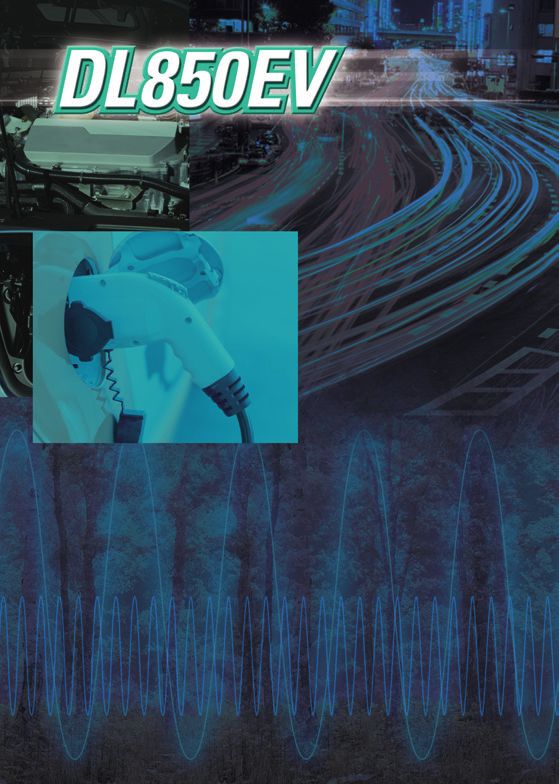
Main Products Line up

 Oscilloscopes                                                                 Digital Power Analyzer

                                                                                                             Precision Power Analyzer
                                                                                                             WT3000E

                                                                                                         Precision Power Scope
  ScopeCorder               High-Speed Data Acquisition Unit                                             PX8000
  DL850E/DL850EV            SL1000

                                                                                                             Precision Power Analyzer
                                                                                                             WT1800

                                                                                                                            new

  Mixed Signal
  Oscilloscopes                  Mixed Signal Oscilloscopes
  DLM2000 Series                 DLM4000 Series
                                                                            Power Analyzer              Digital Power Meters
                                                                            WT500                       WT300E Series

 Generators, Sources, Manometers etc.                    Optical Measuring Instruments
                                                                 new
                          DC Voltage /
                          Current Source
                          GS200

                                                  Optical Spectrum          Optical Wavelength Meter     Multi Application Test
                                                  Analyzer                  AQ6150 Series                System
                                                  AQ6370 Series                                          AQ2200 Series
                          AC Voltage
                          Current Standard
                          2558A

                                                   Optical Time Domain          Optical Loss Test Set       Multi Field Tester
                          Precision DC
                                                   Reflectmeter                 AQ1100                      OTDR
                          Calibrator
                                                   AQ7280                                                   AQ1200 Series
                          2553A

                   new

                                                                                                                   Handy size
                          Precision DC                                                                             Optical Power Meter
                          Calibrator                                                                               / Light Source
                          2560A
                                                   1G/10G Ethernet Tester       AQ2170       AQ2180     AQ4280
                                                   AQ1300 Series                Series       Series     Series
Calibrator

                               new

           CA700                      CA310      CA320        CA330                 CA150                 CA71                   CA450

       Digital Multimeter                                                Insulation Tester

                                                                         MY40               MY10 Series      2406E Series    3213A Series
 TY700 Series   TY500 Series    732 Series       73101

       Illuminance Meter                       Earth Tester                         Clamp-on Tester

                                                                                CL150/155                         300          CL420
           510 Series                              EY200                                         CL220           Series

       Thermometer                      Meters Products                                              Clamp-on Power Meter

                                                                                                 new

    TM20        TX10 Series           201314               204102          205206                           CW500                    CW10

Internet Website
                   http://tmi.yokogawa.com                                           Precision Measuring Instruments
                                      The Yokogawa website offers
                                      not only product and technical
                                      information but also campaign
                                      information, user registration,
                                      document download, free
                                      software download, e-mail
                                      news subscription, catalog
                                      request, price inquiry, and lots
                                      of other content.                                     279301                          276910
Contents
      [Oscilloscopes]                                                                                                                  P. 6 ~ P. 21

      ScopeCorder and High-Speed Data Acquisition                      Mixed Signal Oscilloscope
       Unit Selection Guide.....................................6       (DLM2000 Series)................................. 16, 17
      ScopeCorder (DL850E/DL850EV)...................8                 Mixed Signal Oscilloscopes (DLM4000)..... 18, 19
      ScopeCorder Accessories....................... 10, 11            Waveform Measuring
      High-Speed Data Acquisition Unit (SL1000)..... 12                 (Oscilloscopes Accessories).......................20
      High-Speed Data Acquisition Unit                                 Oscilloscope Application Software
       (SL1000 Acquisition Software).................... 13             (Xviewer/MATLAB tool kit)...........................21
      Digital and Mixed Signal Oscilloscopes
       Selection Guide........................................... 14
      Common Features of DL/DLM Series............ 15

      [Digital Power Analyzers]                                                                                                        P. 22 ~ P. 35

      Digital Power Analyzers Selection Guide.......22                 Current Sensor Unit (751522 / 751524).........32
      Power Analyzer (WT500)...............................23          WT Series Accessory Software (760122 and Power
      Precision Power Analyzer (WT3000E).....24, 25                     Consumption Measurement Software)............33
      High Performance Power Analyzer                                  WT Series Accessory Software
       (WT1800)..............................................26, 27     (761922 IEC regulation software)................34
      Digital Power Meters (WT300E)..............28, 29                Digital Power Analyzers Accessories List
                                                                        (Accessories List)........................................35
      Precision Power Scope (PX8000)............30, 31
      AC/DC Current Sensor
       (CT60/CT200/CT1000)................................32
      Current Probe (751552).................................32

      [Generators, Sources, Manometers etc.]                                                                                           P. 36 ~ P. 47

      DC Voltage/ Current Source (GS200)............36                 Digital Resistance Meter (7556)....................44
      Multi Channel Source Measure Unit (GS820)....37                  Temperature Measuring Instrument (7563)....44
      Source Measure Unit (GS610)......................38              Arbitrary/Function Generator (FG400 Series)....45
      GS Series Accessory Software (765670 Curve                       Pressure Standard (MC100)..........................46
       Tracer Software for the GS series)..............39              Manometers (MT210/MT210F/MT220/MT10)....47
      Precision DC Calibrator (2553A)....................40
      AC Voltage Current Standard (2558A)...........41
      Precision DC Calibrator (2560A)....................42
      Digital Multimeter (DM7560)..........................43

      [Optical Measuring Instruments]                                                                                                  P. 48 ~ P. 59

      Optical Spectrum Analyzer (AQ6370 Series)....48                  AQ2170 Optical Power Meter........................56
      Optical Spectrum Analyzer (AQ6370D).........49                   AQ2180 Optical Power Meter........................56
      Optical Spectrum Analyzer                                        AQ4280 Optical Light Source........................56
       (AQ6375B/AQ6376 )...................................50          MFT-OLTS (AQ1100).....................................57
      Optical Spectrum Analyzer (AQ6373B).........51                   MFT-1/10GbE (AQ1300 Series).....................58
      Optical Wavelength Meter (AQ6150 series)......52                 Remote OTDR (AQ7277)...............................59
      Multi Application Test System (AQ2200)........53
      Optical Time Domain Reflectmeter (AQ7280)....54
      MFT-OTDR (AQ1200)....................................55
Oscilloscopes
[Calibrator]                                                                          P. 60 ~ P. 65

CA700, CA150, CA51/CA71, CA310, CA320, CA330, CA310, CA320, CA330, CA450, CW500

                                                                                                             Digital Power
                                                                                                               Analyzers
[Clamp-on Power Meter]                                                                    P. 66

                                                                                                           Manometers etc.
                                                                                                             Generators,
                                                                                                              Sources,
CW10

                                                                                                             Optical Measuring
[Digital Multimeter]

                                                                                                               Instruments
                                                                                      P. 68 ~ P. 71

TY700 Series, TY500 Series, 732 Series, 73101, 96095

                                                                                                                Calibrator
[Clamp-on Tester]                                                                     P. 72 ~ P. 73

CL100 Series, CL200 Series, 30031A/30032A, CL300 Series, CL400 Series

                                                                                                             Power Meter
                                                                                                              Clamp-on
[Insulation Tester]                                                                   P. 74 ~ P. 77

MY40, 2406E Series, MY10 Series, 3213A Series

                                                                                                                Digital Multimeter
[Earth Tester, Other Products]                                                            P. 78

                                                                                                                Clamp-on Tester
EY200, 322610, 510 Series

                                                                                                                Insulation Tester
[Thermometer]                                                                             P. 79

TM20, TX10 Series

                                                                                                             Other Products
                                                                                                              Earth Tester,

[Precision Measuring Instruments]                                                         P. 80

2792A Series, 278610/278620, 2769, 279301/279303, 2755
                                                                                                                Thermometer

[Meters Products]                                                                         P. 81

Portable Instruments 2011 to 2053
                                                                                                           Instruments
                                                                                                            Measuring
                                                                                                             Precision
                                                                                                                Meters Products

                                       Products with this mark conform to the EMC standards (regulations
                                       on electromagnetic interference) of European Community.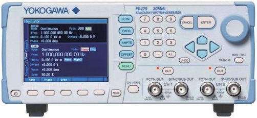
Oscilloscopes
    Oscilloscopes

                            Waveform Measuring                  ScopeCorder and High-Speed Data Acquisition Unit Selection Guide (*1)
                          hey can be used to capture single-shot or infrequently recurring signals.
                         T
  Digital Power

                         They can also execute computations on repetitive waveforms, and automatically extract waveform parameters.
    Analyzers

                                                             Model                                   DL850E/DL850EV                                                      High-Speed Data Acquisition Unit SL1000
Manometers etc.
  Generators,
   Sources,

                          Item                                                                                                                 …P8                                                                               …P12
                          Features                                   • Powerful mobile data acquisition recorders                                     • Fast Acquisition, Transfer, and Storage
                                                                     • Measure & analyze dynamic behavior of electromechanical systems                • High-Performance Data Acquisition Unit
                                                                     • Flexible modular inputs for voltage, current, sensors, CAN/LIN bus and SENT.   • Easy to use
                                                                     • Trend & Trigger on electrical power calculations (optional)                        Easy to use Standard Acquisition Software
                                                                                                                                                      • Max 128 ch Synchronized (16 ch x 8 units)
  Optical Measuring

                                                                                                                                                         Data files recorded my multiple units, in synchronized mode, are all linked
    Instruments

                                                                                                                                                         together by a common LINK file, thereby facilitating batch processing.
                          Max. sampling rate                                                            100 MS/s (*2)                                                                   100 MS/s (*2)
                          Bandwidth                                                                      20 MHz (*2)                                                                     20 MHz (*2)
                          Number of analog input channels                           128 ch max (when using eight 720220 modules)                                      16 ch max (when using any 2 ch input module.)
                          Logic input                                              128 bits max (when using eight 720230 modules)                                                            —
                          Max. vertical sensitivity (1:1)                                               100 μV/div (*2)                                                                100 μV/div (*2)
                          Vertial axis resolution                                                         16 bit (*2)                                                                     16 bit (*2)
    Calibrator

                          Max. sweep sensitivity                                                        100 ns/div (*2)                                                           15 ns/div (Zoom display)
                          Max. record length          St’d                            250 Mpts (MW) max / 10 Mpts (MW) (16 ch)                                                50 MW/ch (Single Trigger Mode)
                                                      Optional                         2 Gpts (GW) max / 100 Mpts (MW) (16 ch)                                                               —
                          Internal media drive        St’d                                       SD memory card slot                                                                         —
                          Internal HDD                Optional                       Internal 500 GB or external HDD (selectable)                                                     Internal 500 GB
  Power Meter

                          Interface                   St’d                                  USB2.0/ Ethernet (1000BASE-T)                                                                 USB2.0
   Clamp-on

                                                      Optional                                              GPIB                                                                  Ethernet (1000BASE-T)
                          Internal printer                                                      112 mm width (optional)                                                                      —
                          Others                      Optional       • 19 types of plug-in modules       • Real time math function                    • 12 types of plug-in modules
                                                                     • IRIG interface                    • Probe power (4-output)                     • Probe power (4-output)
                                                                     • GPS interface                     • Power math function                        • Without Xviewer
                                                                     • User-defined math function        • DC 12V Power drive (DL850EV only)          • With the Xviewer Math Edition (1 license) (701992-GP01)
    Digital Multimeter

                          Display (TFT LCD)                                                          10.4-inch color XGA                                                     (PC-based Acquisition Software)
                          External dimensions W × H × D (mm)                                          355 × 259 × 180                                                                 319 × 154 × 350
                          Weight (kg)                                                                  Approx. 6.5 (*3)                                                                Approx. 6.0 (*3)
                         *1: See each product catalog for more detaled specifications       *2: Depends on input module     *3: Plug-in modules are not included
    Clamp-on Tester
    Insulation Tester
  Other Products
   Earth Tester,
    Thermometer
Instruments
 Measuring
  Precision
    Meters Products

                                                                                                                               6
Oscilloscopes
Oscilloscopes
Plug-in Module Selection Guide*1
Maximum
Model Number of
Input Sample rate Resolution Bandwidth Isolation input voltage DC accuracy Note
Digital Power
No. channels
Analyzers
(DC+ACpeak)
1000 V*2
720211*9 100 MS/s 12-Bit 20 MHz 2 Isolated 200 V*3 ±0.5% High speed · High voltage · Isolated
701250 600 V*2
*5 10 MS/s 12-Bit 3 MHz 2 Isolated ±0.5% high noise immunity
200 V*3
600 V*2 High sensitivity range (1 mV/div), low noise
701251 1 MS/s 16-Bit 300 kHz 2 Isolated ±0.25%
140 V*3 (±100 µVtyp.), and high noise immunity
Manometers etc.
Analog 600 V*2 4 CH BNC input low noise,
Generators,
720254 1 MS/s 16-Bit 300 kHz 4 Isolated ±0.25%
Sources,
Voltage 200 V*3 high noise immunity
701255*5 600 V*4
10 MS/s 12-Bit 3 MHz 2 Non-Isolated ±0.5% non-isolation version of model 701250
200 V*3
701267 100 kS/s 16-Bit 40 kHz 2 Isolated 850 V*10 ±0.25% with RMS, and high noise immunity
Isolated
720220 200 kS/s 16-Bit 5 kHz 16 (GND-terminal) 42 V *3 ±0.3% 16 CH voltage measurement (Scan-type)
non-isolated (CH-CH)
Optical Measuring
100 kS/s (Voltage), 16-Bit (Voltage), 40 kHz (Voltage), ±0.25% thermocouple (K, E, J, T, L, U, N, R, S, B, W,
Instruments
701261 2 Isolated 42 V
500 S/s (Temperature) 0.1°C (Temperature) 100 Hz (Temperature) (Voltage) iron-doped gold/chromel)
701262 100 kS/s (Voltage), 16-Bit (Voltage), 40 kHz (Voltage), ±0.25% thermocouple (K, E, J, T, L, U, N, R, S, B, W,
2 Isolated 42 V
500 S/s (Temperature) 0.1°C (Temperature) 100 Hz (Temperature) (Voltage) iron-doped gold/chromel), with AAF
Analog
Voltage thermocouple (K, E, J, T, L, U, N, R, S, B, W,
& 701265 500 S/s (Voltage), 16-Bit (Voltage), ±0.08 iron-doped gold/chromel), high sensitivity
100 Hz 2 Isolated 42 V
Tempera- 500 S/s (Temperature) 0.1°C (Temperature) (Voltage) range (0.1 mV/div), and low noise
ture (±4 µVtyp.)
16-CH voltage or temperature measure-
±0.15% ment (scan method)
Calibrator
720221*8 10 S/s 16-Bit 600 Hz 16 Isolated 42 V (Voltage) Thermocouple (K, E, J, T, L, U, N, R, S, B,
W, Au-Fe-chromel)
±0.5% (Strain) Supports strain NDIS, 2, 5, 10 V built-in
701270 100 kS/s 16-Bit 20 kHz 2 Isolated 10 V bridge power supply
Strain
±0.5% (Strain) Supports strain DSUB, 2, 5, 10 V built-in
701271 100 kS/s 16-Bit 20 kHz 2 Isolated 10 V bridge power supply, and shunt CAL
Analog ±0.25% (Voltage) built-in anti-aliasing filter, Supports built-in
Voltage, 701275 100 kS/s 16-Bit 40 kHz 2 Isolated 42 V ±0.5%
Power Meter
(Acceleration) amp type acceleration sensors (4 mA/22 V)
Clamp-on
Acceleration
Measurement frequency of 0.01 Hz to
420 V*2 ±0.1% 500 kHz, Measured parameters (frequency,
Frequency 701281 1 MS/s 16-Bit resolution 625 ps 2 Isolated
42 V*3 (Frequency) rpm, period, duty, power supply frequency,
distance, speed)
depend on
8-bit × 2 (8-bit/port) × 2, compatible with four-type of
Logic 720230 10 MS/s — — non-isolated logic probe —
ports logic probe (sold separately)
used.
Digital Multimeter
CAN Data of max. 32-bit allowable
CAN 720240 100 kS/s — — (60signals × 2) It is available for DL850EV only. Max. two
Isolated 10 V —
port (2) modules can be installed in a main
unit.*6 *7
CAN port × 1, LIN port × 1
(60signals × 2) 10 V (CAN port)
CAN, LIN 720241 100 kS/s — — Isolated — Available for DL850EV only, up to 2
port 18 V (LIN port) modules*6 *7
Supported protocol: SAE J2716. It is
11 data × 2
SENT 720243 100 kS/s — — Isolated 42 V — available for DL850EV only. Max. four (4)
Clamp-on Tester
ports modules can be installed in a main unit.*6 *7
*1: Probes are not included with any modules. *2: In combination with 700929, 702902 or 701947 probe. *3: Direct input *4: In combination with 10:1 probe model 701940
*5: Some of the models 701250/701255 shipped on or before July, 2007 may require factory rework. *6: Any other modules can be installed in the remaining slots.
*7: U
p to four CAN Bus Monitor Modules (720240), CAN & LIN Bus Monitor Modules (720241) or SENT Monitor Module (720243) in total can be used on a single main unit. For the CAN Bus Monitor Modules (720240) and CAN & LIN Bus
Monitor Modules (720241), up to two in total can be used on a single main unit. *8: The 16-CH Scanner Box (701953) is required for measurement.
*9: Class 1 Laser Product, IEC60825-1:2007 *10: In combination with 758933 and 701954.
Insulation Tester
Compatibility of the plug-in modules with the main units.
Plug-in Module Main Unit
Model Name DL850E DL850EV SL1000
701250 High-speed 10 MS/s 12-Bit Isolation Module available available available
701251 High-speed 1 MS/s 16-Bit Isolation Module available available available
Other Products
Earth Tester,
701255 High-speed 10 MS/s 12-Bit non-Isolation Module available available available
701261 Universal Module available available available
701262 Universal Module (with Anti-Aliasing Filter) available available available
701265 Temperature/high-precision voltage Module available available available
701267 High-voltage 100 kS/s 16-Bit Isolation Module (with RMS) available available available
701270 Strain Module (NDIS) available available available
Thermometer
701271 Strain Module (DSUB, Shunt-CAL) available available available
701275 Acceleration/Voltage Module (with Anti-Aliasing Filter) available available available
701281 Frequency Module available available available
720211 High-speed 100 MS/s 12-Bit Isolation Module available available available
720220 16 CH Voltage Input Module available available NA
720221 16 CH Temperature/Voltage Input Module available available NA
Instruments
Measuring
Precision
720230 Logic Input Module available available NA
720240 CAN Bus Monitor Module NA available NA
720241 CAN & LIN Bus Monitor Module NA available NA
720243 SENT Monitor Module NA available NA
720254 4 CH 1 MS/s 16-Bit Isolation Module available available NA
Meters Products
* Probes are not included with any modules.
*U p to four CAN Bus Monitor Modules (720240), CAN & LIN Bus Monitor Modules (720241) or SENT Monitor Module (720243) in total can be used on a single
main unit. For the CAN Bus Monitor Modules (720240) and CAN & LIN Bus Monitor Modules (720241), up to two in total can be used on a single main unit.
These modules are available for the DL850EV only.
* The use of a 720221 module always requires the External Scanner Box (model 701953).
7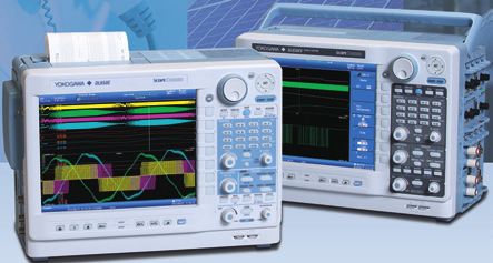
Oscilloscopes
Oscilloscopes
ScopeCorder DL850E/DL850EV
Powerful data acquisition enables the research of dynamic
Digital Power
Analyzers
behavior within your application
Overview
Manometers etc.
Generators,
Sources,
A ScopeCorder is a powerful portable data acquisition
recorder that can capture and analyze both
transient events and trends up to 200 days. Using
flexible modular inputs it combines the measurements
Optical Measuring
of electrical and physical (sensor) signals, such as from
Instruments
CAN, LIN, SENT and is also able to trigger on electrical
power related calculations in real-time.
DL850EV
DL850E Flexible Inputs with Built-in Signal Conditioning
Choose from up to 19 input modules and gain a thorough insight into any
Calibrator
application by synchronizing the measurement of multiple parameters.
• Voltage and Current
• Sensor Outputs
• Temperature, Vibration
Basic Specifications /Acceleration, Strain,
Power Meter
Frequency
Clamp-on
Max. sampling rate 100 MS/s (720211)(*1) • Logic Signals & CAN / LIN
Frequency bandwidth 20 MHz (720211)(*1) and SENT
Number of channels Max. 128 ch,
Number of slots for the plug-in module: 8 arge (2 GPoint) memory offers long duration measure-
L
Digital Multimeter
Logic input Max. 128 bits ment and two instantaneous zoom locations
(When using eight 720230 modules) – 2 GPoint memory (/M2 option) –
A/D conversion resolution 16 or 12 bits (1*) Comes standard with 250 MPoints of memory, expandable with 1 or 2 GPoint
DC accuracy ±(0.5% of 10 div) options.
Large capacity memory does not only simply provide longer durations of
(701250 and 701255)(*1)
measurement, but also higher sampling rate at the same measurement time
Time axis setting 100 ns/div to 20-day/div
Clamp-on Tester
or multi-channel at the same sampling rate.
Time axis accuracy ±0.005%
Max. record length Standard 10 Mpts (MW)/ch, total 250 Mpts Zoom to 2 locations
(MW) (with /M2 option) instantaneously
100 Mpts (MW)/ch, total 2 Gpts (GW)
Channel-to-channel Definable math waveforms 8
Insulation Tester
calculation function Main screen:
Instantly zooms 1
second (100 ms/div) even
Automatic measurement Maximum number of measured parameters 32 20 days of recording
(2 days/div)
when the main screen is
displaying 20 days of
of waveform parameters Up to
recording (2 days/div)
Cycle statistical/historic process
Maximum number of cycles 64,000 2 million times!
Zoom screen: Long memory does not guarantee
Maximum number of parameters 64,000 1 hour (12 min/div) better efficiency if the memory
& handling and display engine is slow.
Internal media drive SD memory card slot (standard) 1 second (100 ms/div) Our faster than ever GIGAZoom 2
Other Products
Earth Tester,
Engine instantaneously zooms into
500 GB internal hard drive (option) two locations.
External hard drive can be connected (option)
Communication interface USB 2.0 (standard)/1000BASE-T Ethernet (standard)
GP-IB (option) ong duration, continuous saving of waveforms
L
Built-in printer(option) 112-mm width, A6 thermal printer – Hard disk recording (/HD0, /HD1 option) –
Measured data can be streamed directly to a built-in 500 GB hard disk (/HD1
Thermometer
Other options IRIG interface
option)*1 or through the external HDD interface (/HD0 option)*1. With long
GPS interface periods of evaluation testing, measurements can be
User defined computation performed at 100 kS/s on 16 channels simultaneously for 10 hours*2.
Real time math computation
*1 The /HD0 and /HD1 options cannot be specified together.
Power math computation *2 It depends on the external hard disk connected when using the /HD0 option.
Four probe power outputs
Instruments
Measuring
Precision
DC 12 V power drive (DL850EV only)
Display 10.4-inch TFT color LCD monitor
Display resolution 1024 × 768 pixels (XGA)
External dimensions 355 (W) × 259 (H) × 180 (D) mm 100 kS/sec
(excluding handle and protrusions) with 16 ch
Meters Products
Weight Approx. 6.5 kg to 9 kg (varies depending on simultaneously
the types and the number of modules used)
(*1): Varies depending on the module.
8
Oscilloscopes
Oscilloscopes
ontinuous data recording for durability test and/or
C
surveillance test
Intuitive, user-friendly acquisition software comes standard. Continuous
data recording into a PC Hard Disk Drive(HDD) can be performed by “free-
Digital Power
Analyzers
run mode” with no restriction of recording time and file size. The Wizard
automatically recognizes any connected DL850E and its’ plug-in modules.
Just click the Start button to start measuring right away--no complicated VEHICLE EDITION
settings to enter.
DL850E ACQ Software Enhanced capabilities for vehicle design and
development such as CAN, LIN buses and SENT monitoring
Manometers etc.
Generators,
Sources,
The ScopeCorder Vehicle Edition is designed for engineers working in the automotive and railway industry.
A common measurement challenge is to combine measurements of electrical signals, physical
performance parameters indicated by sensors, together with CAN bus, LIN bus or SENT data transmitted by
Ethernet or USB the powertrain management system. A ScopeCorder Vehicle Edition addresses this challenge by combining
the measurement of all signals to provide thorough insight into the dynamic behavior of the
Optical Measuring
electromechanical system. The result is a considerable time saving compared to other approaches such as
Instruments
PC-Internal
HDD analysis on PC or other software.
[Example of comparison and verification of a measured signal
DL850E (front-end) and CAN bus signal]
ime synchronization for accurate measurements
T Measurement by a module other
Calibrator
– GPS interface (/C30 option) – than the CAN Bus Monitor Module
A GPS antenna can be directly connected to the DL850E side panel. The Physical signal input (analog voltage, command pulse)
DL850E time clock and the sampling clock can be adjusted accordingly.
1 frame output (CAN only)
GPS satellite Data frame input (Data or remote frame)
Power Meter
GPS antenna CAN bus
Clamp-on
I/O in CAN Bus
Monitor Module
ECU Module Sensor 1 Sensor 2
Note: There is a certain restriction when using the 720240, 720241 and/or 720243
modules together with the /G5 option. Please contact our sales representative.
Note: This option can be provided only for a nation that is not prohibited by the Radio Law.
Digital Multimeter
rend waveform monitor for power and harmonic param-
T Support for both AC and DC power
(/DC option, DL850EV only)
eters in real time – /G5 option –
Max. 126-type power parameter can be calculated. The calculation nLow power consumption • Can be driven by external DC power
such as the vehicle’s battery
results of these parameters can be displayed in DL850E screen as trend of 60 - 120 VA (typ.)
12 V DC (10 – 18 V)
Clamp-on Tester
waveforms in real time. The raw signal waveforms along with calculated
nLow noise compared to
parameters(waveforms) can be displayed as trend waveforms with maximum using an external • Can also be driven by AC power.
data updating rate of 100 kS/s. inverter 100 V AC (100 – 120 V)
Trend waveforms of each orders of harmonics, bar-graphs and vector 200 V AC (200 – 240 V)
displays can be displayed.
Model Number and Suffix Codes
Insulation Tester
Models and Suffix Codes
Model Suffix Codes Description
DL850E DL850E main unit, 250 MPts(W) memory*1
DL850EV DL850EV main unit, 250 MPts(W) memory*1
-D UL and CSA standard
-F VDE standard Other Products
Earth Tester,
[ Power parameter trend display example ] [ Harmonic analysis example ] Power -R AS standard
Cord -Q BS standard
-H GB standard
Once the “Analysis” key is pressed -N NBR standard
on the front panel, the dedicated set- -HE English menu and panel
-HJ Japanese menu and panel
up menu will appear on the screen
-HC Chinese menu and panel
which enables to setup easily. -HK Korean menu and panel
Thermometer
Languages
-HG German menu and panel
-HF French menu and panel
For example, 6-input(3-voltage and 3-current) waveforms for 2-line, which are -HL Italian menu and panel
-HS Spanish menu and panel
total 12 raw signal waveforms, can be monitored simultaneously along with
/B5 Built-in printer (112 mm)*5
max. 126-parameter/1-line (or 54-parameters/2- line) can be calculated. /DC DC12 V power (10-18 V DC) (can be specified for DL850EV only)*5
/M1 Memory expansion to 1 GPts(W)*2
Inverter Inverter/Motor Testing /M2 Memory expansion to 2 GPts(W)*2
Instruments
Measuring
Precision
Motor Torque/ Load /HD0 External HDD interface*3
Inverter section rotation
Input sensor /HD1 Internal HDD (500 GB)*3
Converter section Drive circuit Options /C1 GP-IB interface*4
/C20 IRIG and GP-IB interface*4
Convert AC to DC signals /C30 GPS interface*4, *7
Modulate DC signal and convert to any AC signals /G2 User-defined math function
/G3 Real time math function*6
Meters Products
3-Voltage and 3-Current /G5 Power math function (with including Real time math function)*6
/P4 Four probe power outputs
3-Voltage and 3-Current *1: The main unit is not supplied with a plug-in module.
DL850E /G5 *2, *3, *4, *5, and *6: When selecting these, specify one of them.
*7: The /C30 option can be provided only for a nation that is not prohibited by the Radio Law.
9
Oscilloscopes
    Oscilloscopes

                                                                                Waveform Measuring             ScopeCorder Accessories
                                                Product                               Model No.                                     Description*1
  Digital Power
    Analyzers

                                                                                                       DC to 15 MHz, 1/10-1/100 selector switch, max. allowable differential
                         Differential Probe                                             700925
                                                                                                       voltage ±500 V (DC + ACpeak)

                                                                                                       DC to 100 MHz, 1/100-1/1000 selector switch, max. allowable differential
                         Differential Probe                                             700924
                                                                                                       voltage ±1400 V (DC + ACpeak) or 1000 Vrms (1/1000 range)
Manometers etc.
  Generators,
   Sources,

                         Current Probe                                                  701917         5 Arms, DC to 50 MHz, High-sensitivity

                         Current Probe                                                  701933         30 Arms, DC to 50 MHz, supports probe power
  Optical Measuring
    Instruments

                         Current Probe                                                  701930         150 Arms, DC to 10 MHz, supports probe power

                         Current Probe                                                  701931         500 Arms, DC to 2 MHz, supports probe power

                         Current Probe                                                  701932         30 Arms, DC to 100 MHz, supports probe power
    Calibrator

                         Probe Power Supply                                             701934         Supply (4 outputs), large current output, external probe power

                         10:1 Probe (for Isolated BNC Input)                            700929         1000 Vpk-CAT II
  Power Meter
   Clamp-on

                         10:1 Probe (wide temperature range, for
                                                                                        702902         -40 to +85°C, DC to 60 MHz, 1000 Vpk-CAT II
                         isolated BNC input)

                         1:1 Safety BNC Adapter Lead
                                                                                        701901         1000 Vrms-CAT II
    Digital Multimeter

                         (in combination with followings)

                                 Safety mini-clip (Hook type)                         B9852MM          1000 Vrms-CAT III, black

                                 Safety mini-clip (Hook type)                         B9852MN          1000 Vrms-CAT III, red
    Clamp-on Tester

                                 Large Alligator-Clips (Dolphin type)                   701954         1000 Vrms-CAT II, 1 set each of red and black

                         Passive Probe (10:1)*2                                         701940         Non-isolated 600 Vpk
    Insulation Tester

                         1:1 BNC-Alligator Cable                                        366926         Non-isolated 42 V or less, 1 m

                         *1: Actual allowable voltage is the lower of the voltages specified for the main unit, probe and cable.
                         *2: 42 V is safe when using the 701940 with an isolated type BNC input.
  Other Products
   Earth Tester,
    Thermometer
Instruments
 Measuring
  Precision
    Meters Products

                                                                                                                           10
Oscilloscopes
Oscilloscopes
Accessories Combinations
Digital Power
Analyzers
Passive Probe for
SL1400/DL750
701940
Isolation probe Plug on clip
High-speed 100 MS/s 700929 701948
12-Bit Isolation Module Acceleration/Voltage
720211 Module (with AAF)
701275 BNC cable
Manometers etc.
1 m: 366924
2 m: 366925
Generators,
Sources,
Isolation probe
701947
Long Test Clips
701906
BNC-alligator cable
366926
High-speed 10 MS/s
Optical Measuring
12-bit Isolation Module
Instruments
701250
10:1 Passive Probe 4 mm Conversion Adapter
702902 B8099NL/ ±500 V, 15 MHz
Large Alligator Clips High-speed 10 MS/s 12-bit
B8099NM Differential Probe
(Dolphin Type) Non-isolation Module
701954 701255 700925
±1400 V, 100 MHz
Calibrator
Differential Probe
High-speed 1 MS/s 1:1 Safety BNC Warning:
700924
16-bit Isolation Module Adapter Lead Connect the probe earth
701251 701901 Safety mini clips cable to ground (grounding
(Hook Type) potential) when using these
B9852MM/B9852MN differential probes with
isolation modules.
7000 Vpk, 50 MHz
Differential Probe
701926
Power Meter
Clamp-on
Measurement Lead Set
758933
Alligator Adapters
758922
High-Voltage 100 kS/s
16-Bit Isolation Module
701267
Digital Multimeter
Safety BNC Cable 1:1 Banana-alligator Cable
1 m : 701902 Universal Module 366961
3 m : 701903 Alligator Adapters
758929 701261
Frequency Module
701281
Clamp-on Tester
Current Probe 30 Arms
DC-50 MHz Fork Terminal Adapters
701933 758921
Universal Module Shunt Resister for 4-20 mA Measurement
(with AAF) 250 Ω ± 0.1% : 438920
701262 100 Ω ± 0.1% : 438921
10 Ω ± 0.1% : 438922
Insulation Tester
Current Probe
4CH 1 MS/s 150 Arms DC-10 MHz /P4, Probe Power
16-bit Isolation Module 701930 4-output (option)
720254
Temperature/High-precision
Voltage Module
701265
Current Probe
Other Products
Earth Tester,
500 Arms DC-2 MHz Probe Power
701931 4-output
701934
High-speed Logic Probe
700986
Current Probe
Thermometer
5 Arms DC-50 MHz
701917
Isolated Logic Probe
700987
Logic input
Module
720230 Logic Probe
(TTL level/Contact Input)
Bridge Head (NDIS) 1 m: 702911
120 Ω: 701955 3 m: 702912
350 Ω: 701956
Instruments
Measuring
Precision
Strain Module (NDIS)
701270
Scanner Box
701953
(Provided with a connecting cable)
Bridge Head Note:
(DSUB, Shunt-Cal) This unit is always required for
Meters Products
120 Ω: 701957 measurement.
350 Ω: 701958
Strain Module 16 CH Temp./Voltage
(DSUB Shunt-CAL) Input Module
701271 720221
11Oscilloscopes
Oscilloscopes
High-Speed Data Acquisition Unit SL1000
Fast Acquisition, Transfer, and Storage
Digital Power
Analyzers
High-Performance Data Acquisition Unit
Easy to use
Manometers etc.
– Easy to use Standard Acquisition Software
Generators,
Sources,
Max 128 ch Synchronized (16 ch x 8 units)
– Data files recorded by multiple units, in synchronized mode, are all linked
together by a common LINK file, thereby facilitating batch processing.
Using this LINK file, data from all units can be processed and analyzed, as
one, at the same time.
Optical Measuring
Instruments
SL1000
Ethernet/USB
Basic Specifications
Calibrator
Plug & Play: Auto-recognition of units and modules
Input type: Plug-in module SYNC SYNC
(A/D converters built in to each unit) IN OUT
Maximum number of input channels:
16 (One unit operation) Unit 0 Unit 1 Unit 2 Unit 7
128 (8 units synchronous operation) Waveform Waveform Waveform Waveform
file file file file
Maximum sample rate: 100 MS/s on all channels
Power Meter
Measuring mode: Free Run and Triggered
Clamp-on
Clock source: Internal and external
Maximum record length (internal memory): Unit 1-7
In Free Run mode 1 module: 32 MW/ch Data link
2 modules: 16 MW/ch file
3 to 4 modules: 8 MW/ch
5 to 8 modules: 4 MW/ch Stand-Alone Recording
Digital Multimeter
In Single Trigger mode 1 module: 50 MW/ch – Normally, SL1000 is controlled by PCs. However, SL1000 can record data
2 modules: 25 MW/ch even without PCs (/HD1 option is required).
3 to 4 modules: 10 MW/ch This stand-alone recording function is useful for the measurement in the
5 to 8 modules: 5 MW/ch
Measuring groups: Up to 4 groups definable with independent sample rates severe environment.
Trigger mode: Normal, Single, and Single(N)
Trigger source: Input channel, External, LINE , Time
Record conditions: Model Number and Suffix Codes
Clamp-on Tester
For Free Run mode Immediate, abs. time, time divided, alarm, and external trigger
For Trigger mode Each trigger Model Suffix Code Description
Internal hard disk: 500 GB (with the /HD1 option)
SL1000 High-Speed Data Acquisition Unit*1
Maximum real-time hard disk recording speed: 720120
Including Xviewer Standard Edition (1 license)(701992-SP01)
Internal hard disk 1.6 MS/s
-D UL and CSA standard
(= 200 kS/s × 8 ch = 100 kS/s × 16 ch)
-F VDE standard
Power cord -R AS standard
Insulation Tester
-Q BS standard
Maximum measuring time (unit: sec) at Single triggered measurement
-H GB standard (Complied with CCC)
/HD1 Internal 500 GB HDD
Number of Measuring Channels
/C10 Ethernet Interface
2 ch 4 ch 8 ch 16 ch
Options /P4 Probe power (4-output)
100 MS/s 0.5 0.25 0.1 0.05
/XV0 Without Xviewer
50 MS/s 1 0.5 0.2 0.1
/XV1 With the Xviewer Math Edition (1 license)(701992-GP01)
Sampling rate 10 MS/s 2.5 1.25 0.5 0.25
Other Products
Earth Tester,
1 MS/s 25 12.5 5 2.5 *1: Plug-in modules and PC not included with the SL1000.
500 kS/s 100 50 20 10
200 kS/s 250 125 50 25 Model Description
1 kS/s 50000 25000 10000 5000 720211 High-speed 100 MS/s 12-Bit Isolation Module (2 ch)
701250 High-speed 10 MS/s 12-Bit Isolation Module (2 ch)
701251 High-speed 1 MS/s 16-Bit Isolation Module (2 ch)
701255 High-speed 10 MS/s 12-Bit non-Isolation Module (2 ch)
Features
Thermometer
701267 High-voltage 100 kS/s 16-Bit Isolation Module (with RMS, 2 ch)
701261 Universal Module (2 ch)
Fast Acquisition
701262 Universal Module (with Anti-Aliasing Fileter, 2 ch)
–U p to 100 MS/s on all channels (10 ns sampling interval)
701265 Temparature / High-precision voltage Module (2 ch)
–S upports parallel testing: Perform measurements with up to four simulta- 701275 Acceleration / Volatage Module (with Anti-Aliasing Filter 2 ch)
neously independent sample rates 701270 Strain Module (NDIS, 2 ch)
Fast Transfer and Storage 701271 Strain Module (DSUB, Shunt-CAL, 2 ch)
–S tream data to PC via high speed USB 2.0 or 1000BASE-T Gigabit Ether-
Instruments
701281 Frequency Module
Measuring
Precision
net
–S tream data to a PC hard disk or the SL1000's internal hard disk in real Product Model No. Description
time (at speeds of 1.6 MS/s = 100 kS/s × 16 ch)1 720901-01 For SL1000 (1 m)
– Maximum 8 synchronized units Synchronized connection cable
720901-02 For SL1000 (3 m)
1: Speed depends on PC performance and measuring conditions. 751541-E4 EIA standard
Rack mounting kit
751541-J4 JIS standard
Meters Products
12Oscilloscopes
Oscilloscopes
High-Speed Data Acquisition Unit SL1000 Acquisition Software
Intuitive Operation
Easy to Use
Digital Power
Analyzers
Setup Wizard Makes It Easy
The four screens of the Setup Wizard guide you easily through detailed settings
for configuring the system, measuring, saving, and displaying. You can save and
recall your settings at any time.
Manometers etc.
Setup Wizard
Generators,
Sources,
Optical Measuring
Start
Instruments
measurement
Control Buttons––Just Like Your DVD Remote
Measurement and saving can be started and stopped using the same familiar
buttons found on a DVD remote control. Start using the instrument on the same
day you receive it, with absolutely no programming required.
Calibrator
Main Specifications of Acquisition Software
Plug and Play Auto-recognition of units and modules
Measurement modes Free Run and Triggered
ACQ modes Normal, envelope, and box average
Power Meter
Clamp-on
Clock sources Internal and external
Measurement groups Up to 4 groups definable with independent sample rates
Trigger modes Normal, single, and single(N)
Displaying X-Y Waveforms
Trigger sources CH1-CH16, LINE, Time, and External
Other trigger functions Combination trigger, hold-off, pretriggers, and trigger delay You can view both T-Y waveform display and X-Y waveform display. Using its fast
Save conditions Manual operation, or based on time, or alarms update feature, you can evaluate data quickly and easily.
Other save functions Manual save (file division), specify no. of saves, save all data
Digital Multimeter
in memory, and save simultaneously to PC’s hard disk and
SL1000’s internal hard disk (with /HD1 option)
Save format Binary data file (original, *.wdf)
Waveform data Binary data file(s) can be converted to ASCII
conversion (Xviewer) (*.csv) or Excel (*.xls) format
Maximum speed for saving in real time
PC hard disk 1.6 MS/s (= 100 kS/s × 16 channels)*1
Waveform monitor Trend display (displays measured waveforms of different
sample rates simultaneously)*2, and instantaneous value
Clamp-on Tester
displays (digital, bar graph, meter, and thermometer)
X-Y display X-axis channel settings, selection of main or zoomed
waveform (in Triggered mode), and selection of the number of
data points to draw (2 K, 10 K, 100 K)
Mark display (Free run mode) Setting of marks (up to 128 marks, each mark can display up to
16 characters), display color setting, mark editing, deletion of
marks, mark list, collectively saving mark data with the same file
Accumulating Waveforms
Insulation Tester
name as the waveform data, and loading mark data into Xviewer.
Accumulation display Accumulates T-Y and X-Y waveforms
Snapshot Waveform that is currently being displayed can be retained on Using the accumulation feature, you easily view unevenness of repetitive data.
the screen as a snapshot waveform. Display color setting and
snapshot waveform deletion
Display groups Up to 4 display groups
Other display functions History waveform, arbitrary axis divisions, and horizontal axis
scaling + specifiable units (external clock)
Waveform analysis Cursor and parameter measurement*3 Other Products
Earth Tester,
Offline waveform computation (with /XV1 option)
Max. Number of displayed waveforms (CHs)
10 waveforms (Math1 to Math 10)
Operations +, -, ×, /, trigonometry, differentiation/integration, FFT, and others
Alarms Channel (alarm display and alarm history analysis)*4, system
alarm, and alarm output
GO/NO-GO determination*3 Waveform parameter judgment and judgment output
System requirements
Thermometer
OS Windows XP (SP2 or later) /Windows 7 (32 bit /64 bit) /
Windows 8 (32 bit /64 bit)
CPU Core 2 Duo 2 GHz or better
Memory 1 GB or more
Hard disk 500 MB or more of free space (40 GB or more when using the
auto-save function)
Communication interfaces USB 2.0/Ethernet 1000BASE-T (with /C10 option) Setting Marks
Display XGA or better, Color: 65536 colors or better
You can enter comments in the Mark area when monitoring over long periods of
Instruments
Other CD-ROM drive and mouse
Measuring
Precision
time (Free Run mode).
*1: Typical values. Actual values depend on PC performance and measurement conditions.
*2: When the measurement mode is Free Run, the trigger mode is Single(N), and the number of
measurements is Infinite, there may be a limit to the number of channels that can be trend-
displayed during measurement.
*3: Triggered measurement
*4: Free Run measurement
Meters Products
For details on 701992 Xviewer, see page 21.
13Oscilloscopes
Oscilloscopes
Waveform Measuring Digital and Mixed Signal Oscilloscopes Selection Guide
The DLM series digital oscilloscopes
Digital Power
have high-speed sampling and a
Analyzers
wide range of bandwidths that
can be utilized for design and
development of electronic devices.
They can also execute computations
on repetitive waveforms and
Manometers etc.
automatically extract waveform
Generators,
Sources,
parameters.
The DLM series offers an extensive
selection of digital oscilloscopes
with large-capacity memories,
powerful triggering functions,
Optical Measuring
unique History Memory function
Instruments
and built-in printers. It also can save
and load data to and from internal or
external media.
Calibrator
Model
DLM2000 Series ...P16 DLM4000 Series ...P18
Item
Power Meter
Clamp-on
Features Compact & lightweight Analog 8 ch+Logic 16bits/Analog 7 ch+Logic 24bits
Analog 4 ch/Analog 3 ch+Logic 8bits Long memory
Long memory UART,I2C,SPI,CAN,CAN FD,LIN,FlexRay and SENT bus
UART,I2C,SPI,CAN,CAN FD,LIN,FlexRay and SENT bus analysis functions
analysis functions Power supply analysis functions
Power supply analysis functions Large display
Digital Multimeter
Max. sampling rate 2.5 GS/s 2.5 GS/s
Bandwidth 500 MHz(*2) 500 MHz(*2)
DLM2022,DLM2032,DLM2052:2
Number of analog input channels 8
DLM2024,DLM2034,DLM2054:4
St’d DLM2024, DLM2034, 8 bits
Logic input
Optional DLM2054: St’d 8 bits 24 bits
Clamp-on Tester
Max. vertical sensitivity (1:1) 2 mV/div 2 mV/div
Vertial axis resolution 8 bits 8 bits
Max. sweep sensitivity 1 ns/div 1 ns/div
St’d 62.5 Mpoints 12.5 Mpoints
Max. record length
Optional 250 Mpoints 250 Mpoints
Insulation Tester
St’d Approx. 300 MB Approx. 1.8 GB
Internal storage
Optional Approx. 7.2 GB Approx. 7.2 GB
St’d USB USB/Ethernet
Interface
Optional Ethernet/GP-IB GP-IB
Built-in printer Optional 112 mm width 112 mm width
Other Products
Earth Tester,
Others Optional I2C bus analysis I2C bus analysis
SPI bus analysis SPI bus analysis
CAN, CAN FD and LIN bus analysis CAN, CAN FD and LIN bus analysis
FlexRay bus analysis FlexRay bus analysis
SENT bus analysis SENT bus analysis
UART bus analysis UART bus analysis
Probe Power Probe Power
Power supply analysis functions Power Supply analysis functions
Thermometer
User-defined math functions User-defined math functions
Display (TFT LCD) 8.4-inch color, XGA 12.1-inch color XGA
External dimensions
226 × 293 × 193 426 × 266 × 178
W × H × D (mm)
Weight (kg) Approx. 4.2 Approx. 6.6
Instruments
*1: See each product catalog for more detaled specifications.
Measuring
Precision
*2: Depends on model
Meters Products
14Oscilloscopes
Oscilloscopes
Common Features of DL/DLM Series
Multichannel Connection with a PC
Digital Power
Analyzers
This feature meets the need to measure as many signals To facilitate the use of a PC, various interfaces such
as possible simultaneously with one oscilloscope. as USB, Ethernet, and GP-IB are available as standard
DLM2000/DLM4000 series or an option.
The DLM2000 (DLM4000) series usually functions as 4 (8) In addition, various software is available to support
channel analog, and is able to switch CH 4 (8) of analog input to remote control, file transfer, and data processing
Manometers etc.
Generators,
on a PC.
Sources,
8-bit logic quickly whenever the need arises.
USB memory and peripheral devices, such as keyboard
and mouse, can be connected, and connecting to a PC
using a USB cable enables it to be used as the external
storage of the PC.
Optical Measuring
Instruments
1000BASE-T/100BASE-TX
compliant adapters
(hubs and routers)
Analog Logic Sends waveform, screen, and settings data
Remote control
Sends waveform, screen,
Mail transmission (GO/NO-GO action) and settings data
Remote control
Ethernet
(/C10 and /C11 options) USB (standard on rear panel)
DLM4000 series
Up to 8 channels of analog signals can be measured.
Calibrator
Internal storage (/C9 option)
USB memory USB keyboard
Built-in Printer
Power Meter
Clamp-on
ScopeCorder Series is available for customers that With a small built-in printer, measured waveforms can
require more channels for measurement (see page 6). be printed to paper immediately.
The DL850E supports up to 128 channel measurement.
Digital Multimeter
Long Memory
When the sample rate is increased with oscilloscopes
with less memory, the observation time may run out.
All of Yokogawa’s oscilloscope models are equipped
Clamp-on Tester
with large capacity memory. For example, the DLM2000/
DLM4000 offers long memory of up to 250 Mpoints for
measurement. A Variety of Triggers and Analysis Functions
Even at a fast sample rate of 1.25 GS/s, waveforms for 0.2
seconds can be captured. • A variety of triggers capture complex waveforms
Insulation Tester
The history memory function that divides the long • Real time digital filter with optimum noise reduction
memory can redisplay past waveforms that have • Zooms into two different points simultaneously
disappeared from the screen. • Automated measurement of waveform parameters and
With the DLM2000/DLM4000 series, up to 50,000 statistical processing function
previously captured waveforms can be saved in • Frequency analysis by FFT computation
memory. •G o/No-Go function and action on trigger function to Other Products
Earth Tester,
determine abnormal waveforms and save files.
Waveform history • Analysis functions for specific applications, such as
serial bus analysis and power supply analysis
Thermometer
Instruments
Measuring
Since a large amount of data is also processed at high
Precision
speed by dedicated hardware, the long memory can be
used comfortably without sacrificing response time.
Meters Products
15Oscilloscopes
Oscilloscopes
Mixed Signal Oscilloscope DLM2000 Series
Easy-to-Use, Portrait Body, Compact, and Large Screen Personal
Digital Power
Analyzers
Mixed Signal Oscilloscope Offers Convenience with Logic Inputs
Features
Manometers etc.
Easy-to-Use & Easy-to-See
Generators,
Sources,
Easy to use. Portrait body + large screen makes display easy to
see.
We elevated the large (8.4-inch) LCD screen up into the line
of sight. Also, the portrait format saves space on the desk or
test bench. A compact personal oscilloscope designed for easy
Optical Measuring
viewing and ease of use.
Instruments
Horizontal Postion and
Calibrator
Scale Knob
DLM2000 Dedicated Zoom Keys
Four-Direction Selector
Button
Select key moves the
cursor up/down/left/right
Basic Specifications Jog Shuttle and Rotary
Knob
Power Meter
Clamp-on
Logic input connector
Analog Signal input
Input channels Analog input DLM20x2: CH1, CH2
Vertical Postion and Scale Knob Trigger Control Keys and Level Knob
DLM20x4: CH1 to CH4
(CH1 to CH3 when using logic input)
Input coupling setting AC, DC, DC50 Ω, GND Signal observation on 4 channels or more...
Input impedance Analog input 1 MΩ ±1.0%, approximately 20 pF Flexible MSO Input
50 Ω ±1.0% (VSWR 1.4 or less, DC to 500 MHz)
Digital Multimeter
Voltage axis sensitivity 1 MΩ 2 mV/div to 10 V/div (steps of 1-2-5) Four channels is not sufficient to view the functioning of digital
setting range 50 Ω 2 mV/div to 500 mV/div (steps of 1-2-5) control circuits. The DLM2000 series converts 4 channels of
Max. input voltage 1 MΩ 150 Vrms (CAT I) analog input to 8-bit logic, and functions as a 3 channel analog
50 Ω Must not exceed 5 Vrms or 10 Vpeak
Frequency characteristics (-3 dB attenuation when inputting a sinewave of amplitude ±3 div)*1*2 + 8-bit logic MSO (mixed signal oscilloscope).
DLM202x DLM203x DLM205x
1 MΩ (when using passive probe)
Clamp-on Tester
100 mV to 100 V/div DC to 200 MHz DC to 350 MHz DC to 500 MHz
20 mV to 50 mV/div DC to 150 MHz DC to 300 MHz DC to 400 MHz
50 Ω
10 mV to 500 mV/div DC to 200 MHz DC to 350 MHz DC to 500 MHz
2 mV to 5 mV/div DC to 150 MHz DC to 300 MHz DC to 400 MHz
Maximum sample rate
Real time sampling mode Interleave OFF 1.25 GS/s
Interleave ON 2.5 GS/s
Insulation Tester
Repetitive sampling mode 125 GS/s
Maximum record length 2 ch model Repeat/Single/Single Interleave:
(/M1S) 6.25 M/25 M/62.5 MPoints
4 ch model Repeat/Single/Single Interleave:
(/M1) 6.25 M/25 M/62.5 MPoints You can replay waveforms later on, so you'll never miss
4 ch model Repeat/Single/Single Interleave:
(/M2) 12.5 M/62.5 M/125 MPoints an abnormal waveform
4 ch model Repeat/Single/Single Interleave: History function
Other Products
Earth Tester,
(/M3) 25 M/125 M/250 MPoints
Logic Signal Input (4 ch model only) With the DLM2000 series, up to 50,000 previously captured
Number of inputs 8 bit (excl. 4 ch input and logic input) waveforms can be saved in the acquisition memory. With the
Maximum toggle frequency*1 Model 701988: 100 MHz History function, you can display just one or all of the previously
Model 701989: 250 MHz
Compatible probes 701988, 701989 (8 bit input) captured waveforms (history waveforms) on screen. You can
(701980, 701981 can also be used) also perform cursor measurement, computation, and other
Display 8.4-inch TFT color liquid crystal operations on history waveforms. Using the History function, you
Thermometer
display 1024 × 768 (XGA)
can analyze rarely-occurring abnormal signals.
Rated supply voltage 100 to 240 VAC
Rated supply frequency 50 Hz/60 Hz
Maximum power consumption 170 VA
External dimensions 226 (W) × 293 (H) × 193 (D) mm (when
printer cover is closed, excluding
protrusions)
Weight Approx.4.2 kg With no options
Instruments
Measuring
Precision
Operating temperature range 5°C to 40°C
Waveform history
Abnormal signal
*1 Measured under standard operating conditions after a 30-minute warm-up followed by calibration.
*2 Value in the case of repetitive phenomenon.
Meters Products
16Oscilloscopes
Oscilloscopes
Even complex waveforms can be captured Analysis Functions
Variety of triggers combining analog and logic inputs
The DLM2000 series comes with a variety of triggers ranging FlexRay/UART/CAN/CAN FD/LIN/SENT/I2C/SPI
Digital Power
from an easy and simple Edge trigger through to sophisticated Serial analysis function options
Analyzers
Enhanced and B triggers. In particular, its ability to freely A wide variety of trigger conditions can be set, such as ID/Data
combine analog and logic inputs is a great feature of this mixed trigger combinations and combinations of serial bus triggers with
signal oscilloscope equipped with a hybrid channel. normal edge triggers. Up to four busses with different types and
speeds can be analyzed simultaneously and decode display can
Edge trigger Edge be shown in real time.
Manometers etc.
Generators,
Sources,
Switching loss, power measurement, joule integral, SOA
Enhanced triggers Edge OR
analysis, and harmonic current based on EN61000-3-2
Edge (qualified) Power supply analysis option
Utilizing the long memory capability, voltage and current
Optical Measuring
Instruments
State waveforms over long cycles can be input for computation of
switching loss (V(t) X i(t)). A wide variety of switching loss
analyses are supported, including turn on/off loss calculation,
Pulse width
loss including conduction loss, and loss over long cycles (50
Hz/60 Hz). Automated measurement of power parameters for up
State width to two pairs of voltage and current waveforms, such as active
power, apparent power, power factor and so on.
Calibrator
Serial: (option) FlexRay/CAN/CAN FD/LIN/
SENT/UART/I2C/SPI
Models and Suffix Codes
: (standard) user-defined
Model Suffix code Description
TV: NTSC/PAL/SDTV/HDTV/user-defined 710105 Digital Oscilloscope DLM2022 2 ch, 200 MHz
710110*1 Mixed Signal Oscilloscope DLM2024 4 ch, 200 MHz
Power Meter
Clamp-on
710115 Digital Oscilloscope DLM2032 2 ch, 350 MHz
710120*1 Mixed Signal Oscilloscope DLM2034 4 ch, 350 MHz
B triggers A Delay B 710125
710130*1
Digital Oscilloscope DLM2052 2 ch, 500 MHz
Mixed Signal Oscilloscope DLM2054 4 ch, 500 MHz
Power cord -D UL/CSA standard
-F VDE standard
A to B(n) -Q BS standard
-R AS standard
-H GB standard
Digital Multimeter
Dual bus -N NBR standard
Language -HE English Menu and Panel
(combination trigger of 2 serial busses) -HC Chinese Menu and Panel
-HK Korean Menu and Panel
-HG German Menu and Panel
Optimum noise reduction -HF French Menu and Panel
-HL Italian Menu and Panel
Real time filters and filters based on MATH functions -HS Spanish Menu and Panel
Option /LN No switchable logic input (4 ch model only)
The DLM2000 series has two types of filters, one real time /B5 Built-in printer
Clamp-on Tester
/M1*2 (standard) Standard memory (4 ch model only)
processed at the input circuit and one based on MATH functions. During continuous measurement: 6.25 Mpoints; Single mode:
25 Mpoints (when interleave mode ON: 62.5 Mpoints)
Since the cutoff frequency can also be finely set, these filters are /M2*2 Memory expansion (4 ch model only)
During continuous measurement: 12.5 Mpoints; Single mode:
effective in rejecting unwanted signals and observing only the 62.5 Mpoints (when interleave mode ON: 125 Mpoints)
/M3*2 Memory expansion (4 ch model only)
desired signals. During continuous measurement: 25 Mpoints; Single mode:
125 Mpoints (when interleave mode ON: 250 Mpoints)
/M1S (standard) Standard memory (2 ch model only)
During continuous measurement: 6.25 Mpoints; Single mode:
Waveform zoom and search functions 25 Mpoints (when interleave mode ON: 62.5 Mpoints)
Insulation Tester
/P2*3 Probe power for 2 ch models
Zoom two locations simultaneously, zoom search and history /P4*3
/C1*4
Probe power for 4 ch models
GP-IB Interface
search /C10*4 Ethernet Interface
/C11*4 GP-IB + Ethernet Interface
Because the DLM2000 series lets you set zoom factors /C9 Internal storage (7.2 GB)
/G2*5 User defined math (4 ch model only)
independently, you can display two zoomed waveforms with /G3*5 Power supply analysis function (4 ch model only)
different time axis scales at the same time. Also, using the /G4*5
/F1*6
Power supply analysis function (includes /G2) (4 ch model only)
UART trigger and analysis (4 ch model only)
search functions, you can search the long memory and history /F2*6 I2C + SPI trigger and analysis (4 ch model only)
Other Products
Earth Tester,
/F3*6 UART + I2C + SPI trigger and analysis (4 ch model only)
memory and instantaneously find desired waveforms that meet /F4*7 CAN + LIN trigger and analysis (4 ch model only)
the search criteria. /F5*7
/F6*7
FlexRay trigger and analysis (4 ch model only)
FlexRay+CAN+LIN trigger and analysis (4 ch model only)
/F7*7 CAN+CAN FD+LIN trigger and analysis (4 ch model only)
/F8*7 FlexRay+CAN+CAN FD+LIN trigger and analysis (4 ch model only)
Can check functions with graphical help /F9
/EX22*8
SENT analysis (4 ch model only)
Attach two 701946 probes (For 2 ch, 200 MHz models)
Graphical online help /EX24*8
/EX52*9
Attach four 701946 probes (For 4 ch, 200 MHz models)
Attach two 701946 probes (For 2 ch, 350/500 MHz models)
Thermometer
You can view detailed graphical explanations of the oscilloscope's /EX54*9 Attach four 701946 probes (For 4 ch, 350/500 MHz models)
*1: Logic probes sold separately. Please order the model 701988/701989 accessory logic probes separately.
functions and operations by pressing the “?” key in the lower left *2: One of these must be selected.
*3: Specify this option when using current probes or differential probes that don't support probe interface.
of the screen. This lets you get help on functions and operations *4: Only one of these may be selected at a time.
*5: Only one of these may be selected at a time.
on screen without having to consult the user’s manual. *6: Only one of these may be selected at a time.
*7: Only one of these may be selected at a time.
*8: The 701938 probes are not included when this option is specified.
*9: The 701939 probes are not included when this option is specified.
Additional Option License for DLM2000*
Instruments
Measuring
Precision
Model Suffix code Description
709810 -G2 User defined math (4 ch model only)
-G3 Power supply analysis function (4 ch model only)
-G4 Power supply analysis function (includes G2) (4 ch model only)
-F1 UART trigger and analysis (4 ch model only)
-F2 I2C + SPI trigger and analysis (4 ch model only)
-F3 UART + I2C + SPI trigger and analysis (4 ch model only)
-F4 CAN + LIN trigger and analysis (4 ch model only)
-F5 FlexRay trigger and analysis (4 ch model only)
Meters Products
-F6 FlexRay + CAN + LIN trigger and analysis (4 ch model only)
-F7 CAN+CAN FD+LIN trigger and analysis (4 ch model only)
-F8 FlexRay+CAN+CAN FD+LIN trigger and analysis (4 ch model only)
-F9 SENT analysis (4 ch model only)
-X1 F4 -> F7/F6 -> F8 (add CAN FD)
*: Separately sold license product (customer-installable).
17Oscilloscopes
Oscilloscopes
Mixed Signal Oscilloscopes DLM4000
The world’s first eight analog channel 500 MHz oscilloscope for faster
Digital Power
Analyzers
and more advanced power electronics, automobile electronics, and
mechatronics development.
Manometers etc.
Generators,
Features
Sources,
Yokogawa’s proprietary new enhanced eight channel
oscilloscope comes with a larger display to enable
waveforms to be easily viewed and the latest functions.
Optical Measuring
Instruments
• 8
analog channels or 7 analog channels + 8-bit logic input
• O
ptional 16-bit logic input
• U
p to 2.5 GS/s
• 3
50 MHz or 500 MHz frequency bandwidth
• 1
2.1-inch large display
DLM4000 • L
arge memory of up to 250 Mpoints
• L
ight, slim, and compact design
Calibrator
Applications
8 ch Motor Control and Inverter/IPM Circuit Development
Power Meter
Clamp-on
Simultaneous multi-channel measurements are a necessity for the development of control circuits,
Intelligent Power Module (IPM), and inverter electronics, which are the key to more efficient, compact,
and reliable high-performance motors. Up to 8-channel analog waveform measurement of the DLM4000
empowers engineers in this field.
Examples
Digital Multimeter
• Simultaneous measurement of the 3-line voltage and 3-phase current of a 3-phase motor
• Simultaneous measurement of the gate control signals of 6 IGBTs within an inverter
4 ch Limitations of 4 ch Scope
Whole-system measurement is impossible due to a lack of analog input channels when, for example, measuring the overall timing of the
Clamp-on Tester
control signals, checking an error of the phase-to-phase balance between 3 phases, and simultaneously measuring the I/O signals of a motor
driver IC.
Limitations of Two Synchronized 4 ch Scopes
Eight channel measurement using two trigger-synchronized oscilloscopes is a possible solution but it does not help increase efficiency because
there are various problems. For example, the data is not reliable due to the lack of guarantee of the synchronization of two oscilloscopes.
Insulation Tester
Double the space is required and they are difficult to carry around. The different design and operations of each of the two oscilloscopes are
cumbersome. The response is slow and handling of the measurement data is tricky.
8 ch Automobile ECU and Integrated Mechatronics Device Development
Other Products
Electronic Control Unit (ECU) and controller I/O signals must be measured simultaneously at high
Earth Tester,
speed. To meet this requirement, the DLM4000 offers eight analog channels, logic measurement, and
protocol analysis (communication data decoding) functions such as UART (RS232), I2C, SPI, CAN,
CAN FD, LIN, SENT and FlexRay to help speed up the R&D process.
Examples
• Simultaneous measurement of controller I/O signals and serial bus signals
Thermometer
CAN / CAN FD / LIN /
FlexRay / SENT
• Measurement of the analog behavior of logic signals and serial bus signals
UART / I2C /SPI
4 ch Limitations of 4 ch + 16-bit MSO
Instruments
Measuring
Precision
ECUs, controllers, and driver ICs handle many I/O signals but the 4-channel + 16-bit MSO cannot measure all the signals. Furthermore, it
measures bus communication signals and digital signals using logic input so it cannot measure waveform quality and noise margin. Therefore,
it is difficult to increase stability and reliability.
Recorder Limitations of Memory Recorder
Meters Products
A memory recorder is generally suitable for long-time multi-channel measurement, but due to its low sampling rate and slow waveform
update speed, its performance is not adequate for measuring high-speed signals and communication signals of CPUs and FPGAs, or detecting
noise that causes problems or error signals.
18You can also read