Autonomous Greenhouse Gas Sampling using Multiple Robotic Boats
←
→
Page content transcription
If your browser does not render page correctly, please read the page content below
Autonomous Greenhouse Gas Sampling using
Multiple Robotic Boats

Matthew Dunbabin

Abstract Accurately quantifying total greenhouse gas emissions (e.g. methane)
from natural systems such as lakes, reservoirs and wetlands requires the spatial-
temporal measurement of both diffusive and ebullitive (bubbling) emissions. Tradi-
tional, manual, measurement techniques provide only limited localised assessment
of methane flux, often introducing significant errors when extrapolated to the whole-
of-system. In this paper, we directly address these current sampling limitations and
present a novel multiple robotic boat system configured to measure the spatiotem-
poral release of methane to atmosphere across inland waterways. The system, con-
sisting of multiple networked Autonomous Surface Vehicles (ASVs) and capable of
persistent operation, enables scientists to remotely evaluate the performance of sam-
pling and modelling algorithms for real-world process quantification over extended
periods of time. This paper provides an overview of the multi-robot sampling sys-
tem including the vehicle and gas sampling unit design. Experimental results are
shown demonstrating the system’s ability to autonomously navigate and implement
an exploratory sampling algorithm to measure methane emissions on two inland
reservoirs.

1 Introduction

Quantification of greenhouse gas emissions to atmosphere is becoming an increas-
ingly important requirement for scientists and managers to understand their total
carbon footprint. Methane in particular is a powerful greenhouse gas, approximately
21 times higher global warming potential than carbon dioxide. Water storages are
known emitters of methane to atmosphere [11]. The spatiotemporal variation of re-
lease is dependent on many environmental and biogeochemical parameters. There-

Matthew Dunbabin
Institute for Future Environments, Queensland University of Technology, 2 George Street, Brisbane
4000, Queensland, Australia, e-mail: m.dunbabin@qut.edu.au

                                                                                               1
2                                                                    Matthew Dunbabin

Fig. 1 The multi-robot Inference Robotic Adaptive Sampling System.

fore, in order to accurately quantify this greenhouse gas release requires long dura-
tion and repeat monitoring of the entire water body.
    There are two primary pathways for methane to be released from water storages;
(1) diffusion, and (2) ebullition (or bubbling). Diffusion is the most common path-
way considered due to greater consistency across a waterway. Rates of methane
ebullition represent a notoriously difficult emission pathway to quantify with highly
variable spatial and temporal changes [6]. However, the importance of bubbling
fluxes in terms of total emissions is increasingly recognised from a number of dif-
ferent globally relevant natural systems including lakes, reservoirs and wetlands.
This represents a critical challenge to current manual survey efforts to quantify spa-
tiotemporal greenhouse gas emissions and reduce the uncertainty associated with
bubbling fluxes. This is where robotics can play a significant role.
    In this work, a novel system for direct measurement of the combined diffusive
and ebullitive methane flux and an ability to persistently monitor a wide spatial area
is presented. Termed the Inference Robotic Adaptive Sampling System, it consists of
multiple (four) networked robotic boats (see Figure 1) and provides an open archi-
tecture allowing researchers to evaluate new sampling algorithms with customisable
scientific payloads on real-world processes over extended periods of time.
    The contributions presented in this paper are; (1) A novel ASV system for nav-
igating complex inland waterways, (2) a new greenhouse gas sampling system, (3)
a multi-robot sampling strategy to survey a previously unseen environment, and (4)
an experimental evaluation of the entire system on two inland water storages.
    The remainder of this paper is as follows: Section 2 provides background in-
formation. Section 3 describes the Inference system and the gas sampling system.
Section 4 describes a preliminary sampling methodology with Section 5 showing
results from two inland water storages. Finally, Section 6 draws conclusions and
discusses future research.
Autonomous Greenhouse Gas Sampling using Multiple Robotic Boats                        3

2 Related Work

Robotic platforms capable of persistent environmental monitoring offer an efficient
alternative to manual or static sensor network sampling for studying large-scale
phenomena. However, in practice most applications are short-term experiments for
validating existing models [3]. Recent cross-disciplinary research extensively used
robots to investigate assumptions around spatiotemporal homogeneity of environ-
mental processes such as toxic algal blooms in lakes [5] and methane production in
reservoirs [6]. These studies show that combined robotic persistence and spatiotem-
poral sampling can provide significant new insight into environmental processes.
However, there are challenges to achieving persistent robotic process monitoring,
particularly in the complex environments considered here. These primarily relate to
robotic platforms for persistent navigation within complex and often dynamic envi-
ronments, and the ability to adaptively coordinate multiple robots to appropriately
sample the process of interest.
    Robotic monitoring of marine and aquatic environments has received consid-
erable attention over the last two decades [3]. Whilst most studies have focused
on underwater vehicles with restricted payloads and endurance, there is now in-
creasing focus on Autonomous Surface Vehicles (ASVs) with greater endurance
and payload carrying capacity for large-scale unsupervised environmental monitor-
ing [13, 16, 12]. These systems are primarily designed for oceanographic surveys
and are not particularly suitable for relatively unexplored inland waterways with
challenging and often varying navigational requirements.
    Recently, a series of ASVs have been designed and applied on inland waterways.
Typically, these catamaran style vehicles are of sufficient size for carrying scientific
payloads for tasks such as mapping hazards above and below the waterline [4], and
water quality monitoring [1, 7]. Whilst demonstrating environmental monitoring ca-
pabilities, there is little flexibility for adding external payloads and their navigation
capabilities are generally customised to the specific environment. The provision of
a flexible, yet capable, robotic platform is a key consideration in this research.
    Navigation around narrow inland waterways is often more challenging than for
the ocean due to issues such as above, below and on-water obstacles and GPS reli-
ability (e.g. in mountainous and forested systems). A number of sensors have been
used to detect obstacles and in identifying free-space paths. Hitz et al. [7] use water
depth only for detecting shallow regions, whereas Ferreira et al. [4] and Leedekerden
et al. [9] use scanning laser range finders and sonar to produce high-resolution 3D
maps of the above and below water environment. Cameras have also been proposed
for detecting specific objects on the water [4, 2]. Scherer et al. [14] have used cam-
eras and laser scanners (albeit on an aerial robot) to map the edges of waterways and
the free-space above the water as the robot traverses them. Whilst high-resolution
sensors such as lasers and sonar can provide robust navigation capabilities, for per-
sistent monitoring their power consumption can be a particular challenge. Exploiting
lower power, and cost, sensing modalities such as vision and ultrasonics to provide
sufficient obstacle detection capabilities is a goal of this research.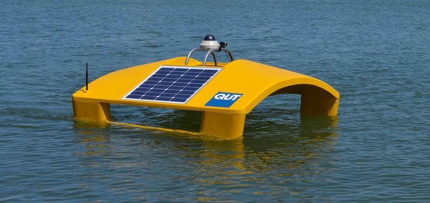
4                                                                   Matthew Dunbabin

   The overall coordination of the mobile sensors (robots) is critical to accurately
measure spatiotemporal environmental processes. An emerging research area for
ASVs is that of mobile adaptive sampling where the ASV can alter its trajectory
to improve measurement resolution in space and time (e.g. [17]). The survey pa-
per [3] summarises advances in robotic adaptive sampling for environmental mon-
itoring. Past research has focused primarily on the Gaussian Process-based recon-
struction of stationary processes using combinations of mobile and static sensors
networks [17, 8]. Whilst demonstrating the ability to capture and reconstruct various
parameter distributions, these studies offer simulation only or short duration small-
scale experimental validation. Larger-scale adaptive coordination of mobile sensing
assets (underwater gliders) has been considered for tracking large oceanographic
plumes in [10, 15]. Developing and demonstrating multi-robot adaptive sampling
algorithms for the large-scale monitoring and tracking of spatiotemporal environ-
mental processes is an over-arching goal of this research.

3 The Inference Autonomous Surface Vehicle

This section describes the current Inference Robotic Adaptive Sampling system and
the greenhouse gas sampling payload system as applied and evaluated in this paper.

3.1 High-Level Scenario

The Inference Robotic Adaptive Sampling system was developed with the goal of
providing a shared resource of multiple networked ASVs to allow researchers to
remotely evaluate new sampling algorithms on real-world processes over extended
periods of time. A typical use scenario proposed for the system is outlined below:
1. The ASVs, each carrying a scientific payload, are deployed on a water body.
2. Based on a desired sampling protocol (e.g. random, adaptive) and process mod-
   elling requirements, new sampling locations are determined. This can be achieved
   either from a remote centralised, or an on-board decentralised process.
3. Determine which ASV goes to each of the updated sample locations. This may
   involve optimising a cost function (e.g. minimising energy and/or travel time,
   maximising solar energy harvesting).
4. Each ASV navigates to their commanded sampling location.
5. Each ASV takes its scientific measurement and reports it back through the net-
   work.
6. Repeat steps 2 - 5 until a termination condition is met.
   The system described in this paper is working towards this goal with a prelimi-
nary experimental evaluation of this scenario using a simplified random exploration
algorithm as described in Section 4.
Autonomous Greenhouse Gas Sampling using Multiple Robotic Boats                                   5

3.2 Hardware Overview

The Autonomous Underwater Vehicles used in the multi-robot Inference system are
custom designed for persistent and cooperative operation in challenging inland wa-
terways. The overall hull shape (see Figure 2) has four key features; (1) A low draft
allowing traversal in shallow water, (2) open sides and low curved top deck to min-
imise windage and the associated drift when station keeping during sampling, (3) a
large top surface area angled for maximising energy harvesting from the solar pan-
els, and (4) a moon-pool (open centre section) with standardised attachment points
to mount custom sensor packages. The overall dimensional and mass specifications
for the ASVs are given in Table 1.

Fig. 2 One of the Autonomous Surface Vehicles from the Inference system. The navigation sen-
sors, computing and batteries are located underneath the two solar panels. The scientific payload is
attached to the moon-pool opening underneath the camera. Note the pan-tilt dome camera visible
was not used in this study, only the smaller USB camera directly in front of it.

    Propulsion of the ASVs is provided by two BlueRobotics T100 brushless thrusters
mounted at the rear of each side of the hull. These provide the forward motion as
well as steering (through differential control) of the vehicles. The system is powered
by a single 20 Ah Lithium Iron Phosphate battery and two 40 W solar panels. This
limited energy capacity requires advanced path-planning algorithms to coordinate
the ASVs for maximising energy harvesting as well as to meet the overall sampling
objectives. These algorithms are current ongoing research and not considered in this
paper.
    The ASVs are required to autonomously navigate inland waterways using only
their on-board sensors. Each ASV has a suite of low-cost navigation sensors which
include a GPS, magnetic compass with roll and pitch, and a depth sensor for mea-
suring bathymetry. Of particular importance is the ability to detect the water’s edge
and potential obstacles on top of the water. The obstacle sensors used in this study
are a USB camera (Microsoft LifeCam) mounted above the moon-pool, and four
Maxbotix ultrasonic range sensors mounted just under the leading and trailing edges
of the top deck. These sensors are used to detect the edge of the water and at-surface
structure such as reeds, trees and water lilies (see Section 4). To minimise power
6 Matthew Dunbabin
Table 1 Physical and performance specifications of the ASVs.
General Specifications
Length 1.50 m
Width 1.55 m
Height (above waterline) 0.7 m
Draft 0.15 m
Weight 33 kg (without payload)
External payload: 4 kg
Propulsion 2 x BlueRobotics T100 brushless electric thrusters
Power 12V 20Ah LFP battery
2 x 40 W solar panels
Speed Max: 2.3 ms−1
Typical survey: 0.5 - 0.8 ms−1
consumption and cost, typical scanning laser-based or radar sensors are not cur-
rently used, although they can be added if required in future scenarios.
The ASV’s thrusters are controlled via a custom designed motor and sensor inter-
face board. This system is capable of providing waypoint control and ultrasonic and
depth sensor based obstacle avoidance. To facilitate vision-based obstacle avoid-
ance, each ASV has an Odroid C1 ARM Cortex-A5 1.5Ghz quad core CPU running
the Robotic Operating System (ROS) and OpenCV.
There are two communication systems on-board the ASVs. The first is a 2.4 GHz
WiFi system allowing communication to a gateway located on a floating platform
on the water storage. This gateway has a wireless router and 3G modem allowing
bidirectional data transfer from a centralised server located at the Queensland Uni-
versity of Technology. The second is a 2.4 GHz wireless embedded system (XBee
IEEE 802.15.4) allowing serial communication between each vehicle as well as with
existing static floating sensor nodes.
Each ASV is capable of carrying additional custom payloads weighing up to 4
kg. The payload is mounted under the moon-pool opening via six attachment bolts.
Currently available payloads include gas sampling (see Section 3.3), multi-beam and
profiling sonars, water sampling and a winch system for water column profiling. A
six pin connector is provided for use by the custom payloads. This connector pro-
vides power as well as bi-directional serial communications via a standardised pro-
tocol for triggering sampling, and reporting sample completion and possible faults.
3.3 Gas Sampling System
The goal of this study is to measure greenhouse gas emissions (efflux) from the wa-
terway. Figure 3 shows the self-contained greenhouse Gas Sampling System (GSS)
developed to autonomously measure both the diffusive and ebullitive efflux. This
payload is mounted underneath the ASV via the moon-pool payload attachment
points as described in Section 3.2.Autonomous Greenhouse Gas Sampling using Multiple Robotic Boats 7 Fig. 3 The Gas Sampling System (GSS) used to measure greenhouse gas (methane) release to atmosphere from the inland water storages. The GSS is attached to the ASV as described in Sec- tion 3.2. The GSS (Figure 3) automates the traditional manual chamber-based sampling process and consists of three primary components; (1) A frame allowing the lower- ing and raising of a chamber into the water, (2) a chamber fitted with a continuous methane gas (CH4 ) sensor and purge valve, and (3) a physical gas sampling unit. The process of sampling the greenhouse gas being released from the water to the atmosphere using the GSS is illustrated in Figure 4 and consists of four steps. Firstly, the ASV navigates to the desired sampling location it goes into a weak station-keeping mode. This limits the control input to the motors to reduce any dis- turbance that may influence the CH4 efflux at the expense of a slightly increased station bound. At this point, the chamber purge valve (see Figure 3) is opened and the chamber lowered using the linear actuator to achieve a desired air volume within the chamber (Figure 4(A-B)). The second step involves closing the chamber purge valve and letting the methane concentration within the chamber increase for a prede- termined incubation time (see Section 4 for a discussion on incubation time). During incubation, the methane sensor continuously measures the concentration within the chamber (Figure 4(B-C)). At the end of the incubation, the third step (Figure 4(C)) calculates the overall gas efflux rate from the gradient of the recorded methane con- centration time history. Also a physical sample of gas from the chamber is collected for laboratory analysis using the gas sampling unit (see Figure 3). This involves a sequence of actions that firstly purges the sample tube using the pump, then loads a pre-evacuated 12 mL vial into the sampling unit. A linear actuator on the unit drives a hypodermic needle into the vial whilst pumping gas from the chamber. Once 20 mL of gas has been pumped into the vial (over pressure sampling technique), the needle retracts and the unit discharges the vial ready for the next sample.
8                                                                          Matthew Dunbabin

Fig. 4 The sequence of actions required to measure greenhouse gas using the GSS.

   After sampling is completed, the final step involves opening the chamber purge
valve and raising the chamber out of the water. At this point the ASV can move to
the next sample location.

4 Technical Approach

This section outlines technical details relating to the sampling of greenhouse gas
(methane), obstacle avoidance, and the sample site selection algorithms used for
coordinating a number of the ASVs across a previously unexplored water body.

Gas Sampling Protocol

During the sampling phase, the concentration measured by the methane sensor is
polled every 2 seconds for the entire incubation period. A linear least squares line
of best fit applied to this time history and the gradient used to calculate the flux rate.
   A key consideration for greenhouse gas sampling is determining the minimum
incubation time that maximises detection accuracy. The output from the continuous
methane sensor in the GSS is quantised to 0.01%. While diffusive fluxes are typ-
ically less than 50 mg m−2 d−1 , ebullitive fluxes in our region can be has high as
22,000 mg m−2 d−1 [6]. Varying the incubation time and/or head-space ratio (i.e.
the ratio of chamber surface area (Ac ) to its internal air volume (Vc )) can be used
to achieve a desired detection accuracy. Figure 5 shows the predicted variability in
relative measurement error (i.e. the percentage error between a true methane flux
to that which can be measured by the GSS) versus incubation time for different
methane efflux rates and head-space ratios. As can be seen, longer incubation times
lead to reduced errors as with increasing head-space ratios. However, longer incu-
bation times mean less sample points can be performed per day. In this study, the
primary interest is the detection of methane “hot-spots”, that is where it is bubbling
from the water. Therefore, incubation times of 15 - 20 minutes were chosen here
Autonomous Greenhouse Gas Sampling using Multiple Robotic Boats                            9

Fig. 5 The predicted per-
centage relative measurement
error of methane flux rate with
incubation time for the pro-
totype GSS (see Section 3.3)
with a sensor output reso-
lution of 0.01%. Two efflux
rates are considered, 1000
and 5000 mg m−2 d−1 with
head-space ratios (Ac /Vc ) of
10 and 20 m−1 ).

to allow detection of methane rates as low as 1000 mg m−2 d−1 , albeit at lower
accuracy. However, the higher the efflux rate, the more accurate the measurement.

Obstacle Avoidance

The ASVs have three sensors for obstacle avoidance; (1) ultrasonic sensors, (2) a
camera, and (3) water depth sensor. The ultrasonic sensors have a maximum range
of 6.5 m and are used to detect above water objects in front of the ASV such as
land, reeds, trees and larger buoys. The camera, only used when moving between
sample waypoints, is used to detect water lilies on the water’s surface. The image
stream is processed at 1 Hz. With the camera fixed to the ASV, the horizon can be
approximated and only the scene below the horizon considered. Image segmentation
is conducted using an empirically determined threshold on the green and blue color
channels with an approximate water lily size threshold to reduce noise. Figure 6
shows an example image from an ASV and the resulting segmentation of the water
lilies (shown in red).

Fig. 6 Example of image segmentation from the ASV for detecting on-water obstacles such as
water lilies (Left: original image. Right: image with detected obstacles highlighted in red).

   To detect shallow, non-traversable water, the depth of water below the ASV is
continuously monitored. The outputs from all obstacle sensors are parsed by the
10                                                                     Matthew Dunbabin

on-board controller. When a detection occurs, the ASV trajectory is modified as
described in the following section.

Multi-Robot Sample Site Selection

A random walk-based algorithm is proposed here for selecting locations for n ASVs
to sample the environment in an attempt to identify regions with high methane gas
flux. There are two key assumptions: (1) the boundary of the water body is known
from sources such as GIS, and (2) the ASVs can communicate between each other
and can share their list of previous and next sample locations. In this study, we do
not use bathymetry but it could be used in the future to help guide the algorithm.
   The selection of new sample locations is based on an online random walk and
potential fields. Iterating through each robot, the basis of the algorithm is as follows:
1. All previously sampled sites for all robots are represented as 2D Gaussian poten-
   tials centred at those points with fixed amplitude and standard deviation.
2. A random position at radius r from the current position is selected. If this position
   is not on land, and the value from the closest Gaussian potential is less than a
   threshold, this becomes the next sample point for that robot. If this condition is
   not met, the process is iterated until a location can be found. If no location can
   be found after a set number of iterations, the search radius is increased by ∆ r and
   the process repeated until a site is found or some termination criteria is met.
3. To increase local intensification of sampling in methane “hot-spots”, if the mea-
   sured flux rate at the robot’s current location exceeded some threshold, the search
   radius for the next sample step is set to β r where (0 < β ≤ 1) and the potential
   threshold trigger relaxed.

    During waypoint execution each robot drives in a straight line towards the goal.
If the water depth falls below a threshold (i.e., too shallow), or an obstacle is de-
tected, the vehicle starts to move either clockwise or counter clockwise around the
contour until a new straight line to the goal can be achieved. This entire process is
repeated for all robots until a desired number of samples are collected or some other
termination condition met.

5 Results

An experimental evaluation using two ASVs with gas sampling payloads was con-
ducted on two water reservoirs in South East Queensland, Australia; (1) Gold Creek
Dam, and (2) Little Nerang Dam. These are established study sites and selected as
they exhibit regions of significant methane ebullition and provide a range of chal-
lenging operational conditions for evaluating robotic systems.
   Previous studies [6] had collected georeferenced outlines of the water’s edge
(boundary) as well as bathymetry maps for both sites. Only the boundary was used
Autonomous Greenhouse Gas Sampling using Multiple Robotic Boats 11
Fig. 7 The two ASVs at the start of a sampling campaign on Gold Creek Dam, Queensland. The
retracted gas sampling unit is visible underneath the ASV on the right.
in this study for implementing the sample site selection algorithm described in Sec-
tion 4. Figure 7 shows the two ASVs used in this study on Gold Creek Dam.
The first experiment was conducted at Gold Creek Dam. This is a small, relatively
open dam with a narrowing distal arm. The sample selection algorithm was run to
collect 12 samples for each ASV, with a step radius of 100 m, and intensification
factor of 0.5. The trigger was set at 1000 mg m−2 d−1 with 20 minute incubations.
The time to complete the sampling was approximately 5 hours. Figure 8 shows the
results of implementing the sample strategy for both ASVs. These results show the
ASVs were capable of navigating the water storage and implementing the sample
protocol. The online detections of methane exceeding the trigger threshold (markers
in yellow) correspond to areas physically observed to have methane ebullition. As
ebullition is essentially a point source emitter, there can be extreme variability even
at short spatial and temporal scales (see [6]). Therefore, whilst ebullition can often
be seen in expected regions (e.g. top image of Figure 8) a sample within that region
does not always guarantee the capture of gas bubbles sufficient to achieve high rates.
A second experiment was conducted at Little Nerang Dam. This is a longer and
narrower water storage with a steep sided catchment. The sample selection was run
with a total of 30 samples for each ASV, step radius of 200 m and an intensification
factor of 0.5. The trigger was set at 1000 mg m−2 d−1 with 15 minute incubations.
The time to complete the experiment was approximately 10.5 hours.
Figure 9 shows the results of implementing the sample strategy for both ASVs.
These results again show the ASVs ability to implement the sample protocol and
navigate the water storage. The online detections of methane exceeding the trigger
threshold (markers in yellow) are consistent with previous research at the dam [6].
Whilst these experiments demonstrated the system for real-time sampling of
greenhouse gases across water bodies, the online component of gas sampling sys-
tem was not optimised for detecting lower (and more common) flux rates of less than12 Matthew Dunbabin Fig. 8 Sampling locations and ebullition detections from 20 minute incubations using two ASVs on Gold Creek Dam, Queensland. Top: An aerial image of Gold Creek Dam with red overlay showing the regions of physically observed methane ebullition. Lower: The trajectory and resulting sample locations indicated by the circles for ASV1 and triangles for ASV2. The start location for both ASVs is indicated by the green dot. The circles and triangles highlighted in yellow indicate the online chamber measurements that exceeded 1000 mg m−2 d−1 . 1000 mg m−2 d−1 . Future work will look at adaptive chamber head-space control as well as higher precision sensors to improve the utility of the system for accurate quantification of the combined diffusive and ebullitive flux of greenhouse gases. 6 Conclusions This paper has presented a novel robotic sampling system for conducting large- scale, persistent monitoring on complex inland waterways. The system, named In-
Autonomous Greenhouse Gas Sampling using Multiple Robotic Boats                                 13

Fig. 9 Sampling locations and ebullition detections from 15 minute incubations using two ASVs
on Little Nerang Dam, Queensland. Left: An aerial image of Little Nerang Dam with red overlay
showing the regions of physically observed methane ebullition. Right: The trajectory and resulting
sample locations indicated by the circles for ASV1 and triangles for ASV2. The start location
for both ASVs was at the dam wall located at the northern most end. The circles and triangles
highlighted in yellow indicate the online chamber measurements that exceeded 1000 mg m−2 d−1 .

ference, consists of multiple networked Autonomous Surface Vehicles (ASVs) car-
rying a range of scientific payloads. Experimental results demonstrate the ASV’s
ability to navigate complex waterways whilst executing a multi-robot online sam-
pling protocol. Using a custom Gas Sampling System (GSS) attached to each ASV,
experimental results also show the robotic system is capable of measuring and lo-
calising strong greenhouse gas release (methane) to atmosphere. Future research is
focused on developing more sophisticated multi-robot adaptive sampling algorithms
to achieve persistent monitoring and mapping of spatiotemporal processes whilst
considering energy, speed and sampling constraints of the vehicles. Additionally,
new sensors and algorithms for head-space control of the GSS are being developed
to improve its lower detection limit for sampling regions with low gas flux rates.

Acknowledgements The author would like to thank Alistair Grinham and Katrin Strum from the
University of Queensland for their assistance with the initial gas sampling unit and ASV prototype
evaluation, and laboratory processing of gas samples. Also thanks to Riki Lamont for his assistance
in the payload integration and commissioning of the ASVs.
14                                                                             Matthew Dunbabin

References

 1. M. Dunbabin and A. Grinham. Experimental evaluation of an autonomous surface vehicle for
    water quality and greenhouse gas monitoring. In Proc. International Conference on Robotics
    and Automation, pages 5268–5274, May 2010.
 2. M. Dunbabin, A. Grinham, and J. Udy. An autonomous surface vehicle for water quality
    monitoring. In Proc. Australasian Conference on Robotics and Automation, December 2009.
 3. M. Dunbabin and L. Marques. Robots for environmental monitoring: Significant advance-
    ments and applications. Robotics Automation Magazine, IEEE, 19(1):24–39, March 2012.
 4. C. Ferreira, A. Almeida, J. Martins, N. Almeida, E. Dias, and E. Silva. Autonomous
    bathymetry for risk assessment with ROAZ robotic surface vehicle. In Proc. Maritime Systems
    and Technology Americas 2010, 2010.
 5. M-E. Garneau, T. Posch, G. Hitz, F. Pomerleau, C. Pradalier, R. Siegwart, and J. Pernthaler.
    Short-term displacement of planktothrix rubescens (cyanobacteria) in a pre-alpine lake ob-
    served using an autonomous sampling platform. Limnology and Oceanography, 58(5):1892–
    1906, 2013.
 6. A. Grinham, M. Dunbabin, D. Gale, and J. Udy. Quantification of ebullitive and diffusive
    methane release to atmosphere from a water storage. Atmospheric Environment, 45(39):7166
    – 7173, 2011.
 7. G. Hitz, F. Pomerleau, M.-E. Garneau, C. Pradalier, T. Posch, J. Pernthaler, and R.Y. Siegwart.
    Autonomous inland water monitoring: Design and application of a surface vessel. Robotics
    Automation Magazine, IEEE, 19(1):62–72, March 2012.
 8. V. Hombal, A. Sanderson, and D.R. Blidberg. Multiscale adaptive sampling in environmental
    robotics. In Multisensor Fusion and Integration for Intelligent Systems (MFI), 2010 IEEE
    Conference on, pages 80–87, Sept 2010.
 9. J. Leedekerken, M. Fallon, and J. Leonard. Mapping complex marine environments with au-
    tonomous surface craft. In Experimental Robotics, volume 79 of Springer Tracts in Advanced
    Robotics, pages 525–539. Springer Berlin Heidelberg, 2014.
10. N. E. Leonard, D. A. Paley, R. E. Davis, D. M. Fratantoni, F. Lekien, and F. Zhang. Coordi-
    nated control of an underwater glider fleet in an adaptive ocean sampling field experiment in
    monterey bay. Journal of Field Robotics, 27(6):718–740, 2010.
11. V. St Louis, C. Kelly, E. Duchemin, J. Rudd, and D. Rosenberg. Reservoir surfaces as sources
    of greenhouse gases to the atmosphere: A global estimate. Bioscience, 50:766–775, 2000.
12. J. Manley and S. Willcox. The wave glider: A persistent platform for ocean science. In
    OCEANS 2010 IEEE - Sydney, pages 1–5, May 2010.
13. P.F. Rynne and K.D. von Ellenrider. A wind and solar-powered autonomous surface vehicle
    for sea surface measurements. In Proc. IEEE OCEANS 2008, pages 1–6, September 2008.
14. S. Scherer, J. Rehder, S. Achar, H. Cover, A. Chambers, S. Nuske, and S. Singh. River map-
    ping from a flying robot: state estimation, river detection, and obstacle mapping. Autonomous
    Robots, 33(1-2):189–214, 2012.
15. R. Smith, J. Das, Yi Chao, D. Caron, B. Jones, and G. Sukhatme. Cooperative multi-AUV
    tracking of phytoplankton blooms based on ocean model predictions. In OCEANS 2010 IEEE
    - Sydney, pages 1–10, 2010.
16. J. Wang, W. Gu, and J. Zhu. Design of an autonomous surface vehicle used for marine en-
    vironmental monitoring. In Proc. International Conference on Advanced Computer Control
    (ICACC09), pages 405–409, January 2008.
17. B. Zhang and G.S. Sukhatme. Adaptive sampling for estimating a scalar field using robotic
    boat and a sensor network. In Proc. International Conference on Robotics and Automation,
    pages 3673–3680, April 2007.
You can also read