Best practices for high penetration PV in insular power systems 2021
←
→
Page content transcription
If your browser does not render page correctly, please read the page content below

3

Task 14 Solar PV in the 100% RES Power System
PVPS

                      Best practices for high
                      penetration PV in insular
                      power systems
                     2021

                                                Report IEA-PVPS T14-13:2021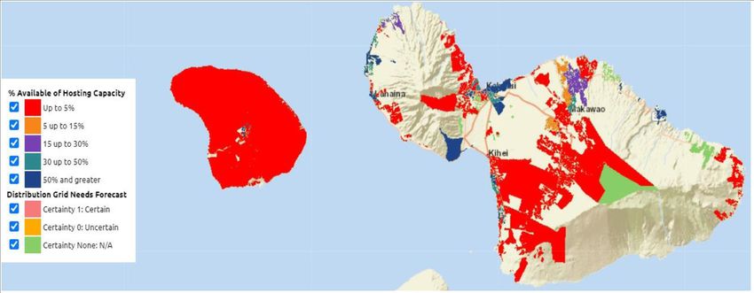
Task 14 – Best practices for high penetration PV in insular power systems

What is IEA PVPS TCP?
The International Energy Agency (IEA), founded in 1974, is an autonomous body within the framework of the Organization
for Economic Cooperation and Development (OECD). The Technology Collaboration Programme (TCP) was created with
a belief that the future of energy security and sustainability starts with global collaboration. The programme is made up of
6.000? experts across government, academia, and industry dedicated to advancing common research and the application
of specific energy technologies.

The IEA Photovoltaic Power Systems Programme (IEA PVPS) is one of the TCP’s within the IEA and was established in
1993. The mission of the programme is to “enhance the international collaborative efforts which facil itate the role of
photovoltaic solar energy as a cornerstone in the transition to sustainable energy systems.” In order to achieve this, the
Programme’s participants have undertaken a variety of joint research projects in PV power systems applications. The
overall programme is headed by an Executive Committee, comprised of one delegate from each country or organisation
member, which designates distinct ‘Tasks,’ that may be research projects or activity areas.

The IEA PVPS participating countries are Australia, Austria, Belgium, Canada, Chile, China, Denmark, Finland, France,
Germany, Israel, Italy, Japan, Korea, Malaysia, Mexico, Morocco, the Netherlands, Norway, Portugal, South Africa, Spain,
Sweden, Switzerland, Thailand, Turkey, and the United States of America. The European Commission, Solar Power
Europe, the Smart Electric Power Alliance (SEPA), the Solar Energy Industries Association and the Cop - per Alliance are
also members.

Visit us at: www.iea-pvps.org

What is IEA PVPS Task 14?
The objective of Task 14 of the IEA Photovoltaic Power Systems Programme is to promote the use of grid-connected PV
as an important source in electric power systems at the higher penetration levels that may require additional efforts to
integrate dispersed generators. The aim of these efforts is to reduce the technical barriers t o achieving high penetration
levels of distributed renewable systems.

       Authors
             ➢      Main Content:
                    Task 14: Ricardo Guerrero-Lemus (Spain), Kenn H.B. Frederiksen (Denmark), Lionel Perret
                    (Switzerland), Iain MacGill (Australia), Yuzuru Ueda (Japan), Gunter Arnold (Germany).
                    Guest contributions: Les. E. Shephard (USA), Julieta Giraldez (NREL, USA), Andy Hoke (NREL,
                    USA), Brad W. Rockwell (KIUC, USA), Dale Philip (UNSW, Australia).

       ➢    Editors: R. Guerrero-Lemus (Main Editor), Les E. Shephard, Julieta Giraldez, Andy Hoke.

    DISCLAIMER
    The IEA PVPS TCP is organised under the auspices of the International Energy Agency (IEA) but is functionally and legally autonomous.
    Views, findings and publications of the IEA PVPS TCP do not necessarily represent the views or policies of the IEA Secretariat or its
    individual member countries
    COVER PICTURE
    Landscape in Tenerife (Canary Islands), Emilio Gutiérrez Delgado
    ISBN 978-3-907281-20-8
INTERNATIONAL ENERGY AGENCY
      PHOTOVOLTAIC POWER SYSTEMS PROGRAMME

Best practices for high penetration PV in
         insular power systems

                  IEA PVPS
                   Task 14

        Report IEA-PVPS T14-13:2021

           ISBN 978-3-907281-20-8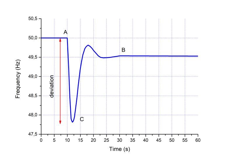
Task 14 – Best practices for high penetration PV in insular power systems

  TABLE OF CONTENTS

  Acknowledgements............................................................................................................................. ............           3
  List of Abbreviations.......................................................................................................................................         4
  Executive Summary........................................................................................................................................            5
  1.           Introduction............................................................................................................................. ..........    8
               1.1.          Motivation...........................................................................................................................     8
               1.2.          Definition of Insular Power System....................................................................................                    9
               1.3.          Key parameters for insular power systems........................................................................                          10
  2.           Fundamentals of insular power systems..........................................................................................                         13
               2.1.          Grids in insular power systems..........................................................................................                  13
               2.2.          Grid codes in insular power systems.................................................................................                      15
               2.3.          Frequency response..........................................................................................................              16
               2.4.          Interconnections.................................................................................................................         18
               2.5.          Storage........................................................................................................... ....................   20
               2.6.          Power electronics...............................................................................................................          23
  3.           Resilience considerations for insular power systems.......................................................................                              25
               3.1.          Introduction........................................................................................................................      25
               3.2.          Lessons learned on insular power systems resilience.......................................................                                26
               3.3.          Resilience of renewable generation assets.......................................................................                          27
  4.           Overview of best practices in insular power systems......................................................................                               31
               4.1.          Coober Pedy (Australia)....................................................................................................               31
               4.2.          Easter Island (Chile)..........................................................................................................           33
               4.3.          El Hierro (Spain)................................................................................................................         36
               4.4.          Galápagos (Ecuador).........................................................................................................              40
               4.5.          Kauai (US)..........................................................................................................................      42
               4.6.          King Island (Australia)........................................................................................................           44
               4.7.          Maniitsoq City (Greenland - Denmark)...............................................................................                       47
               4.8.          Maui (US)...........................................................................................................................      48
               4.9.          Nii Jima and Shikin Jima (Japan).......................................................................................                   53
               4.10.         Tenerife (Spain).................................................................................................................         54
  5.           Summary and Outlook......................................................................................................................               58
               5.1.          Technical planning and operation changes to accommodate high DPV capacity.............                                                    58
               5.2.          Present and future advance controls for renewable and inverter-coupled generation......                                                   59
  6.           Selected key findings and recommendations...................................................................................                            62
               6.1.          Fundamentals of insular power grids.................................................................................                      62
               6.2.          Resilience considerations..................................................................................................               63
               6.3.          Summary of best practice case studies in insular power systems.....................................                                       63
               6.4.          Outlook...............................................................................................................................    65
  References......................................................................................................................................................     66

                                                                                                                                                                            2
Task 14 – Best practices for high penetration PV in insular power systems

ACKNOWLEDGEMENTS

This IEA-PVPS report received valuable contributions from several IEA-PVPS Task 14
members and other international experts. Many thanks to all of them. Special thanks
are expressed to all guest contributors outside Task 14 members.

                                                                                      3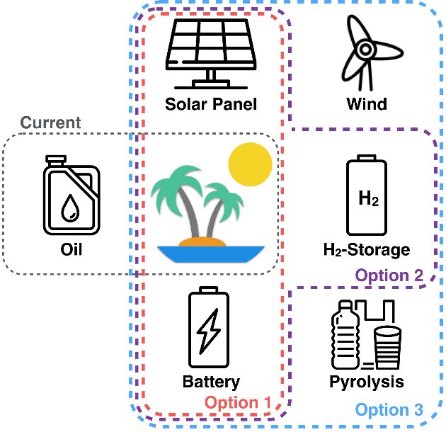
Task 14 – Best practices for high penetration PV in insular power systems

LIST OF ABBREVIATIONS

  DER                   Distributed Energy Resources
  DMS                   Distribution Management System
  DPV                   Distributed Photovoltaics
  DSO                   Distribution System Operator
  HV                    High Voltage
  HVDC                  High Voltage Direct Current
  IEA                   International Energy Agency
  IEC                   International Electrotechnical Commission
  LV                    Low Voltage
  MV                    Middle Voltage
  PV                    Photovoltaics
  RES                   Renewable Energy Sources
  TSO                   Transmission System Operator
  UFLS                  Under Frequency Load Shedding

                                                                            4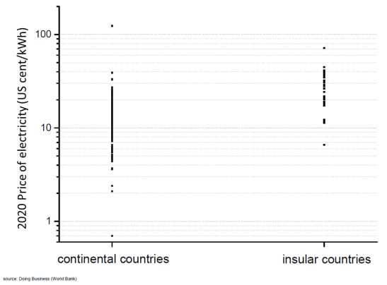
Task 14 – Best practices for high penetration PV in insular power systems

EXECUTIVE SUMMARY

Insular territories are uniquely positioned as global laboratories for transforming our
energy future as many of them are the first to encounter the emerging perturbations in
the earths’ systems response to climate change. While each insular territory is unique
in its own right, they share several attributes (e.g., isolation, lack of interconnections,
limited land availability, seasonal population variations, etc.) and a common goal to
reduce electricity costs, limit carbon emissions and ensure a stable electricity grid for
sustained economic development. This unique combination of increasing vulnerability
and decreasing reliability is driving many insular territories to accelerate the
deployment of renewable energy systems for their future while experimenting with
innovative solutions and best practices that are applicable to many other areas across
the globe. This report summarizes the general attributes of insular power systems that
support these territories emphasizing best practices and key insights that have
accelerated their transformation, have impeded their progress and/or are relevant to
more traditional power systems globally.

As the share of traditional photovoltaic and wind energy generation sources increase
in insular power systems, system stability (e.g. expressed by parameters such as
frequency deviations, voltage transients) also tends to decrease. Insular systems
experience more frequent instabilities in part because of the basic attributes that drive
electricity demand (e.g., seasonal tourism), capacity (grid size, increasing renewable
penetration, disruptions of generation, etc.) and a lack of interconnections to other
power systems. To mitigate these detrimental impacts, system operators regularly
focus on several actions including ongoing power system modifications,
counterbalancing renewable energy fluctuations with flexible generation, curtailment of
renewable systems, or load shedding. Insular power systems are also among the first
to deploy advanced technologies that leverage the capabilities of fast-responding
power electronics to enhance grid stability.

Solar PV is being deployed at an accelerating rate in insular power systems for a
number of reasons including reduced cost, improved versatility in deployment scale,
and ease of maintenance and operations. The cost of solar PV system components
continues to decrease and overall system costs are only moderately impacted by
system scale. Many insular territories are located in areas with high solar irradiance,
high population densities and significant rooftop space which helps preserve limited
available land for other purposes. Distributed photovoltaics in particular are growing at
an accelerated rate, and distributed PV systems increasingly include energy storage
due to the increasing availability and the decreasing cost of battery storage. This
distributed storage capability can be used to support the grid, or simply to maximize
the benefits for the owner (i.e., to maximize the distributed use of generated power).

Storage is the principal option for integrating large shares of non-dispatchable energy
in insular power systems. Storage systems today primarily include batteries and
pumped hydropower. Storage is critical to balance large amounts of wind and solar PV
power under secondary and/or tertiary regulation and to manage seasonal variations

                                                                                              5
Task 14 – Best practices for high penetration PV in insular power systems

in demand and generation capacity throughout the year. As renewable generation
sources increase on the grid, the inherent characteristics of synchronous generators
that typically contribute significantly to grid stability diminish. In insular power systems
relying on RES based generation fast response capabilities from static power-
electronic based generation are increasing. Indeed, these new capabilities are starting
replacing the legacy of synchronous generators and the reliance on inertia and
mechanical frequency response approaches to maintain system reliability.

Insular power systems serve as an excellent test bed and learning center for assessing
best practices that have significant relevance to improving the resilience of power
systems in all locations around the globe. The challenges associated with assuring a
resilient insular power system, defined by our ability to anticipate and adapt to changing
conditions that influence the power system or to respond to, withstand or recover
rapidly from disruptions, are substantial and require a disciplined and systematic
planning and implementation process to mitigate those factors most likely to impact
system resilience.

Based mostly on the evolution of the PV technology, case studies reported and lessons
learned in this Report, the most important recommendations for insular power systems
are the following:

      •      Insular power systems serve as a global learning collaboratory for transforming
             the global energy system and accelerating the deployment of traditional and
             non-traditional renewable energy capabilities that integrate technology, policy,
             economics and regulation.
      •      When deploying renewable technologies, performance specifications should
             take into account the likely future state of the insular power system, which may
             include greatly reduced conventional generation. It is typically costly and
             logistically difficult to retrofit advanced features after installation.
      •      All new renewable generation should be required to be capable of continuing to
             operate during (riding through) large voltage and frequency transient events,
             including fast rates of change of frequency. A retrofit of existing renewable
             generation shall also be considered, maybe based on a cost-benefit analysis.
      •      Small-scale distributed generation that is not under direct utility control can be
             more beneficial if equipped with the ability to autonomously respond to voltage
             and frequency events in a way that helps stabilize the system.
      •      It is important to apply specific settings (e.g., inverter functions and protections)
             in insular systems, and not to use only “default” settings designed for the large
             mainland power grids. Frequency and voltage variations might be larger and
             faster in insular systems, which could lead to an unwanted tripping and loss of
             RES generation.
      •      Large-scale renewable generation should be capable of providing grid
             stabilizing services such as voltage regulation and fast frequency response in
             coordination with the local TSO. In systems where non-synchronous generation
                                                                                                     6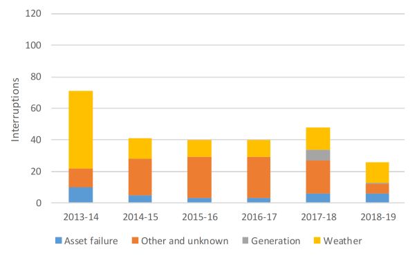
Task 14 – Best practices for high penetration PV in insular power systems

             may in the future exceed 80% of instantaneous load at times, grid-forming
             capability should be considered for system relevant new generation.
      •      Maintaining an emphasis on grid resilience during all phases of planning,
             design, deployment and operation of large-scale renewable systems is critical
             to assure cost effective, reliable and efficient customer service and system
             response.

                                                                                             7
Task 14 – Best practices for high penetration PV in insular power systems

1. INTRODUCTION

1.1. Motivation
Insular territories1 are highly motivated to play a significant and critical role in
transforming our global energy future because they are most vulnerable if this
transformation does not occur. Insular territories are uniquely positioned on the critical
path to address the challenges associated with climate change and must adapt and
lead the way to survive. Insular territories often have isolated electrical grid systems,
with limited or no interconnections, and today are generally migrating from a past
reliance on expensive, imported fossil fuel for electricity generation to a future that
embraces low carbon generation sources. While interconnections are important for
many insular systems to maintain reasonable standards for grid reliability, many are
completely isolated; hence they must be early adopters and innovators because they
have no choice. This unique combination of vulnerability to ongoing changes induced
by climate change, high cost of electricity, limited interconnections and low reliability of
the isolated electric grid is driving many insular territories to accelerate the deployment
of renewable energy systems (RES) for their future while experimenting with innovative
solutions and best practices that are applicable in many other areas across the globe,
including, and well-beyond, insular territories.

The cost of electricity generated in insular power systems is often significantly higher
than in large interconnected systems because of economies of scale, transportation
costs, and energy markets that are largely controlled by a monopoly with few or no
options for consumers. The lack of interconnections also limits the development of
100% RES insular power systems unless they are supported by alternative renewable
resources including hydro, geothermal or biomass systems that are capable of
providing quasi-base load supplies, and/or, as a second emerging alternative, by
storage and power electronics capable of providing full renewable electricity and fast
frequency response (FFR). However, planning based on the first alternative is often
contested locally because of concerns over emissions and increased potential for
earthquakes with geothermal, flooding of land with hydro, and air quality from
combustion of biomass near populated areas. Wind is another expected contributor to
large RES deployments and can be used to support pumped hydro-storage. However,
wind turbines is constrained in many islands because of the environmental impact
mostly on fauna, doubts about resilience against hurricanes and logistical difficulties in
small islands.

Solar PV is being used at an accelerating rate in RES insular power system
deployments for a number of reasons that include cost, versatility in deployment scale,
and ease of maintenance and operations, among others. The cost of solar PV system
components continues to decrease, overall system costs are only moderately impacted

1
  Insular territories include both independent nation states (e.g. Tonga and Aruba) islands and other territories (e.g., Canary Islands) that
are tied administratively to another nation.

                                                                                                                                                8
Task 14 – Best practices for high penetration PV in insular power systems
by system scale, and they can be monitored remotely from any location in the world.
Many insular territories are located in areas with high solar irradiance, high population
densities and significant rooftop space which helps preserve limited available land for
other purposes. Distributed photovoltaics in particular are growing at an accelerated
rate on insular territories propelled by high electricity costs, favourable policies and the
availability and decreasing cost of battery storage. Grid codes should be adopted or
modified as PV penetration increases to minimize, detect, ride through, and/or
favourably respond to frequency and voltage instabilities often encountered in highly
non-dispatchable RES scenarios. While several challenges remain relative to fully
controlled integration of DPV into the grid that assures effective frequency response
services [1], solar PV will be instrumental in enabling the transformation to 100% RES
deployments in many insular locations around the world.
Interconnections play a prominent role in transforming the power systems of insular
territories where they are available or feasible. Interconnections can readily allow to
increase the share of renewable energy in an insular power system and reduce
electricity costs, mostly when the interconnection is economically viable, and the island
is part of an archipelago or it is close to a large power system. However,
interconnections are expensive, specifically when the seabed is deep and the capacity
required is large, and can also fail unexpectedly (e.g. Mallorca-Menorca
interconnection), emphasizing the need for, at a minimum, a backup power capacity
placed in the insular power system or ready for shipments under emergency
circumstances. Investment trade-offs will likely occur between the availability of
storage systems, or other alternatives, and access to interconnections as the cost of
battery storage, in particular, continues to decrease.
This report is intended to provide the general characteristics, specific conditions and
best practices of insular power systems from selected locations around the globe with
a desire to highlight specific innovative technology, policy, and regulatory practices for
a 100% RES system, based largely on PV.
1.2. Definition of Insular Power System
An insular power system was initially defined as an electric power grid structure in a
physically isolated, geographical area, that is typically an island [2-3]. This definition
has been refined and expanded to recognize the country’s inability due to geographic
size and/or remoteness, to connect with other electricity generators and consumers
outside its borders [4] with access to large, and usually more efficient power markets
because of economies of scale. The expanded definition of insular power systems is
similar to the definition of emerging power systems, where geographic size and/or
remoteness are also main attributes. However, general attributes of insular territories
that must be considered when developing a power system also include a limited range
of available natural resources, a limited ability to achieve economies of scale, seasonal
variations in population, high infrastructure costs, climatic conditions and
microclimates, offshore territories for interconnections, limited waste management,
fisheries, and agriculture dependency. Combining these thoughts, an alternative
definition of insular power systems is a territory that is geographically defined
9Task 14 – Best practices for high penetration PV in insular power systems
by conditions that makes interconnections with large power systems
unattractive economically compared to alternatives based on the combination
of endogenous energy, storage systems, and power electronics.
It is also necessary to add other conventional restrictions to limit the scope of study for
insular power systems. These systems can be classified into four groups: (i) very
small (< 1 MW and < 2 GWh/yr.); (ii) small (1 – 5 MW and 2 – 15 GWh/yr.); medium
(5 – 35 MW and 15 – 100 GWh/yr.); and large (> 35 MW and > 100 GWh/yr.) [2].
The limitation is in terms of peak power demand and annual power demand instead of
other indicators (e.g., population or area) because many islands experience large
seasonal variability in electricity consumption, mostly due to tourism. In general, we
limit our study to medium and large insular power systems because these are the
most complex, challenging and costly for a 100% renewable energy solution to be
implemented. Our study is also limited to insular power systems in IEA countries in
general, except to highlight very specific best practices that may accelerate the
transition to 100% RES production on other islands.
1.3. Key parameters for Insular Power Systems
The first parameter defining the peculiarities of an insular power system is the high
cost of the electricity supplied to customers. The average price of electricity for different
countries can be extracted from the World Bank database (Table I).
Table I: 2020 average price of electricity included in the World Bank Doing
Business Report for selected IEA countries (blue) [5], and for insular territories
(grey).
country USD/kWh1 country USD/kWh1 country USD/kWh1
Antigua and
Barbuda 0,449 Grenada 0,309 Philippines 0,181
Australia 0,204 Haiti 0,211 Portugal 0,222
Bahamas, The 0,285 Iceland 0,122 Samoa 0,385
São Tomé and
Barbados 0,266 Italy 0,168 Principe 0,183
Cabo Verde 0,263 Jamaica 0,264 Seychelles 0,321
Solomon
China 0,146 Japan 0,212 Islands 0,716
Cyprus 0,191 Kiribati 0,413 Spain 0,260
10Task 14 – Best practices for high penetration PV in insular power systems
country USD/kWh1 country USD/kWh1 country USD/kWh1
Comoros 0,281 Korea, Rep. 0,114 Sri Lanka 0,173
St. Kitts and
Denmark 0,242 Madagascar 0,113 Nevis 0,306
Dominica 0,368 Maldives 0,394 St. Lucia 0,321
St. Vincent
Dominican and the
Republic 0,201 Malta 0,190 Grenadines 0,346
Marshall
Fiji 0,218 Islands 0,406 Tonga 0,362
Trinidad and
France 0,136 Mauritius 0,205 Tobago 0,660
Micronesia,
Germany 0,256 Fed. Sts. 0,414 United States 0,181
Greece 0,204 Palau 0,321 Vanuatu 0,382
1
For states the price of electricity is measured in U.S. cents per kWh. A monthly electricity consumption is assumed, for which a bill is then computed for a warehouse based in the largest business city of the economy for the
month of March. The bill is then expressed back as a unit of kWh. The index is computed based on the methodology in the DB16-20 studies.
It should be noted that the price of electricity reported by the World Bank in Table I
includes subsidies and also the values for countries where the cost of electricity is
dramatically affected by extreme economic chaos (e.g., Venezuela showing the
highest price of electricity worldwide). Further, these values do not consider the price
or cost of electricity in insular territories belonging to these countries. However, it is
obvious that the price of electricity in insular countries is higher than in continental ones
(Fig. 1).
Figure 1: 2020 price of electricity for continental and insular countries
considered in the Doing Business Report of the World Bank [5].
11Task 14 – Best practices for high penetration PV in insular power systems
In the case of insular systems belonging to continental countries, (e.g., Hawaii)
sometimes there are substantial differences between the price of electricity in
continental and insular territories. In other cases, countries (i.e., Spain and France)
have approved regulations to assure consistent electricity prices for all the territories
under their jurisdiction. Indeed, in France, the electricity market has been open to
competition since 2007. However, the price of electricity in the islands of Corsica,
Réunion and Guadeloupe is set to mitigate the high generation production costs in
these islands [6]. The inhabitants of these islands are charged a tariff similar to rates
in continental France, and Electricité of France (EDF) is in charge of producing,
distributing and commercializing the electricity. Thus, these islands are subject to a
specific energy policy which requires achieving energy autonomy by 2030. Specific
information about the cost of electricity for the insular power systems studied in this
report is summarized in Table II. In this case, it is important also to refer the data to a
specific year because this cost is greatly affected by the highly variable price of fossil
fuels.
Table II: Generation cost of electricity in 2019 for selected locations and power
mixes discussed in this report. Source: Endesa, KIUC, HECO
Insular System USD/kWh-
EUR/kWh
El Hierro 0,2862 EUR/kWh
Kauai 0,3430 USD/kWh
Maniisoq 0,3500 EUR/kWh
Tenerife 0,1742 EUR/kWh
The collection of data for Table II has been difficult because insular systems use to
have the information not so publicly available that in continental power grids. This is
usually due to the lack of wholesale markets defining the price of electricity under a fair
composition between buyers and sellers. However, some insights can be obtained
from these data, as the strong sensitivity between the size and isolation of the insular
power system and the cost of the electricity, and also the difficulties to obtain a
comparable data, as many time variations are dependent on the taxes system applied
to the insular territory.
12Task 14 – Best practices for high penetration PV in insular power systems
2. FUNDAMENTALS OF INSULAR POWER SYSTEMS
2.1. Grids in insular power systems
To guarantee supply security and reliability in any power system, the frequency of the
grid must lie within a predefined range. If this predefined range is not maintained,
automatic and manual grid protection controls begin to activate to protect equipment
from long term frequency deviations and to assure the power system remains
operational. These out of range frequency excursions are a significant challenge
relative to assuring grid stability in insular power systems trying to reach 100%
renewable energy from variable wind and solar PV resources. Other important
concerns include fault protection, voltage control, and voltage stability (i.e., grid
strength). The unique attributes of insular power systems (e.g., small grids, limited
generation capacity, large seasonal demands, etc.) dictate that innovative and more
resilient strategies must be implemented to assure grid stability.
Currently, kinetic energy from synchronously connected rotating generators (e.g., gas
or steam turbines) and motor loads contribute to maintain operational frequency in the
designated range, providing inertia. The inertia from energy stored in rotating parts of
a turbine-generator can supply a load equal to the rated apparent electric power of the
turbine-generator over a very short, yet defined time period. The inertia is linearly
dependent on the inertial momentum and the square of the mechanical angular velocity
of the rotor and is additive in a power system depending on the number of rotating
units connected to the grid. This contribution is usually expressed in MW·s for large
grid systems.
PV and wind power plants interface to the power grid through power electronic
converters without electromechanical linkage to the system frequency; hence, without
additional control features, they add no inertia to the power system. The same concern
emerges from rotating motor loads connected to the grid through power electronics.
For insular power systems where solar PV, wind and other sources are expanding,
inertia is reduced. This can be mitigated through emerging power electronic synthetic
or virtual inertia which can be introduced in the power system grid codes or as market
services.
Conventional synchronous machines (i.e., rotating electromagnetic devices) contribute
to what is commonly referred to as “strength” of a grid, meaning the ability of the grid
to withstand current disturbances. Thus, strong grids are conventionally classified as
those with many synchronous machines [7], where each synchronous machine acts
as an “anchor” to fix the energy voltage and frequency at selected values and oppose
sudden changes in these parameters in the proximity of the synchronous machine.
The synchronous machines (e.g., turbo-generator drivetrains, hydroelectric plants,
synchronous condensers, or synchronous motor loads) have a magnetic flux in the
core that is resistant to sudden changes, helping to maintain a stable terminal voltage.
Conversely, weak grids are conventionally classified as those that contain relatively
few synchronous machines online. Typically, weak grid regions are those locations
13Task 14 – Best practices for high penetration PV in insular power systems
where large-scale renewable generation is sited far from load or other conventional
generators. Insular power systems can experience sudden weak grid conditions across
the entire grid if large amounts of wind and solar generation are added quickly to the
grid and rapidly displace conventional generation. As solar PV increases significantly
relative to synchronous sources during the day and on weekends when demand is
lower, grid strength decreases. This reduction in grid strength can impact: (i) the
severity of voltage excursions and distortion; (ii) protective relaying accuracy, (iii)
system frequency event severity; and (iv) overall system stability.
As power electronic generation sources (e.g., wind, solar PV, and battery energy
storage) increase on the grid, the inherent characteristics of synchronous generators
that contribute significantly to grid stability diminish, even though the actual power
(MW) produced remains very similar. Further, most power electronic devices depend
on the AC power grid to define wave shapes and internal control functions. A routine
grid event (e.g., switching shunt capacitors and energizing transformers) will produce
greater voltage excursions and distortion on a weaker grid. Protective relays
continuously monitor transmission and distribution lines for faults and disconnect these
lines quickly when a fault is detected. They are designed to operate over a specified
range of grid strength. If the grid strength falls outside of a predefined range, the
protection scheme and relay settings need to be re-evaluated.
The short-circuit ratio (SCR) is one approach that can be used to quantify grid
strength. The SCR can be defined at a particular bus in the grid as the ratio of the
short-circuit current at that bus (in MVA) from only the synchronous machines in the
grid to the MW rating of the power electronic equipment connected locally at the bus
[7]. Values are obtained using complex models and electromagnetic transient
programs. For locations with multiple power electronic plants connected close
together, the Electric Reliability Council of Texas (ERCOT) has defined a simplified
approach named weighted short-circuit ratio (WSCR) assuming that all power
electronic equipment is closely connected. This approach can be adapted for insular
power systems and, consequently, a single WSCR value can be calculated for an
entire island for a given dispatch condition [7]. The validity of calculating a single
WSCR for an entire island decreases as the size of the island increases; it may not be
valid for large islands. Detailed electromagnetic transient studies are typically needed
to truly determine stability of weak grids. However, there is a risk that weak grid
pockets (e.g., where a large amount of power electronic devices are clustered together
and connected to the grid by long transmission lines that separate these pockets from
most of the large synchronous machines on the grid) will arise on the insular system
and could become unstable. The WSCR simplified approach can be difficult to
implement in an insular power system for multiple reasons: (i) the individual power-
electronic devices deployed originate from a diverse number of vendors; (ii) there is no
defined geographical differentiation between the placement of power electronic
equipment, synchronous machines and loads; and (iii) the power electronics
associated with generation are connected to the distribution grid, where the topology
of the system is much more complicated. For these reasons, both SCR and WSCR are
best used as guidelines to help identify cases in need of further study (e.g. through
electromagnetic transient simulations), rather than to impose hard limits.
14Task 14 – Best practices for high penetration PV in insular power systems
2.2. Grid codes in insular power systems
As the share of renewable energy generation sources increases in insular power
systems, frequency deviations, voltage transients and harmonics are also likely to
increase. To mitigate these detrimental impacts, operators must focus on several
actions including: (1) the proper design or modification of the power system, (2)
counterbalancing renewable energy fluctuations with flexible generation and
demand, (3) curtailment of renewable systems, (4) load shedding, and (5) advanced
controls of renewable energy sources.
A grid code is a technical condition or requirement for connecting and operating a
power generator to the grid to assure continued power system stability when it is
connected or disconnected. The requirements can be static (frequency, voltage, power
factor, active power, etc.) or dynamic (fault ride through and fault recovery capability,
etc.). Grid codes typically evolve depending on the share of renewable generation in
the system:
1. No renewable generation, or generation very low: No specific grid codes
2. Renewable generation is low: Grid codes ordering disconnection of
renewable generation under disturbances in the power grid. (This type of grid
code was common historically but is strongly recommended against going
forward as it can result in serious grid stability problems as renewable
generation becomes more common; retrofitting legacy generation can be very
costly and logistically challenging).
3. Renewable generation is significant: Grid codes ordering renewable
generation to remain connected to the power grid under specific disturbances
(e.g., increasing fault tolerance and frequency ride-through capability). The
capability to ride through voltage and frequency transients including high rates
of change of frequency is strongly recommended for all modern grid codes.
4. Renewable generation is large: Grid codes adding communication protocols
for receiving commands from the system operator for curtailment, ramping, or
dispatch of grid services
5. Renewable generation is very large: Grid codes adding requirements for
renewable generation to actively assure the power system stability (e.g., supply
or absorption of reactive power, frequency response, grid forming capability,
etc.)
Rather than follow this evolution, which reflects the rough historical order in which grid
codes have been updated, it is recommended for power systems now to consider
implementing the requirements listed in items 3 through 5 as soon as it seems plausible
that distributed generation levels may one day become high. This is recommended
because, with the exception of communication networks, it costs very little to implement
the above grid support functions when commissioning a system, but it is often very
challenging for logistical, contractual, and economic reasons to add such grid support
functionality after a distributed generation system is commissioned. Ride-through
capability, reactive power control, and frequency response are all autonomous
15Task 14 – Best practices for high penetration PV in insular power systems
functionalities that a distributed generation inverter can perform without any need for
communications, and at little to no cost, and hence are beneficial to improve grid
operations with all levels of distributed generation. In contrast, communication-based
functionalities, while potentially beneficial, require deployment and maintenance of a
communication network, so benefits should be weighed against non-negligible costs.
DPV inverter manufacturers should fulfill additional requirements on their devices for
actively assuring the stability of the power grid during the integration of high shares of
intermittent renewable generation. Specifically, manufacturers should conduct tests to
evaluate the performance of their devices under the weak grid conditions that are
particular to insular power systems. These tests should lead to specific grid codes and
inverter interconnection requirements for insular systems, that will also be useful for
weak grid pockets in large power grids. An example of this could be to change under-
frequency trip setting for solar inverters down to 56,5 Hz (in US) to remain connected
during abnormal conditions to avoid exacerbating under frequency events. When the
distributed generation penetration is of the order of magnitude of the large generation
units, losing the DG due to a frequency deviation can cause an even wider frequency
deviation.
2.3. Frequency Response
A common characteristic of all power grids is the requirement that system generation
(supply) and system load (demand) must be balanced at all times. This balance is
measured by the stability of system frequency (nominally 50/60 Hz) that is
standardized for each grid across the globe. If generation is higher than load, frequency
rises above the nominal level; if generation is lower than load, frequency declines
below the nominal standard level. Given that the load on the system is constantly
changing throughout the day, generation resources must constantly adjust their output
to regulate grid frequency back to the standard level. Solar PV under conventional
control constantly changes its supply output as a function of irradiance from the sun,
typically relying on other generators with dispatchable supply to regulate frequency.
While minor fluctuations in grid frequency are normal and expected, large deviations
are a risk to grid stability. Loads and/or generators may trip offline and grid collapse
(black-out) becomes a possibility. While large generator trips are not common, they do
occur in most island grids at least annually, so the grid operator must manage the grid
to prepare for such events. Generally speaking, when this occurs the remaining online
generating units quickly increase output to restore balance. These actions traditionally
consist of quickly increasing generation from conventional generators (spinning
reserves) controlled by the generator’s governors, which quickly detect any grid
disturbance and balance the system usually in the range of seconds. For this purpose,
it is typical to define the net load as the load after the subtraction of non-dispatchable
generation from the overall generating power. Hence, as PV or other non-dispatchable
sources increase, the net load decreases.
As example, Figure 2 shows a stable power system at a nominal frequency of 50 Hz
and a generator trip event at 10 secs. The frequency nadir is defined as the lowest
16Task 14 – Best practices for high penetration PV in insular power systems
frequency point following a contingency event (point C in Figure 1), and the frequency
response is defined as the change in power output from controlled power units (mostly
generators). It should be noted that another option for the adjustment of generation
and demand is load shedding, where the system load is reduced at the expense of
disconnecting some customers from the power grid, but usually after a trip event, the
generation is increased. Load shedding is more common is insular power grids than in
large interconnections, but it is still generally used only as a last resort. In contrast,
advanced demand response systems or fast-responding batteries may be able to
achieve the same effect without blacking out customers. Over the course of some
seconds, the power system will stabilize at a frequency that may be lower than the
initial condition (e.g., 50 Hz) because the final restoration to the nominal frequency (50
Hz) requires a longer period through the re-dispatch of generation units, referred to as
secondary frequency control.
Fig. 2.- Illustrative example of the frequency response in a power system after a
generation trip [1].
Insular power systems experience more frequent instabilities in part because of the
basic attributes that drive electricity demand (e.g., seasonal tourism in islands with
relatively small reserve capacity from conventional sources) and capacity (grid size,
increasing renewables, disruptions of generation, etc.). Specific examples of
contributors to insular system include:
● A single interruption of a large power unit in the system
● A low number of synchronous generators (i.e., low inertia)
● Synchronous generators that do not have governors
● The lack of interconnections to neighboring systems
● High level of PV and/or wind penetration
To counter imbalances when several causes are contributing, an under-frequency
load shedding (UFLS) scheme can be added in addition to the generator governor
response. As DPV increases on load feeders, the net load available to avoid
imbalances is reduced and is less predictable. The UFLS protocol has several set
17Task 14 – Best practices for high penetration PV in insular power systems
points to shed load from different customers (e.g., alternating load shedding areas or
subscribing interruptibility agreements). UFLS acts as an effective tool for maintaining
grid stability, but it is used as a last resource because it interrupts customers’ electric
service without notice.
Emerging technologies can be used to improve system frequency response. For
example, large-scale PV plants have been demonstrated to provide frequency
response (similar to governor droop response), automatic generation control
(secondary frequency control), and voltage control on the island of Puerto Rico and in
other locations [8]. As the cost of battery energy storage drops, many PV plants are
now coupled with storage to provide dispatchable renewable energy, capable of
providing fast frequency response, load following, and many other services. Hawaiian
Electric plans to stop relying on UFLS during typical loss-of-generation contingencies,
instead using a battery system to provide fast frequency response [9]. It is technically
feasible for a fleet of aggregated distributed PV and/or storage systems to provide
similar services, though this technology has not been widely demonstrated.
Lowering the minimum operating power of thermal units would be also a mandatory
option for the near future. This modification enables the thermal steam units to reduce
their output to lower levels when renewable energy is available. This helps in
increasing the “available room” on the grid to accommodate available renewable
energy by increasing the ability to manage frequency with adequate downward
regulating reserve.
For a deeper understanding of how an insular power system can increase the
penetration of renewable technologies, the following studies can be performed [1,7,10]:
● Dynamic analyses considering inverter-based resources that are conducted by
the utility, system operator, regulator or other stakeholders.
● Studies of load contingency events or short circuit ratios.
● Studies of different values of non-dispatchable renewable energy
commissioned in the insular power system, as grid stability is not linear to the
amount of renewable energy installed.
● Studies at the bulk-transmission grid level, and also at the individual distribution
feeders.
● Studies about the circuit loading issues that arise from the increase in the share
of renewable non-dispatchable energy from high levels of DPV.
2.4. Interconnections
The insular power systems defined in this report are those geographically defined by
conditions that make interconnections with large power systems economically
unattractive compared to alternatives, based on the combination of endogenous
energy resources and storage systems. Given the advantages of interconnections for
grid stability it is important to evaluate and understand the technical and economic
conditions related to interconnections.
18Task 14 – Best practices for high penetration PV in insular power systems
The most obvious costs related to interconnections are those associated with the
power line joining the two power networks and include: electrical conductors and
insulators, purchasing and erecting transmission towers, clearing the area where the
power lines are placed, substations, control hardware and software. For calculating the
cost of interconnections, we distinguish between submarine and aerial power cables
and recognize that power losses vary substantially depending on current type and if
the interconnection configuration is aerial or submarine. Generally, high voltage direct
current (HVDC) is substantially more attractive for submarine and aerial connections
than high voltage alternating current (HVAC) in terms of efficiency (Table III [11]),
though economic considerations may make HVAC more attractive over shorter
distances, especially for aerial lines.
Table III. General loss characteristics of HVAC and HVDC interconnections [11].
Operation Losses HVAC HVAC HVDC HVDC
Voltage kV 760 1,160 600 800
Aerial line %/1,000 8 6 3 2.5
km
Submarine %/1,000 60 50 0.33 0.25
line km
Terminal %/terminal 0.2 0.2 0.7 0.6
For determining the unit cost of electrical connections there are databases connected
to proprietary information and presumably accurate system data [12]. However, many
times these data are limited to specific regions and time periods, and do not include
the cost associated with submarine power cables. Early cost projections are often
many times less than the final cost because specific project details are not fully known.
Statistical learning methods (i.e., linear regressions, artificial neural networks or
classification trees) are often introduced to assess cost estimates [13]. The primary
cost elements for interconnections include at a minimum: (i) the cost of copper or
aluminum used in the conductor; (ii) the number of conductor cores in each cable; (iii)
the cross-section of the conductor; (iv) AC or DC; (v) the number of cables; (vi) the
length of the submarine route; (vii) voltage and power; (viii) the cost of power
conversion stations at each end of the cable; and (ix) operation and maintenance costs.
A database containing design features and commissioning data for 313 submarine
power cables worldwide has been developed [13-14], where maximum submarine
cable routes (425 km), depth (1,620 m), voltage (600 kV) and project length (up to 6
years) are provided as reference.
A bathymetric data map [15] provides important information about the seabed depth
between the islands that must be traversed which contributes significantly to the cost
of submarine interconnections and may actually make the interconnection unfeasible
from the technical and/or cost perspective. Tools are available to establish a first
approximation of the average costs for HVAC and HVDC interconnections (Table IV
[11]). A reasonably accurate multivariate adaptive regression splines (MARS) model,
19Task 14 – Best practices for high penetration PV in insular power systems
trained and tested elsewhere with data input usually publicly available [13], is also
available if a more precise cost determination is required.
Table IV. Average costs for HVAC and HVDC interconnections [11].
Operation Cost HVAC HVAC HVDC HVDC
Voltage V 760 kV 1,160 kV 600 kV 800 kV
Aerial line MEUR/km 0.45 – 0.84 1.12 0.45 – 0.50 0.28 – 0.34
Submarine MEUR/km 3.58 6.60 2.80 2.00
line
Terminal MEUR/terminal 89 89 280 - 391 280 – 391
Finally, it is important to recognize that the interconnection option for insular power
systems should not be intended as an alternative for the total replacement of the
generating units of any insular power system, but serves as a complement to assure
appropriate security levels of energy supply in the insular system. Indeed, grid planning
standards typically consider the n-1 rule and limit the capacity of the interconnection to
the largest power unit in the insular system that can supply electricity to the grid. There
can be attempts to supply the insular power system with two independent
interconnections and, thus, to fulfil the n-1 rule. However, other limitations may be
introduced specifically for interconnections. Indeed, EirGrid, the system operator of
Ireland, has introduced limitations on “simultaneous non-synchronous penetration”,
including HVDC imports from interconnections, to 70% due to stability concerns, with
curtailment required afterwards [1].
2.5. Storage
Energy storage is a principal option for integrating large shares of variable energy in
insular power systems. Storage systems can act as loads when charged and as
generators when discharged. As many power purchase agreements (PPAs)
associated with the production of electricity from wind and solar PV resources are
“take-or-pay”, there is an incentive for the operator to store the curtailed energy for
later use. Storage systems for islands include primarily batteries and pumped
hydropower but in the future may also include thermal storage, thermochemical
storage, and power-to-fuel-to-power systems, among others. Storage addresses three
main concerns in insular power systems:
(i) Balancing large amounts of wind and solar PV power under primary,
secondary and/or tertiary regulation requires more storage than in large
power grids because there are no exchanges or balances between different
renewable resources.
(ii) Insular power systems are more likely to have low inertia and low grid
strength than large interconnected systems; fast-responding battery energy
storage systems (BESS) can be designed to address these concerns by
providing advanced controls such as primary frequency response, FFR, fast
voltage regulation, and grid-forming controls.
20Task 14 – Best practices for high penetration PV in insular power systems
(iii) Seasonal storage is also an important concern, mainly in seasonal-touristic
islands and in those islands where the wind and solar resources vary greatly
over the year.
There is no specific storage configuration that fits all grid and use cases. There are
different configurations, where power (MW), energy ratings (MWh) and cell chemistry
will offer different services to the grid. A storage system can provide different services
to power plants and power grids at the generation, transmission, distribution and
customer side:
● system ramp management
● fast frequency response (FFR)
● primary frequency response
● frequency regulation/secondary reserves
● spinning and non-spinning reserves
● replacement/tertiary reserves
● capacity resource
● energy arbitrage
● curtailment avoidance
● wind/solar firming/smoothing
● replacement of UFLS
● voltage regulation
● grid-forming controls
● black start
● congestion reduction
● reliability improvement deferral upgrade
● reduction of outage rates
● DER integration
● power supply uninterruptibility
● demand charge management
● offer and demand aggregation
● seasonal storage
● energy bill management
Many of these services can be offered while the storage system is charging or
discharging and can be simplified into energy shifting, system ramp management, and
regulation and contingency reserves. Power and energy ratings should be defined
based on the specific service the storage system will provide. An overall storage round
trip efficiency value can be considered for each technology to evaluate the best options
depending on the intrinsic characteristics of the insular power system under
consideration.
Energy storage systems are co-located and/or co-operated with renewable energy
systems with increasing frequency. For example, it is becoming common in Hawaii for
both distributed and utility-scale PV systems to be coupled with BESS [9,17]. The
electric coupling between the PV and the BESS can occur either before the DC energy
is converted to AC (known as DC coupling), or after the energy is converted to AC
21Task 14 – Best practices for high penetration PV in insular power systems
(known as AC coupling). Historically DC coupling was common only for small
distribution-connected systems, but DC coupling is now becoming common for utility-
scale systems as well, allowing excess PV energy to be very efficiently stored in the
battery for later use. The optimal choice between AC coupling and DC coupling
depends on the expected pattern of use of battery energy and co-located renewable
energy. The more renewable energy stored for later use, the more DC coupling makes
economic sense.
Battery energy storage systems are interconnected to the power system through
inverters, very similar to PV inverters and Type IV wind converters. Thus they share
many of the characteristics specific to power-electronic coupled generation, including
the ability to respond very quickly when needed, and the ability to independently control
power and reactive power.
Battery energy storage systems can be an enabling technology for grid-forming
inverter controls, which help stabilize power systems with extremely high
instantaneous levels of inverter-based generation. It is technically feasible for
renewable resources without storage to provide grid-forming controls, but it is
technically more challenging and requires at least some level of curtailment at all times.
Planning a 100% insular power system based largely on solar PV requires that the
storage system: (i) is charged utilizing what is normally curtailed solar energy, (ii)
increases the system’s load during hours or days of surplus solar energy; (iii) increases
the system generation during hours or days of solar energy deficit; (iv) frees up reserve
generators operating at their minimum power; (v) allows lower cost generating units to
operate more efficiently and ramp less; and (vi) covers seasonal variability of
renewable resources and power demand.
22You can also read


