Blue surface-emitting distributed feedback lasers based on TPD-doped films
←
→
Page content transcription
If your browser does not render page correctly, please read the page content below
Blue surface-emitting distributed feedback
                    lasers based on TPD-doped films

             Eva M. Calzado,1,2 Jose M. Villalvilla,1,3 Pedro G. Boj,1,4 Jose A. Quintana,1,4
                          Pablo A. Postigo,5 and María A. Díaz-García1,3,*
         1
          Instituto Universitario de Materiales de Alicante (IUMA), Universidad de Alicante, 03080 Alicante, Spain
                                   2
                                    Departamento de Física, Ingeniería de Sistemas y Teoría de la Señal,
                                             Universidad de Alicante, 03080 Alicante, Spain
                        3
                            Departamento de Física Aplicada, Universidad de Alicante, 03080 Alicante, Spain
                               4
                                   Departamento de Óptica, Universidad de Alicante, 03080 Alicante, Spain
                   5
                       Centro Nacional de Microelectrónica, Consejo Superior de Investigaciones Científicas,
                                    Isaac Newton 8, PTM Tres Cantos, 28760 Madrid, Spain
                                                 *Corresponding author: maria.diaz@ua.es

                                     Received 28 September 2009; accepted 24 November 2009;
                               posted 15 December 2009 (Doc. ID 117696); published 15 January 2010

               Single-mode second-order distributed feedback (DFB) lasers with low threshold, based on polystyrene
               films doped with 30 wt: % of the hole-transporting organic molecule N,N0 -bis (3-methylphenyl)-N,N0 -
               diphenylbenzidine (TPD) are reported. The laser emission wavelength was tuned between 415 and
               427 nm by film thickness variation. The effectiveness of the DFB grating in improving the laser perfor-
               mance is evidenced by the observation of linewidths and laser thresholds lower than those of the
               amplified spontaneous emission characteristics shown by films without gratings. The use of holographic
               lithography as the technique for grating recording has allowed us to prepare large samples in a fast,
               versatile, and simple manner. © 2010 Optical Society of America
                   OCIS codes:   140.0140, 140.2050, 140.3580, 160.0160, 160.3380, 160.4890.

1. Introduction                                                        by inexpensive techniques and high compatibility
Since the discovery of stimulated emission in semi-                    with the substrates over which they are deposited.
conducting polymer films [1–3], extensive research                     These characteristics open ways to heterogeneous
has been devoted to the development of solid-state                     integration of optic and electronic devices. One of
lasers based on semiconducting materials, including                    the main challenges in the use of new active organic
polymers, small organic molecules, oligomers, and                      materials for lasing is the achievement of laser
dendrimers [4–6]. A very unique property of organic                    thresholds, low enough to allow pumping with com-
materials is that, due to their broad photolumines-                    pact and inexpensive optical sources [8–10].
cence (PL) spectrum, the laser wavelength can be                         The easiest way to evaluate the potential of a cer-
tuned over a wide range [7]. Among the various types                   tain material to be used as an active laser medium
of organic material, those that are semiconducting                     consists in characterizing its amplified spontaneous
open the possibility of electrical pumping. Moreover,                  emission (ASE) when deposited as thin films in a
those that are soluble have the additional advan-                      waveguide configuration [2,11]. In addition, this
tages of easy processing in the form of thin films                     technique is the most convenient for comparing the
                                                                       performance of different materials, since it allows se-
 0003-6935/10/030463-08$15.00/0                                        parating the variations due to the material from those
 © 2010 Optical Society of America                                     due to the resonant cavity. The laser properties of

                                                                            20 January 2010 / Vol. 49, No. 3 / APPLIED OPTICS   463
films of a wide variety of molecular semiconducting
materials have been reported in the literature
[6,12–22]. In most cases, laser activity is observed
at thresholds much lower than those of traditional
dyes [23] and comparable to those of typical semicon-
ducting polymeric laser materials [4,6]. The main rea-
son is that molecular semiconducting materials can
be doped into films at large concentrations, typically
between 10 and 30 wt: %, or even higher, without get- Fig. 1. Chemical structure of N,N0 -bis (3-methylphenyl)-N,N0 -
ting PL quenching. Note that the typical concentra- diphenylbenzidine (TPD).
tions used with dyes are around 1 wt: %. For some
particular molecular systems, ASE was observed for molecular materials, without energy-transfer pro-
even in neat films (nondiluted in an inert matrix). cesses being involved. Moreover, it is comparable to
Examples of such materials are various thiophene- thresholds of typical semiconducting polymers emit-
S,S-dioxide oligomers [16], spiro-type molecules ting in the blue region of the optical spectrum (see
[17], and the hole-transporting N,N0 -bis (3-me- comparison in Table 1) [17,27–31]. Note that thresh-
thylphenyl)-N,N0 -diphenylbenzidine system (TPD) olds in Table 1 are given in power density units
[12,24–27] (Fig. 1). Since film quality and supramole- (kW=cm2 ), which are the most convenient to compare
cular organization play a major role in obtaining high the performance of different materials [15].
PL efficiencies and stimulated emission in the solid One of the simplest laser resonators consists in
state, recent investigations of the ASE performance placing the active medium between two mirrors,
as a function of the concentration of the active mole- which is the method typically used with dyes
cule in the film have been reported for different [6,17]. Other configurations include vertical micro-
materials [13,14], including TPD [27]. This way, the cavities [3,4,6], whose thresholds are generally large,
material characteristics that lead to the best per- microrings, and microdisks [4,6]. Although the two
formance (lower ASE threshold, narrower ASE line- latter devices generally show low thresholds, their
width, and larger tunability of the ASE wavelength) interest for applications is limited by the fact that
could be determined prior to the introduction of a la- they do not provide a well-collimated beam of light.
ser cavity. For TPD, ASE thresholds as low as An alternative consists of using a distributed feed-
1 kW=cm2 have been previously measured when back (DFB) cavity in which a periodic modulation
doped at 30 wt: % into polystyrene (PS) [27]. This of the refractive index by a surface grating (on the
value is one of the lowest reported in the literature substrate or on the active medium) is made in
Table 1. Comparison of the ASE Performance of Various Semiconducting Organic Materials Emitting in the
Blue Region of the Optical Spectrum
a b c d e
Material Chemical Structure λASE I th-ASE Type of Sample Ref.
30 wt: % TPD-doped PS film 417 1 SC [27]
Spiro-6P neat film 425 3 SC [17]
BP1T 462 13 C [28]
CCN-DPDSB 469 39.5 C [29]
BPCz neat film 421 4 SC [30]
PFO neat film 466 2 SC [31]
a
Chemical structure of the active molecule.
b
λASE , ASE wavelength (nm).
c
Ith-ASE , pump intensity threshold for ASE observation (kW=cm2 ).
d
Type of sample: SC, spin coating; C, single crystal.
e
Ref., reference.
464 APPLIED OPTICS / Vol. 49, No. 3 / 20 January 2010order to obtain light reflected by “Bragg-scattering”
[32,33]. In DFB lasers, light propagating in a wave-
guide mode is scattered by the periodic corrugation,
so the scattered light from each corrugation com-
bines coherently and an new Bragg-scattered wave Fig. 2. Experimental setup for holographic recording of gratings
is formed, propagating in a new direction. Lasing oc- over DCG: 1, argon laser; 2, shutter; 3, microscope objective; 4,
curs close to the so-called Bragg wavelength (λBragg ) pinhole; 5, collimator; 6, mirror; 7, DCG film over glass.
given by
film were then obtained by dry development in an
mλBragg ¼ 2neff Λ; ð1Þ oxygen electron cyclotron resonance stream. These
gratings were then transferred to the glass substrate
where neff is the effective refractive index of the by RIBE with CHF3 gas, and the residual resist was
waveguide, Λ is the period of the grating, and m is washed off.
the order of diffraction. For first-order diffraction The active films were spin coated over the glass
(m ¼ 1), light is diffracted out to the edge of the film, substrates with gratings from toluene solutions con-
while for the case of second-order diffraction (m ¼ 2), taining PS as an inert polymer and 30 wt: % (with re-
light is diffracted out near perpendicular to the plane spect to PS) of TPD. Films with different thicknesses
of the waveguide [34]. DFB structures present were prepared by adjusting the percentage of PS
several advantages, such as single-mode emission with respect to the solvent (between 2.5 and
(important for a number of applications), easy de- 6 wt: %). Film thickness was measured with an inter-
position of the organic film, low thresholds, and no ferometer coupled to an optical microscope. To prop-
need of mirrors. Numerous examples of optically erly assess the effect of the grating in the emission
pumped DFB organic lasers have been published characteristics, we also deposited films of similar
in the literature [4,6]. Various methods for grating characteristics over substrates without gratings.
recording, i.e., holography, electron-beam lithogra- For the characterization of the emission properties
phy, and soft lithography have been used. of the DFB lasers, as well as of the reference films
In this work we have built second-order DFB la- deposited over substrates without gratings, samples
sers based on 30 wt: % TPD-doped PS films as active were illuminated with a pulsed Nd:YAG laser (10 ns,
laser material. Several reasons support our interest 10 Hz) operating at 355 nm, which lies close to the
in TPD-based devices: first, the low ASE thresholds maximum absorbance of TPD [12,27]. The energy
of TPD-based films; second, the fact that TPD emits of the pulses was varied using neutral density filters.
in the blue part of the spectrum, where the number of The pump laser beam was expanded and collimated,
available sources is limited; and third, our capability and only the central part was selected in order to en-
of controlling the emission characteristics of TPD by sure uniform intensity. The pump beam was incident
the knowledge provided by our previous ASE studies upon the samples at ∼20° with respect to the normal
[12,25–27]. DFB gratings have been fabricated by to the sample plane, and it formed a circular spot
holographic lithography (HL), using dichromated ge- with a diameter of 1:3 mm. The emitted light was
latin (DCG) as photoresist, due to its very good reso- collected normal to the surface with a fiber spectro-
lution capability [35,36]. This HL technique has meter placed at 1 cm of the sample.
several advantages: it is fast and versatile, no master
is needed, and it allows preparation of large samples. 3. Results and Discussion
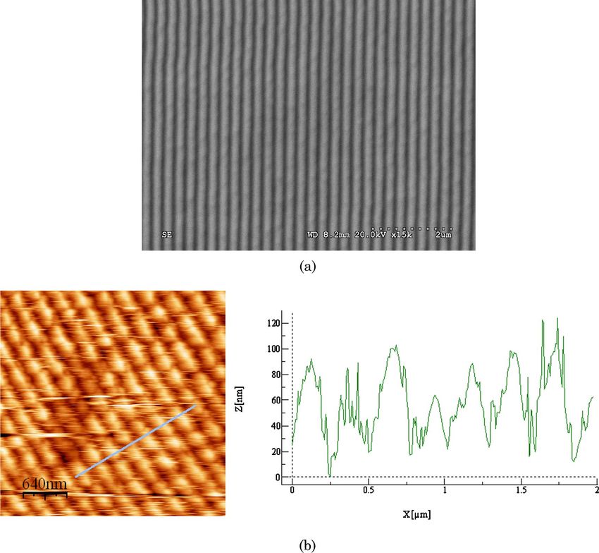
Figure 3 shows a scanning electron microscopy (SEM)
2. Sample Preparation and Experimental Procedures image of the grating recorded over the DCG film and
DFB lasers were made by deposition of polymer an atomic force microscopy (AFM) image of the grat-
active films on top of glass substrates over which ing once transferred to glass. A period of Λ ¼ 270 nm
surface relief gratings were previously recorded by (2 nm) and a depth of 70 nm (15 nm) were obtained.
HL [35,36], followed by conventional reactive ion The diffraction efficiency (η) of the gratings over DCG
beam etching (RIBE). An argon laser operating at and over glass was 28% and 6%, respectively. PS films
364 nm was used to record a light intensity pattern containing 30 wt: % of TPD, deposited by spin coating
over a 700 nm thick spin-coated film of the photosen- over the glass substrates with gratings, formed active
sitive material DCG. The pattern was obtained by waveguides with thicknesses varying between 150
the interference of the direct beam with the beam re- and 300 nm.
flected in a mirror attached to the sample holder (see Figure 4 shows the emission spectra at low and
Fig. 2). An absorbent glass was attached to the back high pump intensities for a DFB device with a
side of the plate with an index matching liquid to 250 nm thick PS/TPD film [Fig. 4(a)], as well as for
avoid backward reflections from the surface of the a sample consisting of a similar film but deposited
glass support. The geometric parameters for grating over a glass substrate without a grating [Fig. 4(b)].
recording were carefully adjusted in order to get a Λ In this latter case, no real lasing takes place since
value close to 270 nm, which satisfies Eq. (1) for no cavity is present. Nevertheless, gain narrowing
m ¼ 2, neff ∼ 1:554 (for a 30 wt: % TPD-doped PS at a certain pump intensity due to ASE is observed,
film), and λ ¼ 420 nm. Relief gratings in the DCG as already discussed in detail in previous works
20 January 2010 / Vol. 49, No. 3 / APPLIED OPTICS 465Fig. 3. Photographs of the relief gratings recorded in (a) a DCG film and (b) in glass after the transfer by RIBE, obtained by SEM and AFM, FMrespectively. [25–27]. By comparing Figs. 4(a) and 4(b), it is clear meter. The emission is strongly polarized, with the that the presence of the grating leads to changes in electric field vector parallel to the DFB grooves. the emission spectra. At low pump intensity, the out- In the case of the film deposited over a glass sub- put spectrum of the DFB device is broad and rather strate without a grating [Fig. 4(b)], the spectrum different than the one obtained with the sample obtained at low pump intensity is similar to that re- without a grating. In accordance with other authors corded in a fluorimeter. This latter one consists of a [34], the modifications observed by the presence of main band with a maximum at 401 nm and a first the grating are attributed to waveguided PL that vibronic peak at 420 nm [27]. Although the emission has been Bragg scattered out of the waveguide at spectrum obtained with the characterization setup an angle normal to the substrate. It is also observed used in this work also shows two peaks, their relative that the spectra of the DFB device exhibit a charac- intensities are somewhat different than the ones ob- teristic dip in the emission intensity at around tained in the fluorimeter, and a slight red shift of the λ ¼ 417 nm, due to an inhibition of the propagation maximum of the main band is observed. These differ- of the waveguided light by the grating. This Bragg ences are simply due to the different geometry used dip can be envisaged as a photonic stop band for to collect the emitted light in the fluorimeter and in waveguided modes [34]. At high pump intensity, the setup for the DFB characterization [27]. Despite DFB lasing occurs at the long-wavelength edge of these slight spectral changes, the most important as- the Bragg dip [see Fig. 4(a)] and a narrow peak dom- pect to consider here is the fact that a dip, similar to inates the emission. This particular device (thickness that observed in Fig. 4(a) for the sample with grating, 250 nm) operates at 418 nm with a linewidth [defined is not observed. With respect to the high pump inten- as the full width at half-maximum (FWHM)] lower sity spectrum, due to ASE, its linewidth is clearly than 2 nm, limited by the resolution of our spectro- reduced (up to around 5 nm) with respect to the 466 APPLIED OPTICS / Vol. 49, No. 3 / 20 January 2010
wavelength side of the stop band. The inhibition of
                                                                    the lasing mode below λBragg can be explained, as sug-
                                                                    gested by other authors [34,40–43], by the fact that
                                                                    the cavity losses for this band edge are lower than
                                                                    for the short-wavelength one, so the long-wavelength
                                                                    mode has a lower threshold [34]. According to this
                                                                    idea, the mechanism dominating laser emission in
                                                                    our DFB lasers would be index modulation. Other
                                                                    authors have attributed the observation of single-
                                                                    mode operation in polymer lasers to the effect of per-
                                                                    iodic gain modulation, rather than index modulation
                                                                    [38,39,41–43]. In those systems, lasing was observed
                                                                    very close to λBragg (inside the stop band) and that was
                                                                    explained in terms of the periodically varying thick-
                                                                    ness of the polymer layers. While periodic gain mod-
                                                                    ulation might be present in our DFB lasers, the fact
                                                                    that the laser mode was found to oscillate on the band
                                                                    edge, and not in the gap, strongly points to a system
                                                                    dominated by index modulation from the permanent
                                                                    grating structure.
                                                                      Figure 5 shows the evolution of the DFB laser in-
                                                                    tensity at λlasing and of the ASE intensity at λASE with
                                                                    the increasing pump intensity, for the samples de-
                                                                    scribed in Fig. 4. For the DFB laser, a nearly expo-
                                                                    nential increase is clearly observed for pump
                                                                    intensities above 6 μJ=pulse, the value identified as
                                                                    the laser threshold. For the sample without grating,
                                                                    a change in slope is not clearly defined; thus, the nu-
                                                                    merical value of the ASE threshold (12 μJ=pulse) was
                                                                    obtained by determining the intensity at which the
                                                                    FWHM of the emitted light decays to half of its
                                                                    maximum value. Here, thresholds are given in en-
                                                                    ergy per pulse units, instead of in power density
                                                                    units, due to the difficulties of properly calculating
Fig. 4. Emission spectra of a TPD-doped PS film deposited on        thresholds in these latter units when using the
glass (a) with and (b) without DFB grating, at low (1 μJ=pulse,     DFB characterization setup. This issue is discussed
dashed curve) and high (20 μJ=pulse, solid curve) pump intensity.
                                                                    in more detail below.
                                                                      The ASE results obtained for the film without
low pump intensity one, and its total output intensity              a grating are similar, in terms of linewidth and
(at 417 nm) is drastically increased. Note that the ob-
tained ASE linewidth is larger than that measured
with the DFB structure (
emission wavelength, to those obtained in the setup
typically used for the ASE characterization [27],
where a stripe of light, instead of a spot, is used to
excite the sample. However, it should be noted that
the thresholds measured in each setup are rather dif-
ferent, mainly due to the different size of the pump
beam. Experiments performed with waveguides
characterized in the typical ASE setup for various
pump stripe lengths (unpublished data), have shown
that the ASE threshold decreases with the length of
the pump stripe, saturating for stripe lengths above
2 mm. Note that, in the typical ASE setup, the size of
the pump stripe is 3:5 mm. Dependencies of the ASE
thresholds with the length of the pump stripe have
also been observed by other authors, in that case
with a poly(phenylene vinylene) derivative [44].
Because in our DFB setup a spot of only 1:3 mm in Fig. 6. Emission spectrum of a second-order DFB laser based on a
diameter is used, the thresholds determined are TPD-doped PS film working at λDFB ¼ 427 nm.
not the optimized ones. Increasing the size of the spot
in order to approximate the conditions of the ASE
setup would result in difficulties in recollecting the This is in contrast with other works published in the
light with the optical fiber. Thus, we decided to ex- literature [37,48], dealing with devices based on ac-
press the thresholds measured in the DFB setup tive films thick enough to support more than one
in energies per pulse and use a similar film without waveguide mode, in which several DFB peaks were
grating to assess the effect of the grating on decreas- observed. Concerning the emission wavelength of the
ing the threshold. All the considerations just stated DFB devices prepared in this work, it has been tuned
justify the lack of coherence in the threshold values from 415 to 427 nm. The lowest thresholds were ob-
found in the literature [2,8,31,34,38,40–47]. Very of- tained for the devices emitting at 418 and at 415 nm,
ten, the ASE thresholds reported for certain materi- with values of 6 and 11 μJ=pulse, respectively. These
als are apparently lower than the laser thresholds wavelengths are close to the vibrational peak of the
measured for the same materials inside a resonant PL spectrum, at which ASE takes place. For devices
cavity. These inconsistencies are often due to the dif- emitting at wavelengths farther away from the ASE
ferent setups used to characterize the properties. wavelength, i.e., λDFB > 420 nm, much larger pump
Moreover, as already discussed in the introduction, intensities were needed in order to obtain laser emis-
for a proper analysis of the potential of different sion. Moreover, a peak due to ASE is also observed.
types of materials for laser purposes, ASE thresh- This is illustrated in Fig. 6 for the device whose laser
olds, rather than laser thresholds, should be com- emission appears at 427 nm. Because of the competi-
pared. In this latter case, it would not be clear tion of both processes, a precise determination of the
whether the differences in threshold are due to the laser thresholds and isolated laser DFB emission
material or to the cavity. was not possible. These results indicate that, with
The tuning of the DFB emission wavelength over these devices, the achievement of DFB laser emis-
the TPD emission spectrum was investigated by pre- sion in a wide range of wavelengths at reasonable
paring and characterizing devices with different film thresholds is limited by the presence of ASE emis-
thicknesses. Results are shown in Table 2. In all sion. Further experiments aiming to clarify the rele-
cases, a single DFB peak was observed, given that vant parameters involved in the interplay between
all the films studied supported one waveguide mode. ASE and DFB are currently being performed.
Table 2. Laser and ASE Performance of 30 wt: % TPD-Doped Polystyrene Films of Various Thicknesses Deposited over Glass with and
without a Second-Order Distributed Feedback Grating
a b c d e
Substrate h λDFB λASE I th-DFB Ith-ASE
Bare glass 250 — 417 12
Glass with DFB grating 160 415 — 11 —
250 418 — 6 —
275 423 417 — —
298 427 417 — —
a
h, film thickness (nm).
b
λDFB , DFB emission wavelength (nm).
c
λASE , ASE emission wavelength (nm).
d
I th-DFB , pump intensity threshold for DFB observation (μJ=pulse).
e
Ith-ASE , pump intensity threshold for ASE observation (μJ=pulse).
468 APPLIED OPTICS / Vol. 49, No. 3 / 20 January 20104. Conclusions 13. M. A. Díaz-García, E. M. Calzado, J. M. Villalvilla, P. G. Boj, J. A.
Quintana, F. Giacalone, J. L. Segura, and N. Martín, “Concen-
Second-order DFB lasers based on PS films doped tration dependence of amplified spontaneous emission in
with 30 wt: % of the blue-emitting and hole- two oligo-(p-phenylenevinylene),” J. Appl. Phys. 97, 063522
transporting organic molecule TPD as gain media (2005).
have been fabricated and their laser properties un- 14. E. M. Calzado, J. M. Villalvilla, P. G. Boj, J. A. Quintana,
der optical pumping have been evaluated. Gratings R. Gómez, J. L. Segura, and M. A. Díaz-García, “Amplified
with a period of 270 nm and a depth of 70 nm were spontaneous emission in polymer films doped with a peryle-
fabricated on glass by holographic lithography and nediimide derivative,” Appl. Opt. 46, 3836–3842 (2007).
subsequent etching methods. Laser thresholds of 15. E. M. Calzado, J. M. Villalvilla, P. G. Boj, J. A. Quintana, R.
6 μJ=pulse and linewidths lower than 2 nm were Gómez, J. L. Segura, and M. A. Díaz-García, “Effect of struc-
measured. The benefits of the presence of the grating tural modifications in the spectral and laser properties of
perylenediimide derivatives,” J. Phys. Chem. C 111, 13595
in improving the laser performance were evidenced (2007).
by comparing with films without gratings, which 16. G. Gigli, G. Barbarella, L. Favaretto, F. Cacialli, and R.
showed ASE thresholds 2 times larger and line- Cingolani, “High-efficiency oligothiopene-based light-emitting
widths of around 5 nm. The emission wavelength diodes,” Appl. Phys. Lett. 75, 439–441 (1999).
of the DFB structures was tuned in the range of 17. N. Johansson, J. Salbeck, J. Bauer, F. Weissörtel, P. Bröms, A.
415–427 nm by changing the thickness of the active Andersson, and W. R. Salaneck, “Solid-state amplified sponta-
film. The fact that laser emission is observed in all neous emission in some spiro-type molecules: A new concept
cases on the long-wavelength edge of the stop band for the design of solid-state lasing molecules,” Adv. Mater. 10,
points to a system dominated by index modulation, 1137 (1998).
18. S. Lattante, M. Anni, M. Salerno, L. Lagonigro, R. Cingolani,
rather than by gain modulation.
G. Gigli, M. Pasini, S. Destri, and W. Porzio, “Optical gain in
The authors acknowledge support from the Spanish fluorenyl-thiophene co-oligomer thin films,” Opt. Mater. 28,
Ministerio de Educación y Ciencia (MEC), the 1072–1075 (2006).
European Community (FEDER) (grants MAT2005- 19. S. Lattante, M. De Giorgi, G. Barbarella, and L. Favaretto,
07369-C03-01 and MAT2008-06648-C02-01) and “Interplay between stimulated emission and singlet-singlet
annihilation in oligothiophene dioxide thin films,” J. Appl.
the University of Alicante (grant VIGROB2005-
Phys. 100, 023530 (2006).
060). We also thank V. Esteve for technical assistance. 20. J. Thomson, M. Anni, S. Lattante, D. Pisignano, R. I. R. Blyth,
G. Gigli, and R. Cingolani, “Amplified spontaneous emission in
Reference
the near infrared from a dye-doped polymer thin film,” Synth.
1. F. Hide, B. J. Schwartz, M. A. Díaz-García, and A. J. Heeger, Met. 143, 305–307 (2004).
“Laser emission from solutions and films containing semicon- 21. T. Maillou, J. Le Moigne, V. Dumarcher, L. Rocha, B. Geffroy,
ducting polymers and titanium dioxide nanocrystals,” Chem. and J.-M. Nunzi, “Oligo (phenyl-ethynylene) as high photolu-
Phys. Lett. 256, 424–430 (1996). minescence quantum yield materials and its distributed
2. F. Hide, M. A. Diaz-Garcia, B. J. Schwartz, M. Andersson, Q. feedback (DFB) laser emission properties in thin films,”
Pei, and A. J. Heeger, “Semiconducting polymers: a new class Adv. Mater. 14, 1297–1301 (2002).
of solid-state laser materials,” Science 273, 1833–1836 (1996). 22. X. Zhu, D. Gindre, N. Mercier, P. Frère, and J.-M. Nunzi, “Am-
3. N. Tessler, G. J. Denton, and R. H. Friend, “Lasing from con- plified stimulated emission from a needle-like single crystal of
jugated-polymer microcavities,” Nature 382, 695–697 (1996). an end-capped fluorene/phenylene co-oligomer,” Adv. Mater.
4. M. D. McGehee and A. J. Heeger, “Semiconducting (conju- 15, 906–909 (2003).
gated) polymers as materials for solid-state lasers,” Adv. 23. A. Costela, I. García-Moreno, and R. Sastre, “Polymeric solid-
Mater. 12, 1655–1668 (2000) and references therein. state dye lasers: recent developments,” Phys. Chem. Chem.
5. N. Tessler, “Lasers based on semiconducting organic materi- Phys. 5, 4745–4763 (2003).
als,” Adv. Mater. 11, 363–370 (1999) and references therein. 24. W. Holzer, A. Penzkofer, and H.-H. Hörhold, “Travelling-wave
6. I. D. W. Samuel and G. A. Turnbull, “Organic semiconductor lasing of TPD solutions and neat films,” Synth. Met. 113,
lasers,” Chem. Rev. 107, 1272–1295 (2007) and references 281–287 (2000).
therein. 25. M. A. Díaz-García, E. M. Calzado, J. M. Villalvilla, P. G. Boj, J.
7. F. J. Duarte and L. W. Hillman, eds., Dye Laser Principles with A. Quintana, and M. G. Kuzyk, “TPD-based blue organic
Applications (Academic, 1990). lasers,” J. Nonlinear Opt. Phys. Mater. 13, 621 (2004).
8. G. A. Turnbull, P. Andrew, W. L. Barnes, and I. D. W. Samuel, 26. E. M. Calzado, J. M. Villalvilla, P. G. Boj, J. A. Quintana, and
“Operating characteristic of a semiconducting polymer laser M. A. Díaz-García, “Tuneability of amplified spontaneous
pumped by a microchip laser,” Appl. Phys. Lett. 82, 313–315 emission through control of the thickness in organic-based
(2003). waveguides,” J. Appl. Phys. 97, 093103 (2005).
9. A. E. Vasdekis, G. E. Town, G. A. Turnbull, and I. D. W. Samuel, 27. E. M. Calzado, J. M. Villalvilla, P. G. Boj, J. A. Quintana, and
“Fluidic fibre dye laser,” Opt. Express 15, 3962–3967 (2007). M. A. Díaz-García, “Concentration dependence of amplified
10. A. E. Vasdekis, S. A. Moore, A. Ruseckas, T. F. Krauss, I. D. W. spontaneous emission in organic-based waveguides,” Org.
Samuel, and G. A. Turnbull, “Silicon based organic semi- Electron. 7, 319 (2006).
conductor laser,” Appl. Phys. Lett. 91, 051124 (2007). 28. K. Bando, T. Nakamura, and Y. Masumoto, “Origin of the
11. M. D. McGehee, R. Gupta, S. Veenstra, E. K. Miller, M. A. amplified spontaneous emission from thiophene/phenylene
Díaz-García, and A. J. Heeger, “Amplified spontaneous co-oligomer single crystals: towards co-oligomers lasers,” J.
emission from photopumped films of a conjugated polymer,” Appl. Phys. 99, 013518–013521 (2006).
Phys. Rev. B 58, 7035–7039 (1998). 29. W. Xie, Y. Li, F. Li, F. Shen, and Y. Ma, “Amplified spontaneous
12. M. A. Díaz-García, S. Fernández De Avila, and M. G. Kuzyk. emission from cyano-substituted oligo (p-phenylene vinylene)
“Dye-doped polymers for blue organic diode lasers,” Appl. single crystal with very high photoluminescence efficiency,”
Phys. Lett. 80, 4486–4488 (2002). Appl. Phys. Lett. 90, 141110 (2007).
20 January 2010 / Vol. 49, No. 3 / APPLIED OPTICS 46930. J. C. Ribierre, G. Tsiminis, S. Richardson, G. A. Turnbull, I. D. 40. G. A. Turnbull, P. Andrew, W. L. Barnes, and I. D. W. Samuel,
W. Samuel, H. S. Barcena, and P. L. Burn, “Amplified sponta- “Photonic mode dispersion of a two-dimensional distributed
neous emission and lasing properties of bisfluorene-cored feedback polymer laser,” Phys. Rev. B 67, 165107 (2003).
dendrimers,” Appl. Phys. Lett. 91, 081108 (2007). 41. G. Heliotis, R. Xia, and D. D. C. Bradley, “Blue, surface-
31. R. Xia, G. Heilotis, Y. Hou, and D. D. C. Bradley, “Fluorene- emitting distributed feedback polyfluorene lasers,” Appl.
based conjugated polymer optical gain media,” Org. Electron. Phys. Lett. 83, 2118–2121 (2003).
4, 165–177 (2003). 42. S. Riechel, U. Lemmer, J. Feldmann, T. Benstem, W. Kowalsky,
32. L. A. Coldren and S. W. Corzine, Diode Lasers and Photonic U. Scherf, A. Gombert, and V. Wittwer, “Laser modes in organ-
Integrated Circuits (Wiley 1995). ic solid-state distributed feedback lasers,” Appl. Phys. B. 71,
33. M. D. McGehee, M. A. Díaz-García, F. Hide, R. Gupta, E. K. 897–900 (2000).
Miller, D. Moses, and A. J. Heeger, “Semiconducting polymer 43. C. Bauer, H. Giessen, B. Schnabel, E. B. Kley, C. Schmitt, U.
distributed feedback laser,” Appl. Phys. Lett. 72, 1536–1538 Scherf, and R. F. Mahrt, “A surface-emitting circular grating
(1998). polymer laser,” Adv. Mater. 13, 1161–1164 (2001).
34. G. A. Turnbull, P. Andrew, M. J. Jory, W. L. Barnes, and I. D. W. 44. I. Silvestre, P. W. B. Marques, M. Valadares, and L. A. Cury,
Samuel, “Relationship between photonic band structure and “Gain coefficient method for amplified spontaneous emission
emission characteristic of a polymer distributed feedback in thin waveguided film of a conjugated polymer,” Appl. Phys.
laser,” Phys. Rev. B 64, 125122 (2001). Lett. 93, 163307 (2008).
35. J. A. Quintana, P. G. Boj, J. Crespo, J. A. Vallés-Abarca, and J. 45. N. Tsutsumi, T. Kawahira, and W. Sakai, “Semiconducting
M. Villalvilla, “Diffraction gratings in dry developed dichro- polyfluorenes as materials for solid-state polymer lasers
mated gelatin films,” Thin Solid Films 317, 343–346 (1998). across the visible spectrum,” Appl. Phys. Lett. 83, 2533–2535
36. J. M. Villalvilla, J. Crespo, J. A. Quintana, C. Santos, and J. A. (2003).
Vallés-Abarca, “Oxygen ECR stream etching of dichromated 46. R. Xia, G. Heliotis, and D. D. C. Bradley, “Amplified sponta-
gelatin films,” Thin Solid Films 317, 340–342 (1998). neous emission and distributed feedback lasing from a conju-
37. V. Dumarcher, L. Rocha, C. Denis, C. Fiorini, J.-M. Nunzi, F. gated compound in various polymer matrices,” Synth. Met.
Sobel, B. Sahraoui, and D. Gindre, “Polymer thin-film distrib- 140, 117–120 (2004).
uted feedback tunable lasers,” J. Opt. A Pure Appl. Opt. 2, 47. R. Xia, G. Heliotis, and D. D. C. Bradley, “Fluorene-based poly-
279–283 (2000). mer gain media for solid-state laser emission across the full
38. G. Heliotis, R. Xia, G. A. Turnbull, P. Andrew, W. L. Barnes, I. visible spectrum,” Appl. Phys. Lett. 82, 3599–3601 (2003).
D. W. Samuel, and D. D. C. Bradley, “Emission characteristics 48. V. Trabadelo, A. Juarros, A. Retolaza, M. G. Ramírez, V.
and performance comparison of polyfluorene lasers with Navarro-Fuster, J. M. Villalvilla, P. G. Boj, J. A. Quintana,
one- and two-dimensional distributed feedback,” Adv. Funct. and M. A. Díaz-García, “Highly photostable solid-state organic
Mater. 14, 91–97 (2004). distributed feedback laser fabricated via thermal nanoimprint
39. H. Kogelnik and C. V. Shank, “Couple-wave theory of distrib- lithography,” Microelectron. Eng., doi:10.1016/j.mee.2009.
uted feedback lasers,” J. Appl. Phys. 43, 2327–2335 (1972). 11.142 (in press).
470 APPLIED OPTICS / Vol. 49, No. 3 / 20 January 2010You can also read