CETAC ASX-112FR Autosampler - Operator's Manual
←
→
Page content transcription
If your browser does not render page correctly, please read the page content below
CETAC ASX-112FR Autosampler

Operator’s Manual
Manual Part Number 480159 Rev 4
COPYRIGHT                                       TRADEMARK ACKNOWLEDGEMENTS
© 2008-2014 Teledyne Technologies               Windows is a registered trademark of
Incorporated. All rights reserved.              Microsoft Corporation in the United States and
                                                other countries.
480159 Rev 4 , January, 2014
                                                PharMed and Tygon are registered
Teledyne CETAC Technologies authorizes its      trademarks of Saint-Gobain Performance
customers to reproduce, transmit, or store      Plastics.
this document in its entirety, including this
page, for the express purpose of installing,    All other marks are the property of their
operating, or maintaining the product           respective owners.
described herein.

Teledyne CETAC Technologies
Customer Service & Support
14306 Industrial Road
Omaha, Nebraska 68144, USA
Phone     (800) 369-2822 (USA only)
Phone     (402) 733-2829
Fax       (402) 733-1932
E-mail    custserv@cetac.com
REVISIONS
Teledyne CETAC Technologies strives to
provide the scientific community with an
unparalleled combination of effective
technology and continuing value. Modular
upgrades for existing instruments will
continue to be a prime consideration as
designs progress.
Teledyne CETAC Technologies reserves the
right to revise this document and/or improve
products described herein at any time without
notice or obligation. Warranty registration
entitles the named owner exclusively to
manual change pages/new editions as they
are published.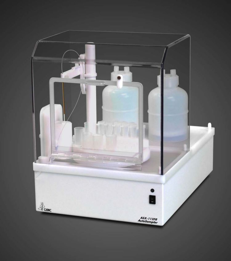
Contents
1   Introduction .............................................................................................................. 7
    Overview.................................................................................................................................... 7
    About This Book ..................................................................................................................... 7
        Who Should Read This Book ...................................................................................... 7
    Autosampler Configuration Options ............................................................................. 8
    Autosampler Standard Components ............................................................................. 9
    Additional Equipment Required ...................................................................................12
    Optional Accessories ..........................................................................................................12
    Chemical Compatibility .....................................................................................................14
    Where to Go for More Information ..............................................................................14
2   Preparing for Installation ................................................................................. 15
    Choosing a Location ............................................................................................................15
       Space Requirements.................................................................................................... 15
       Work Surface Requirements .................................................................................... 16
       Rinse Solution Requirements................................................................................... 16
       Liquid Waste Routing Requirements ................................................................... 16
       Power Requirements................................................................................................... 16
    Unpacking the Autosampler ...........................................................................................17
3   Installing the Autosampler ............................................................................... 19
        Overview .......................................................................................................................... 19
    Mounting the Sample Probe Assembly ......................................................................20
    Connecting the Rinse Station..........................................................................................22
        Peristaltic Pump Configuration.............................................................................. 23
        Gas Displacement Pump Configuration .............................................................. 25
        Argon Gas Supply for Gas Displacement Pump ................................................ 26
    Assemble and Place the Sample Rack and Vials .....................................................31
        Short Rack Configuration ......................................................................................... 31
        Tall Rack Configuration ............................................................................................ 32
    Connecting the Autosampler to the Power Supply ...............................................34
    Connecting the Autosampler to an Analytical Instrument ................................35
    Connect the ASX-112FR Autosampler to the Host Computer ..........................35
    Establishing an RS-232 Serial Communications Interface ................................36
    Establishing a USB Communications Interface ......................................................37
    Establishing an IEEE Communications Interface ..................................................41
    ASX-112FR Tray Files ........................................................................................................41
4   Verifying Installation .......................................................................................... 43
    Testing the Communications Interface ......................................................................43
    Checking the Autosampler Components ...................................................................44
    Testing the Sample Probe ................................................................................................44

                                                                                                                                              3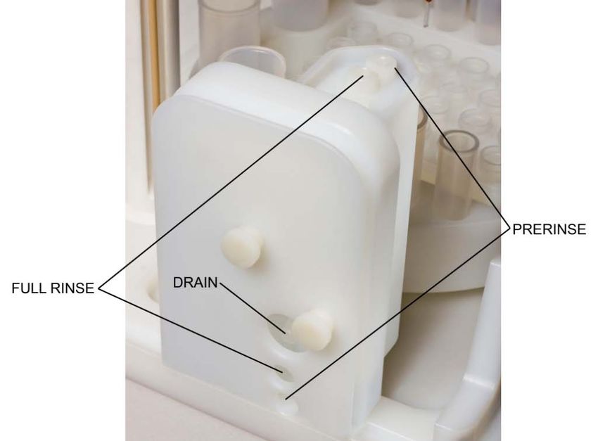
ASX-112FR Autosampler Operator’s Manual
Contents

5   Using the Autosampler ....................................................................................... 47
    Establishing Optimal Operating Conditions ............................................................ 47
        Creating the Lab Environment ............................................................................... 47
        Replacing Auto Sampler Components ................................................................. 48
        Purchasing Supplies ................................................................................................... 48
    Arranging the Sample Vial Racks ................................................................................. 49
    Starting the Autosampler................................................................................................. 49
    Shutting Down the Autosampler .................................................................................. 50
    Flushing the Rinse Station and Flow Path ................................................................ 50
    Reconfiguring the Autosampler Sample Height .................................................... 51
    Reconfiguring the Autosampler ICP-MS Personality........................................... 52
6   Maintaining the Autosampler .......................................................................... 53
    Cleaning the Autosampler ............................................................................................... 53
        Routine External Cleaning ....................................................................................... 53
        Thorough Cleaning ..................................................................................................... 54
    Checking for Leaks .............................................................................................................. 55
    Replacing the Rotary Tray ............................................................................................... 55
    Replacing the Rinse Station ............................................................................................ 56
    Replacing Peristaltic Pump Tubing ............................................................................. 58
    Replacing the Sample Probe ........................................................................................... 58
    Replacing the Rinse Tubing ............................................................................................ 59
    Spare Parts ............................................................................................................................. 60
        Peristaltic Pump Tubing ........................................................................................... 60
        Sample Probes............................................................................................................... 60
        C-Flow PFA Nebulizers .............................................................................................. 60
        Vials................................................................................................................................... 60
7   Troubleshooting the Autosampler ................................................................. 61
    Power System Problems .................................................................................................. 61
    Communications Interface Problems ......................................................................... 62
        RS-232 Serial Cable Problems ................................................................................ 62
        USB Cable Problems.................................................................................................... 62
        Software Configuration Problems ........................................................................ 63
    Alignment Problems .......................................................................................................... 63
    Returning the Product to CETAC for Service .......................................................... 64
        Shipping the Product.................................................................................................. 64
        Product Warranty Statement ................................................................................. 64
        Returned Product Procedures ................................................................................ 65
        Returned Product Warranty Determination .................................................... 66
8   Operating a CETAC Autosampler Using a Terminal Program .............. 67
    Using C-Term™ ..................................................................................................................... 67
        Starting C-Term ........................................................................................................... 67
        Overview of the C-Term Window ........................................................................... 68
        Configuring C-Term .................................................................................................... 69
        Setting Preferences ..................................................................................................... 70
    Using HyperTerminal ........................................................................................................ 70
    Autosampler Commands .................................................................................................. 74
9   Safety and Regulatory Information................................................................ 75
    Characteristics ...................................................................................................................... 75
       Environmental Characteristics .............................................................................. 75

4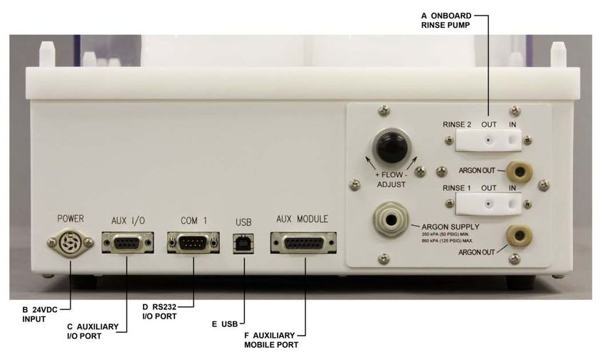
ASX-112FR Autosamplers Operator’s Manual
                                                                                                                                Contents

          Electrical Characteristics.......................................................................................... 76
      Safety Notices ........................................................................................................................77
          Power Cord Set Requirements ................................................................................ 77
          Power Cord Safety Maintenance ............................................................................ 77
          Mains Disconnect ......................................................................................................... 77
          Cleaning Instructions ................................................................................................. 78
          Mechanical Hazards ................................................................................................... 78
          Operating Environment............................................................................................. 79
          Explanation of Caution and Warning Notices .................................................. 80
      Avertissements en Français ............................................................................................81
      Electromagnetic Interference ........................................................................................82
      Explanation of Regulatory Marks .................................................................................82
10 Glossary ................................................................................................................... 83

                                                                                                                                          5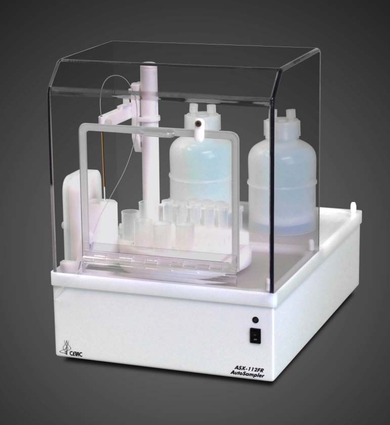
ASX-112FR Autosampler Operator’s Manual
Contents

This page is intentionally blank.

6
1 Introduction
Overview
The CETAC ASX-112FR autosampler is designed to be sturdy, reliable, and easy
to use. It provides automated sample introduction that enables you to perform
other tasks while the autosampler runs. The ASX-112FR autosampler
automatically introduces up to 96 samples when fully loaded. It contains a
microprocessor that allows sequential or random sampling, providing
flexibility.
The autosampler is typically interfaced to and controlled by the ICP-MS
instrument host computer using a serial or USB connection.
The ASX-112FR offers a small footprint to conserve bench space, a short
sample path to preserve valuable sample, and a protective cover to prevent
sample contamination. The dual flowing rinse station prevents carry over to
ensure sample integrity. The ASX-112FR is both contamination and corrosion
resistant and offers a completely inert flow path.
The ASX-112FR can be conveniently placed on top of the CETAC Aridus II™
Desolvating Nebulizer System. The Aridus II™ is commonly used for signal
enhancement/interference reduction for ICP-MS. Applications include
corrosive, limited-volume samples for geology and semiconductors.
About This Book
This document describes the procedures for installing, using, and maintaining
the autosampler. It also provides information about troubleshooting minor
problems and describes the design of the autosampler.
This manual covers the following products:
CETAC ASX-112FR
Who Should Read This Book
The primary audience for this manual consists of analytical chemists and lab
technicians. To use this manual effectively, you should have a basic knowledge
7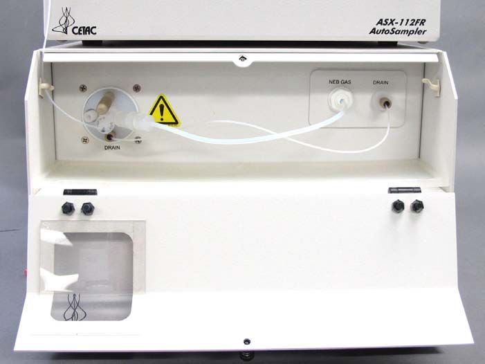
ASX-112FR Autosampler Operator’s Manual
          Chapter 1: Introduction

          of chemistry, a basic knowledge of electronic sampling equipment, at least a
          beginning level of computer experience, and working knowledge of the
          analytical instrument used with the autosampler.

          CHEMICAL INJURY HAZARD
WARNING   The autosampler is intended for use only by qualified operators who have
          been trained in safe laboratory practices. Make sure you know the hazards
          associated with all of the chemicals you are using, and take the appropriate
          precautions. Exposure to laboratory chemicals may result in serious injury.

          Autosampler Configuration Options
           The ASX-112FR is very configurable making it ideal for use in multiple
          applications. Three models are available. The standard model comes with a
          polypropylene rinse station controlled by a peristaltic pump. A second model
          comes with a polypropylene rinse station controlled by a gas displacement
          pump, which uses compressed gas to push the rinse solutions through the
          rinse station. A third model is equipped with a PFA rinse station and a gas
          displacement pump for ultra-clean applications.
          All three models have the option to be selected in either a tall or short
          configuration. The height configuration restricts the choice of racks to be
          either tall—BelArt half racks (with 7 mL or 14 mL vials) or short—CETAC
          racks for small samples (with 0.5 mL, 1.0 mL, 1.5 mL or 2 mL vials). The rinse
          station is also configured in either a tall or short version.
          Two probe sizes are offered: 0.010” (0.25 mm) ID and 0.035” (0.89 mm) ID.
          The 0.035” ID is expected to be the standard with the 0.010” ID designed for a
          low-flow (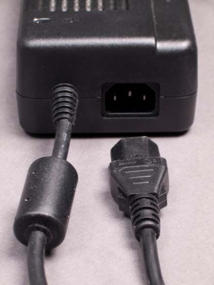
ASX-112FR Autosamplers Operator’s Manual
                                                     Chapter 1: Introduction

Autosampler Standard Components

Figure 1-1. ASX-112FR Autosampler—Front View

Figure 1-2. ASX-112FR Autosampler—Side View.

                                                                         9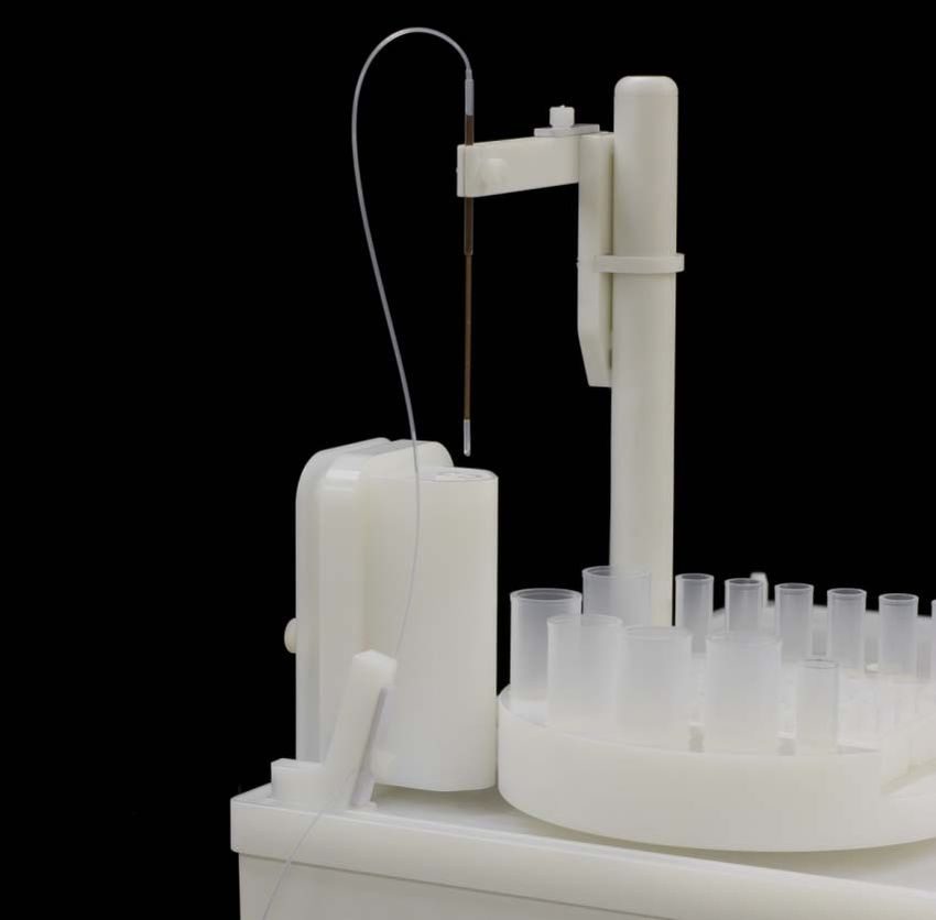
ASX-112FR Autosampler Operator’s Manual
Chapter 1: Introduction
The following components are located on the front of the autosampler and are
shipped with the autosampler. Each lettered item corresponds with a callout in
Figure 1-2.
A Rotary Tray. The rotary tray has 14 standard positions and a rectangular
center cavity, which holds one sample rack in place.
B Sample Rack Location. The ASX-112FR includes one sample rack. Rack
choices include short or tall rack configurations. A keyed interface plate is
required to use the short racks. The tall racks are placed directly in the rotary
tray with no interface plate required. The appropriate sample vials must be
used for each rack, and the host computer’s software must be configured for
that particular rack layout and number of positions. The identification
designations are shown in the host computer's software – if the software does
not include a specific reference for the ASX-112FR, a reference for the older
model ASX-100 may be applicable with the ASX-112FR tray files.
Short – CETAC Racks:
• 24 position, 1.5 mL or 2.0 mL vials
• 48 position, 0.5 mL vials
• 96 position, 1.0 mL vials
Tall – Bel-Art Half Racks:
• 30 position, 14 mL vials
• 42 position, 7 mL vials
C Standards Vials. Up to 14 standards positions are available with the
autosampler:
Short Tall
9 – 4 mL vials 9 – 10 mL vials
5 – 20 mL vials 5 – 30 mL vials
D Dual Flowing Rinse Station. The dual rinse station is located next to the
sample tray. It comes with tubing used to connect the rinse station to two
separate rinse sources (deionized water pre-rinse and acid full rinse) and the
waste container. The rinse station is provided in either a short or tall version
to match the rack choice.
E Rinse Alignment Block.
F Z-Drive Assembly.
G Y-Arm Assembly. The Y-arm is attached to the Z-drive assembly in one of two
mounting locations depending upon the choice for short or tall function.
H Sample Probe. Sample probes are constructed of fluoropolymer tubing
reinforced with a carbon fiber or polyimide tube to provide strength and
maintain straightness. Available probe sizes include 0.010” (0.25 mm) ID and
0.035” (0.89 mm) ID. If the ASX-112FR is used with the Aridus II, then the
uptake line of the C-Flow PFA nebulizer (equipped with a polyimide support
tube) is used as the sample probe.
I Power Switch. Rocker switch, single pole-single throw, 16 amp.
10ASX-112FR Autosamplers Operator’s Manual
Chapter 1: Introduction
J Power/Status LED. Green light should be lit when the power is on and the
autosampler is ready to operate.
K Cover. The cover door may be opened (using a bar latch) during operation
without interrupting the sampling sequence.
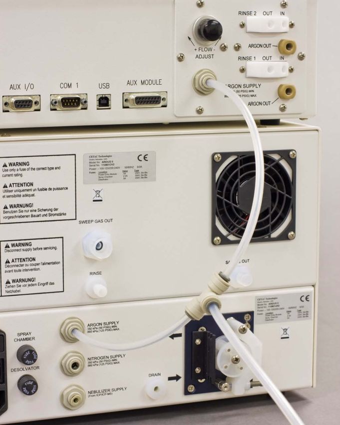
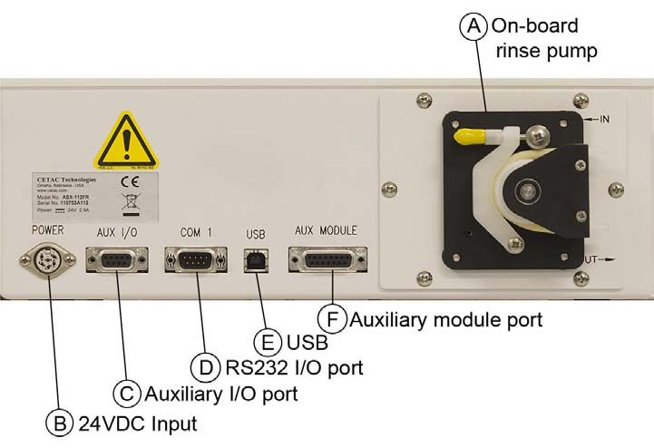
The following standard components are located on the back of the ASX-112FR
and are shipped with the autosampler. Each lettered item corresponds with a
callout in either Figure 1-3 or Figure 1-4.
Figure 1-3. ASX-112FR Autosampler-Back View Gas Displacement Pump
Model.
Figure 1-4. ASX-112FR Autosampler-Back View Peristaltic Pump Model.
A On-Board Rinse Pump. The on-board rinse pump may be either a peristaltic
pump or a gas displacement pump. In either configuration, the pump is
11ASX-112FR Autosampler Operator’s Manual
Chapter 1: Introduction
located in the upper right-hand corner on the back of the autosampler. The
pump moves the rinse solutions from two rinse sources through the flowing
rinse station.
B 24VDC Input. The six-pin jack for 24VDC input from the power module.
C Auxiliary I/O Port. The auxiliary I/O port detects switch closures or can
trigger devices that can be operated from switch closure (TTL) event triggers.
It can also be used to control external devices that require +24VDC. An
example of such a device is the QuickWash Accessory that can be used with the
Aridus II™ Desolvating Nebulizer System.
D One RS-232 Serial I/O Port-COM1. The serial port is located in the center of
the lower back of the autosampler. The COM1 port is the communications
interface between the ASX-112FR and the analytical instrument’s host
computer.
E USB Option. The ASX-112FR comes standard with a USB port. This port can
be used to interface the ASX-112FR with the host computer.
F Auxiliary Module Port. The auxiliary module port is included for possible
addition of an external device that requires +24VDC.
There are two sets of dipswitches located on the bottom of the autosampler.
The five-position dipswitch defines normal operating mode or rabbit
programming mode. The first three switches of the eight-position dipswitch
define the ICP-MS interface and switch #6 controls whether the autosampler
functions in the Tall or Short mode: 1 = Tall (Bel-Art racks), 0 = Short (CETAC
racks).
The following standard components are also shipped with the ASX-112FR:
External Desktop Power Supply. The input rating is AC 100V-240V, 1.9 A,
with an output of DC 24V, maximum 3.3 A.
Serial Interface Kit. The kit includes DB9F port adapters for host computers
with normal AT-style DTE serial ports, and a 1.828-meter modular cable.
Additional Equipment Required
In addition to the provided equipment, you will need:
A host computer which has been configured with the ICP-MS software. This
computer must have an additional free USB or serial ports beyond the ports
required to control the autosampler, spectrometer, and other system
components.
Optional Accessories
If you are doing a specialized type of analysis or are connecting the ASX-112FR
to a host computer that uses a non-RS-232 communications protocol, you may
need optional accessories in addition to the standard components included
with the autosampler. The following accessories are available for the ASX-
112FR:
12ASX-112FR Autosamplers Operator’s Manual
Chapter 1: Introduction
IEEE-488 Interface Kit. The kit includes an RS-232/IEEE-488 converter
box, an IEEE-488 cable, a power cord, and instructions. It is used to convert
an IEEE communications protocol to a serial protocol.
C-Flow PFA Nebulizer. The C-Flow Nebulizer is a molded, fixed-capillary
style PFA concentric nebulizer for the introduction of low-volume (< 1mL)
samples to an ICP-MS. The inert PFA construction allows the introduction
of all acids (including hydrofluoric acid), alkalis and organic solvents. It
features a standard 6mm diameter tip for easy installation to most spray
chambers.
QuickWash Fast Washout Accessory. The QuickWash Fast Washout
Accessory can be used with the Aridus II™ Desolvating Nebulizer System
and the ASX-112FR Autosampler. The ASX-112FR can trigger the
QuickWash to begin a rinse cycle for the Aridus II™ PFA spray chamber.
Alternate Rinse Height Kit. Alternate rinse kits are available as spares to
convert a short configuration into a tall and vice versa.
Alternate Sample Rack Kits. Additional rack kits are available as spares to
run samples of varying volumes.
Alternate Sample Probes. Alternate sample probes are available as
spares.
NOTE:
Contact Teledyne CETAC Technologies if you need additional accessories not
listed, need added features to integrate the autosampler into your analytical
system, or have unique requirements. Research and development of new
features and accessories for the autosampler, often inspired by customer
requests, is a continuing activity at Teledyne CETAC Technologies.
13ASX-112FR Autosampler Operator’s Manual
Chapter 1: Introduction
Chemical Compatibility
Autosampler components are made of Ultra-High Molecular Weight
Polyethylene (UHMW-PE) and Polyethylene Terephthalate. The base is made
from a high-strength aluminum alloy with an epoxy powder coating finish. The
sample racks are made from UHMW-PE or polypropylene and are protected
from airborne contaminants and operator interference by a polycarbonate
cover. Sample vial choices include PFA and polypropylene.
The ASX-112FR operates reliably under a wide variety of conditions.
Components in the sample flow path are made of FEP or PFA. When these
inert, non-metallic materials are used at temperatures less than 135°C, they
can withstand repeated exposure to the following substances:
Predominantly aqueous solutions of strong acids (less than 40%)
Common organic solvents such as acetone, alcohols, ethyl acetate,
Methylethylketone (MEK), petroleum oils and derived fuels,
tetrachloroethylene, toluene, kerosene and xylene.
CAUTION DAMAGE FROM CHEMICAL EXPOSURE
Prolonged or repeated exposure to temperatures greater than 135°C and to the
following substances can cause failure of the flow path components:
• Solutions of concentrated acids (greater than 40%).
• Solutions of concentrated bases (greater than 10% potassium, ammonium, or
sodium hydroxides).
• Partially halogenated hydrocarbons or extremely aggressive organic solvents
(chloroform, methylene dichloride, 1,1,2-trichloroethane).
CHEMICAL HAZARD
WARNING Do not use the autosampler with substances which could pose a hazard of
serious injury to the operator if spilled or injected, such as biological
substances or formic acid.
Where to Go for More Information
In addition to this manual, you can refer to the following resources:
New versions of this manual may be available under “Service and Support”
on CETAC’s Web site: www.cetac.com
ASX-112FR Autosampler Spare Parts Catalog, available on the CD-ROM or
under "Parts" on CETAC’s Web site.
Teledyne CETAC Technologies Customer Service and Support:
Phone: 1 (800) 369-2822 (USA only)
1 (402) 733-2829
Fax: 1 (402) 733-1932
E-mail: custserv@cetac.com
The software manual for the ICP-MS instrument you are using.
142 Preparing for
Installation
Installing the autosampler requires preparation. Before you install the
autosampler, you should evaluate the physical arrangement of the laboratory
to choose a suitable location. Once you choose a location, you must carefully
unpack the autosampler prior to beginning the installation.
This chapter discusses what requirements must be met when you choose a
location. It also describes how to unpack the equipment before installation.
Choosing a Location
Choosing a location for the autosampler involves evaluating the lab
environment for the availability of space, liquid waste routing and power. For
the system to function optimally, the location you select must meet specific
requirements associated with each of these items. The following sections
discuss space, water, and power requirements.
Space Requirements
Most analytical applications benefit from utilizing the shortest sample flow
path. Therefore, you should place the autosampler in close proximity to the
analytical instrument. The recommended footprint for the autosampler is
shown in the following table.
Dimensions Recommended Footprint
Height 44 cm (17.3") 55 cm (22")
Width 34 cm (13.4") 44 cm (17")
Depth 52 cm (20.5") 59 cm (23")
Weight 14.1 kg (31 lbs)
Table 1: Physical Characteristics – ASX-112FR
The weight shown is that of the autosampler itself, without the desktop power
supply or other accessories.
15ASX-112FR Autosampler Operator’s Manual
Chapter 2: Preparing for Installation
Allow at least 5 cm behind the autosampler for power cord and
communication cable egress. Always position the equipment so that it is easy
to disconnect the power cord.
Work Surface Requirements
The ASX-112FR can be conveniently placed on top of the CETAC Aridus II™
Desolvating Nebulizer System. Otherwise, the autosampler must be placed on
a sturdy countertop or table. Do not place the autosampler on a wheeled cart
or folding table.
During operation, the autosampler produces both vertical and horizontal
forces. If the work surface is allowed to shake or wobble, the autosampler may
“walk” across the surface, liquids may spill, or data quality may be affected.
Rinse Solution Requirements
For most applications, 2% nitric acid (HNO3) (v/v) is used as the primary rinse
agent and deionized water is used as the pre-rinse agent in the ASX-112FR.
Place the rinse agent source(s) within two meters of the ASX-112FR.
CHEMICAL INHALATION AND BURN HAZARD
WARNING Observe all necessary safety precautions when handling nitric acid (HNO 3 )
solutions. Wear appropriate personal protective equipment, including face
shield or goggles, gloves, and a laboratory coat, and ensure that
engineering controls (such as ventilation systems) are operating properly.
Liquid Waste Routing Requirements
Ensure that there is a liquid waste receptacle within two meters of the
autosampler. The waste receptacle inlet should be 30 to 60 centimeters lower
than the autosampler rinse station outlet and set up so that the rinse drain
tubing drops directly into the waste receptacle with no coiling and without
being submerged below the liquid level of the waste receptacle.
CAUTION SUBMERGED DRAIN TUBING MAY CAUSE EQUIPMENT DAMAGE
Ensure that the rinse drain tubing is not submerged in the waste liquid. If the
tubing is submerged, waste liquid can back up in the rinse station, flooding the
sample tray and potentially damaging the electronics.
Power Requirements
The autosampler is powered by the supplied external desktop "brick" power
supply. Place the autosampler within 1.2 meters of a power outlet.
SHOCK AND FIRE HAZARD
WARNING Use only the provided power supply. The power supply must be plugged
into an outlet which has a protective ground connection.
The autosampler is intended to operate from DC power supplied through the
provided power supply. The power supply is provided power through an AC
power source that will not apply more than 240VAC between the supply
conductors and ground. A protective ground connection by way of the
grounding connector in the power cord is required for safe operation.
16ASX-112FR Autosamplers Operator’s Manual
Chapter 2: Preparing for Installation
Ensure that you position the autosampler so that the location where the power
supply cord plugs into it is easily accessible (is not blocked) and it can be
quickly disconnected if needed. In case of hazard, the autosampler should be
disconnected from the power source.
The power supply socket is on the back of the autosampler (see Figure 1-4 on
page 11). Connect the power supply to the autosampler first and then connect
a line cord to the power supply. Do not apply power to the power supply until
ready to operate the autosampler.
Unpacking the Autosampler
LIFTING HAZARD
WARNING The autosampler may be awkward to lift. Incorrect lifting technique may
cause personal injury. Use caution when lifting the autosampler.
Inspect external packaging upon receipt for signs of shipping damage. Inspect
all items during unpacking and notify the carrier immediately of any concealed
damage. Check for any kinked or bent tubing.
If the system is shipped or removed from storage during cold weather, allow
the packaged equipment to equilibrate to room temperature before opening
and exposing to warm, humid air. It is usually sufficient to provide four to eight
hours for this purpose.
CAUTION EQUIPMENT DAMAGE FROM CONDENSATION
If condensation forms on or inside the autosampler, allow it to dry thoroughly
before connecting it to a power source and operating it. Failure to do so may cause
equipment damage.
Remove the packing checklist from the shipping container, and check off items
against it. Leave accessories in the packing until you are ready to install them.
NOTE
Keep the factory packaging for use in case the product ever needs to be
returned or shipped to another location.
17ASX-112FR Autosampler Operator’s Manual Chapter 2: Preparing for Installation This page is intentionally blank. 18
3 Installing the
Autosampler
The autosampler is designed for easy installation. Installation consists of two
parts: assembling the autosampler and connecting it to the host analytical
instrument.
The autosampler can be installed with minimal effort; no tools are required.
You can remove thumbscrews with tools if necessary, but do not tighten them
with anything other than your fingers.
Overview
To install the autosampler, you must complete the following tasks. Each of
these tasks will be discussed in detail later in this chapter.
Mount the sample probe assembly.
Connect the rinse station.
Assemble and place the sample racks and standards vials.
Establish external connections.
Connect the ASX-112FR autosampler to the host computer.
Ensure the power switch is off and the power cord is unplugged before
WARNING proceeding with installation. If the power is left on, motors may move
unexpectedly and cause injury.
19ASX-112FR Autosampler Operator’s Manual Chapter 3: Installing the Autosampler Mounting the Sample Probe Assembly Mounting the sample probe assembly on the autosampler is the first task in assembling the ASX-112FR. However, prior to mounting the probe, the installation of the Y-arm should be confirmed to be compatible with the height of the racks intended for use. Figure 3-1 shows three sets of mounting holes provided for height options for the Y-arm. If the autosampler is intended to run with half Bel-Art racks and tall standards in the tall configuration, make sure the Y-arm is mounted in the top most mounting location. If the autosampler is intended to run with the CETAC short racks and short standards in the short configuration, make sure the Y-arm is mounted in the lowest mounting position. The center mounting position may also be used for the desired probe Z-axis travel. Figure 3-1. Y-Arm Mounting Positions. 20
ASX-112FR Autosamplers Operator’s Manual
                                                    Chapter 3: Installing the Autosampler

    Figure 3-2. Sample Probe Assembly Installation.
    Figure 3-2 illustrates the sample probe assembly installation. The instructions
    below can be used for the standard probe or the uptake capillary of the C-Flow
    PFA nebulizer.

1   Insert the probe into the Y-arm assembly and loosely tighten the thumbscrew
    on the front of the arm, leaving the probe set high until the position is checked.

2   If the C-Flow PFA nebulizer is to be used, secure the uptake line of the
    nebulizer at the top of the built-in probe.

3   Loosen the thumbscrew of the tubing holder block on the front left of the
    autosampler.

4   Carefully slide the probe tubing into the holder block groove and gently tighten
    the thumbscrew.

5   Attach the end of the standard probe to the nebulizer. If using the C-Flow PFA
    nebulizer, insert the end of the C-Flow into the Aridus II™ PFA spray chamber.
    See Figure 3-3.

                                                                                      21
ASX-112FR Autosampler Operator’s Manual Chapter 3: Installing the Autosampler Figure 3-3. Connection of C-Flow PFA Nebulizer to Aridus™ II. See the CETAC Aridus II™ Desolvating Nebulizer System Operator's Manual for more information on connecting the probe and nebulizer. Connecting the Rinse Station The cabinet-mounted rinse station is located at the left-front side of the autosampler within the cover. The ASX-112FR provides the ability to use two separate rinse solutions in a dual flowing rinse station as shown in Figure 3-4. Typically, deionized water is used as a pre-rinse solution and an acid solution, such as 2% HNO3, is used as the primary rinse solution. The dual flowing rinse solutions may be pumped into the rinse station by either an on-board peristaltic pump or with a gas displacement pump. 22
ASX-112FR Autosamplers Operator’s Manual
                                                     Chapter 3: Installing the Autosampler

    Figure 3-4. Dual Flowing Rinse Station.
    The rinse solutions are pumped into the rinse station through two ports at the
    bottom of the rinse station and are drained from the top of the rinse station.
    This up-flow rinsing is the most effective method for decontaminating the
    sample probe between samples.
    The waste rinse solutions drain from the top of the rinse station by gravity; it is
    therefore necessary to ensure the drain tube hangs straight and is unhindered
    in its path to the waste container.

    Peristaltic Pump Configuration
    In the gravity drain arrangement, the rinse solution moves through both
    channels of the peristaltic pump to the dual inlets at the bottom of the rinse
    station. It then drains out a single gravity drain at the top of the rinse station.
    The rinse speed of the peristaltic pump is configurable through ICP-MS
    command only. If the ICP-MS does not have a command action to alter the
    pump speed, the speed cannot be changed. Smaller diameter pump tubing is
    available to enable lower rinse solution flow rates. This tubing (Tygon®) is
    available in spare part kit SP7296.
    To connect the rinse station tubing to the rinse station, complete the following
    steps:

1   Remove the two thumbscrews that secure the rinse station and then remove
    the rinse station from the autosampler by gently pulling it away from the
    support guide posts.

2   Use two lengths of approximately 28 inches (72 centimeters) of the 1/8 inch
    (3-millimeter) I.D. Tygon® tubing provided for the rinse solution uptake.
    Insert one section of tubing onto each of the two lower fittings for the pre-
    rinse and main rinse inputs on the back of the rinse station as noted in Figure
    3-5.

                                                                                       23
ASX-112FR Autosampler Operator’s Manual
Chapter 3: Installing the Autosampler
3 Use one length of approximately 72 inches (1.8 meters) of the 3/16 inch (5-
millimeter) I.D. Tygon® tubing provided for the rinse station drain. Insert one
end into the upper drain fitting on the back of the rinse station as noted in
Figure 3-5.
Insert the tubing carefully because the rinse station fitting grips the tubing
tightly. If you apply too much force, the fitting can break off. The 5-millimeter
Tygon® tubing may need to be stretched slightly on the end to allow insertion
over the drain fitting.
4 Replace the rinse station on the autosampler. First, thread the tubing through
the guide holes on the rinse alignment block out the side of the unit. Then,
align the guide posts on the rinse station with the alignment block and
carefully push the rinse station into place. Ensure the rinse station is mounted
tightly against the alignment block to ensure no rinse misalignment problems.
Figure 3-5. Peristaltic Pump Tubing Connections.
To connect the rinse station tubing to the peristaltic pump using a gravity
drain, complete the following steps:
1 Rinse In – Use two lengths of approximately 72 inches (1.8 meters) each of the
1/8 inch (3-millimeter) I.D. Tygon® tubing. Insert one end of each length of
tubing onto the two inlets at the top of the pump. Place the other end of each
length of tubing into the two rinse solution sources. Two 2-liter polypropylene
bottles with connections, PTFE tubing, and vent ports are provided for the
rinse solutions.
2 Rinse Out - Connect the peristaltic pump to the rinse station by completing the
following steps:
a) Take the free end of the Tygon® tubing protruding through the
alignment block from the lower rinse station input and insert it onto
the inside channel fitting on the bottom of the peristaltic pump as
shown in Figure 3-5.
24ASX-112FR Autosamplers Operator’s Manual
Chapter 3: Installing the Autosampler
b) Take the free end of the Tygon® tubing protruding from middle rinse
station input and insert it onto the outside channel fitting on the
bottom of the peristaltic pump as shown in Figure 3-5.
Insert the tubing carefully because the peristaltic pump fitting grips the tubing
tightly. If you apply too much force, the fitting can break off.
3 Drain - Connect the rinse station to the waste container by placing the free end
of the 3/16 inch (5-millimeter) I.D. Tygon® tubing protruding from the rinse
station outlet (on top) into a waste container.
Ensure that the waste container is at least 30 to 60 centimeters lower than the
rinse station outlet.
Ensure that the tubing outlet is placed in the waste container so that it will not
be immersed in the waste solution. Immersion of the drain tube outlet may
cause the waste solution to back up and overflow. The drain tubing may be cut
to an appropriate length.
CAUTION SUBMERGED DRAIN TUBING MAY CAUSE EQUIPMENT DAMAGE
Ensure that the rinse drain tubing is not submerged in the waste liquid. If the
tubing is submerged, waste liquid can back up in the rinse station, flooding the
sample tray and potentially damaging the electronics.
Gas Displacement Pump Configuration
In the gas displacement pump arrangement, the rinse solutions are pushed by
gas pressure through the dual inlets at the bottom of the rinse station. Excess
rinse solution drains at the top of the rinse station.
The gas displacement pump pressure can be adjusted with the flow
adjustment knob on the gas displacement pump panel. Pressure is adjustable
from 0 to 5 psi. Higher pressure results in a faster rinse speed.
CHEMICAL SPRAY HAZARD
WARNING Tighten the fittings "finger-tight." Do not use any tool other than your
fingers to tighten the fittings. If the fitting is too loose, the tubing can leak
or come out of the fitting. If the fitting is too tight, the tubing and seats
will deform and leak.
To connect the rinse station tubing to the rinse station, complete the following
steps:
1 Remove the two thumbscrews that secure the rinse station and then remove
the rinse station from the autosampler by gently pulling it away from the
support guide posts.
2 Use two lengths of approximately 28 inches (72 centimeters) of the 0.020 inch
(0.5-millimeter) PFA tubing provided for the rinse solution uptake. Insert one
section of tubing onto each of the two lower fittings for the pre-rinse and main
rinse inputs on the side of the rinse station as noted in Figure 3-4 and Figure
3-6. Nuts and ferrules are supplied to attach the PFA-tubing. Apply gentle
pressure to the tubing while tightening the fittings. The fittings should be as
tight as you can get them using just your fingers.
25ASX-112FR Autosampler Operator’s Manual
Chapter 3: Installing the Autosampler
3 Use one length of approximately 72 inches (1.8 meters) of the 3/16 inch (5-
millimeter) I.D. Tygon® tubing provided for the rinse drain. Insert one end into
the upper drain fitting on the back of the rinse station as noted in Figure 3-4
and Figure 3-6.
Insert the tubing carefully because the rinse station fitting grips the tubing
tightly. If you apply too much force, the fittings can break off. The 5-millimeter
Tygon® tubing may need to be stretched slightly on the end to allow insertion
over the drain fitting.
4 Replace the rinse station on the unit. First, thread the tubing through the
guide holes on the rinse alignment block out the side of the unit. Then, align
the guide posts on the rinse station with the alignment block and carefully
push the rinse station into place. Ensure the rinse station is mounted tightly
against the alignment block to ensure no rinse misalignment problems. Finally,
reattach the two thumbscrews to secure the rinse station.
Argon Gas Supply for Gas Displacement Pump
To connect the rinse station tubing to the gas displacement pump using a
gravity drain, complete the following steps with reference to Figure 3-6 and
Figure 3-7:
1 Two PFA bottles are provided for the rinse solutions. After filling each bottle
with the appropriate rinse solution, ensure that the caps for each bottle are
secure. A dedicated wrench (green color) is provided to tighten the caps.
Label the bottles #1 and #2; fill bottle #1 with pre-rinse solution (ex.
deionized water) and bottle #2 with full rinse solution (ex. 2% nitric acid).
2 Rinse Bottle to Rinse In Ports – Use two lengths of approximately 48 inches
(1.2 meters) each of 1/8 inch O.D. x 1/16 inch I.D. PTFE tubing. Attach one end
of each length of tubing into the two “RINSE IN” ports on the gas displacement
pump panel. Use the fittings and ferrules provided. Place the other end of
each length of tubing into a fitting on the top of the cap of each PFA bottle. The
tubing should extend through the fitting and into the rinse solution. If the
tubing will not go through the fitting, then try the other fitting. “RINSE 1 IN”
should be connected to bottle#1 with the pre-rinse solution and “RINSE 2 IN”
should be connected to bottle#2 with the full rinse solution. Ensure that each
fitting is tight.
3 Argon Out to Rinse Bottle – Use two lengths of approximately 48 inches (1.2
meters) each of 1/8 inch O.D. x 1/16 inch I.D. PTFE tubing. Note that this
tubing will have pressure relief valves already attached. Attach one end of each
length of tubing into the two “Argon Out” ports on the gas displacement pump
panel. Use the fittings and ferrules provided. Place the other end of each
length of tubing into the other fitting on the top of the cap of each PFA bottle.
Note that the tubing should only extend to the bottom of the fitting and not
below the level of the liquid in the bottle. The “ARGON OUT” connection below
the “RINSE 1 IN” port should be connected to bottle#1 with the pre-rinse
solution. The “ARGON OUT” connection below the “RINSE 2 IN” should be
connected to bottle#2 with the full rinse solution. Ensure that each fitting is
tight.
26ASX-112FR Autosamplers Operator’s Manual
Chapter 3: Installing the Autosampler
4 Rinse Solution Out – Connect the gas displacement pump to the rinse station
by completing the following steps:
a) Take the free end of the PFA tubing (0.5 mm I.D.) protruding through
the alignment block from the lower rinse station and connect it to the
“RINSE 1 OUT” port on the gas displacement pump panel. Use the
fittings and ferrules provided.
b) Take the free end of the PFA tubing (0.5 mm I.D.) protruding through
the alignment block from the middle rinse station and connect it to the
“RINSE 2 OUT” port on the gas displacement pump panel. Use the
fittings and ferrules provided.
5 Drain- Place the free end of the 3/16 inch (5 mm) I.D. Tygon® tubing
protruding from the rinse station outlet (top of rinse station) into an
appropriate waste container.
Ensure that the waste container is at least 30 to 60 centimeters lower than the
rinse station outlet.
Ensure that the drain tubing is placed in the waste container so the tubing will
not be immersed into the waste solution. Immersion of the drain tubing into
the waste solution may cause the solution to back up into the rinse station and
overflow.
CAUTION SUBMERGED DRAIN TUBING MAY CAUSE EQUIPMENT DAMAGE
Ensure that the rinse drain tubing is not submerged in the waste liquid. If the
tubing is submerged, waste liquid can back up in the rinse station, flooding the
sample tray and potentially damaging the electronics.
6 Argon Gas Supply – Connect the argon gas supply to the “ARGON SUPPLY” inlet
on the gas displacement pump panel. The argon gas supply can be from a
dedicated argon source or from the ICP-MS argon supply. The recommended
argon inlet pressure is 50 psi (350 kPa or 3.44 bar). If the AridusII nebulizer
system is being used, the argon can be teed from the AridusII sweep gas
supply. See Figure 3-8 for such an argon gas connection.
27ASX-112FR Autosampler Operator’s Manual Chapter 3: Installing the Autosampler Figure 3-6. Gas Displacement Pump Tubing Connections. 28
ASX-112FR Autosamplers Operator’s Manual
                                           Chapter 3: Installing the Autosampler

Figure 3-7. Gas Displacement Pump Fitting Connections.

                                                                             29
ASX-112FR Autosampler Operator’s Manual Chapter 3: Installing the Autosampler Figure 3-8. Gas Displacement Pump Argon Gas Connection with Aridus II. 30
ASX-112FR Autosamplers Operator’s Manual
Chapter 3: Installing the Autosampler
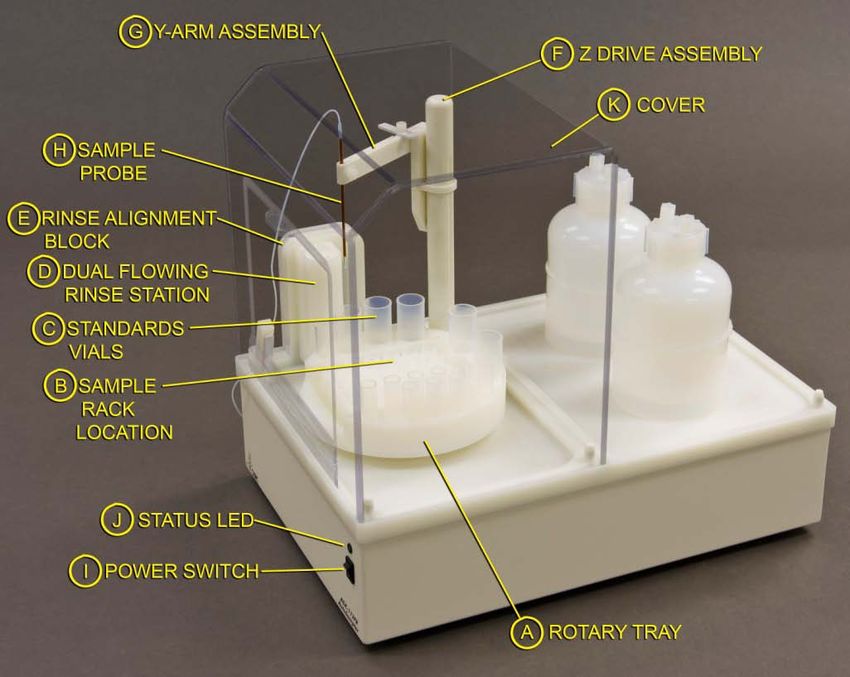
Assemble and Place the Sample Rack and Vials
Never attempt to load, unload or reposition the sample vial rack or sample
WARNING vials while the autosampler is operating. The sample probe may move
unexpectedly and cause an injury.
Figure 3-9. ASX-112FR Autosampler Rotary Tray
The ASX-112FR features a rotary tray, shown in Figure 3-9, which holds both
standards and samples. A variety of sample racks can be placed within the
center cavity of the rotary tray. Sample racks are classified as short or tall,
allowing the ASX-112FR to be configured in either a short or tall configuration.
Standards vials also vary between the short and tall configurations. For the
short configuration, standard positions 1 through 5 hold 20 mL vials and
standard positions 6 through 14 hold 4 mL vials. For the tall configuration,
standard positions 1 through 5 hold 30 mL vials and standard positions 6
through 14 hold 10 mL vials.
Short Rack Configuration
Figure 3-10. CETAC Sample Racks – Short Rack.
31ASX-112FR Autosampler Operator’s Manual
Chapter 3: Installing the Autosampler
Three CETAC sample racks are available for the short configuration. These are
shown in Figure 3-10.
To assemble and place the samples and standards for a short configuration,
complete the following steps:
1 Ensure the short sample tray adapter plate is screwed into place in the center
of the rotary tray. It should be placed so that the alignment guide is placed
nearest the guide dot as shown in Figure 3-9. An ASX-112FR ordered in a
short configuration will be shipped with the adapter plate in place.
2 Place the standards vials in the rotary tray as shown in Figure 3-9.
3 Load the sample vials in the sample tray and place the tray in the center of the
rotary tray aligning the groove on the bottom of the tray with the alignment
guide on the adapter plate. This should also align the two alignment dots on
the corner of the sample tray and the rotary tray.
A correctly placed sample vial rack will not move more than ± 0.2 millimeters
unless lifted. A tilted sample vial rack or vials indicate an improperly placed
rack or vials, which must be corrected before you operate the autosampler.
4 Replace the autosampler cover by sliding it into the groove in the rinse
alignment block.
The cover on the ASX-112FR has a hinged front door, secured by a bar latch,
which can be opened and closed during operation without impacting the
sampling sequence. The entire cover itself can also be fully removed during
operation without impact to the sampling sequence; however, this is not
recommended as the removal act could result in an impact to the Y-arm
assembly causing an alignment error. In the case of a mechanically induced
alignment error, the power to the unit would need to be cycled off and on to
realign the Y-arm.
Tall Rack Configuration
30 42
Figure 3-11. Bel-Art Sample Racks.
32ASX-112FR Autosamplers Operator’s Manual
Chapter 3: Installing the Autosampler
Two half Bel-Art racks are provided for the tall configuration. The tray layouts
are shown in Figure 3-11.
To assemble and place the samples and standards for a tall configuration,
complete the following steps:
1 Assemble the Bel-Art rack by snapping the middle and top sections to the
bottom according to the instructions included with the rack.
2 Ensure the short sample tray adapter plate is not screwed into place in the
center of the rotary tray. An ASX-112FR ordered in a tall configuration will be
shipped without the adapter plate in place.
3 Place the standards in the rotary tray as shown in Figure 3-9.
4 Load the sample vials in the sample tray and place the tray in the center of the
rotary tray.
A correctly placed sample rack will not move more than ±0.2 millimeters (mm)
unless lifted. A tilted sample vial rack or vials indicate an improperly placed
rack or vials, which must be corrected before you operate the autosampler.
5 Replace the autosampler cover by sliding it into the groove in the rinse
alignment block.
The cover on the ASX-112FR has a hinged door, secured by a bar latch, which
can be opened and closed during operation without impacting the sampling
sequence. The entire cover itself can also be fully removed during operation
without impact to the sampling sequence; however, this is not recommended
as the removal act could result in an impact to the Y-Arm assembly causing an
alignment error. In the case of a mechanically induced alignment error, the
power to the unit would need to be cycled off and on to realign the Y-arm.
33ASX-112FR Autosampler Operator’s Manual
Chapter 3: Installing the Autosampler
Connecting the Autosampler to the Power Supply
The autosampler is powered by the supplied external desktop "brick" power
supply. Ensure that you position the autosampler so that the location where
the power supply cord plugs into it is easily accessible (is not blocked) and it
can be quickly disconnected if needed. In case of hazard, the system should be
disconnected from the power source.
1 Turn the power switch on the autosampler OFF.
2 Check the plug on the power cord to verify that it is of the correct type for your
country.
3 Plug the power cord into a power outlet.
4 Plug the power cord into the power supply.
Power Cord to
Grounded AC Power
Outlet
To POWER
Connector on
Autosampler
Figure 3-12 Desktop "Brick" Power Supply
5 Plug the power supply into the 24V connector on back of the autosampler.
6 Turn the power switch on the front of the autosampler ON.
It is important to use the appropriate power cord for your country. See
“Power requirements” on page 76.
“Power Cord Set Requirements” on page 77.
FIRE AND SHOCK HAZARD
WARNING Use only the provided desktop power supply. The power supply must be
plugged into an outlet which has a protective ground connection.
34ASX-112FR Autosamplers Operator’s Manual
Chapter 3: Installing the Autosampler
Connecting the Autosampler to an Analytical
Instrument
You can connect the autosampler directly to a sample introduction peristaltic
pump and then to the ICP-MS or to a sample introduction device, such as the
CETAC Aridus II™ Desolvating Nebulizer System. To do so, complete the
following steps:
1 Determine the free length of the sample probe tubing you need, add 10
centimeters, and cut the free end of the sample probe to length.
Determining the free length includes allowance for movement of the Y-arm in
the X, Y, and Z axes. The additional 10 centimeters provides a service loop for
unrestricted sample probe motion.
Excessively shortened sample probe tubing is not repairable and must be
replaced.
2 Connect the free end of the sample transfer tubing to the inlet of the analytical
instrument’s peristaltic pump tubing.
The free end may be connected directly to the ICP-MS nebulizer. If the CETAC
C-Flow PFA nebulizer is used (the free end acting as the sample probe for the
ASX-112FR) then the nebulizer may be installed directly into the Aridus II™
PFA spray chamber or the host ICP-MS spray chamber.
Connect the ASX-112FR Autosampler to the Host
Computer
Instrument control software on the ICP-MS host computer controls both the
analytical instrument and the autosampler. You cannot operate the
autosampler until you establish a communications interface between the
autosampler and the host computer. It is through this interface that the host
computer directs the operation of the autosampler. The autosampler supports
the following communications protocols:
The serial (RS-232) protocol is the standard configuration. There are two
RS-232 serial ports on the autosampler, and a serial interface kit is shipped
with the autosampler.
The parallel (IEEE-488) protocol is less common than the serial
configuration. An IEEE-488 interface kit is available as an optional
accessory to the ASX-112FR.
The USB interface is an optional configuration. A virtual COM port is
created when using the USB and therefore, the connection looks like a
standard RS-232 serial port to the host PC software.
NOTE:
Although the autosampler supports several communications protocols, the
host computer governs which protocol is used. To determine which protocol is
35You can also read