Intel Desktop Board DQ67EP Product Guide
←
→
Page content transcription
If your browser does not render page correctly, please read the page content below
Intel® Desktop Board DQ67EP
Product Guide
Order Number: G15491-001
Revision History
  Revision        Revision History                                                            Date
  -001            First release of the Intel® Desktop Board DQ67EP Product Guide              December 2010

  Disclaimer
  INFORMATION IN THIS DOCUMENT IS PROVIDED IN CONNECTION WITH INTEL® PRODUCTS. NO LICENSE,
  EXPRESS OR IMPLIED, BY ESTOPPEL OR OTHERWISE, TO ANY INTELLECTUAL PROPERTY RIGHTS IS
  GRANTED BY THIS DOCUMENT. EXCEPT AS PROVIDED IN INTEL’S TERMS AND CONDITIONS OF SALE FOR
  SUCH PRODUCTS, INTEL ASSUMES NO LIABILITY WHATSOEVER, AND INTEL DISCLAIMS ANY EXPRESS OR
  IMPLIED WARRANTY, RELATING TO SALE AND/OR USE OF INTEL PRODUCTS INCLUDING LIABILITY OR
  WARRANTIES RELATING TO FITNESS FOR A PARTICULAR PURPOSE, MERCHANTABILITY, OR INFRINGEMENT
  OF ANY PATENT, COPYRIGHT OR OTHER INTELLECTUAL PROPERTY RIGHT. Intel products are not intended
  for use in medical, life saving, or life sustaining applications. Intel may make changes to specifications and
  product descriptions at any time, without notice.
  Intel Desktop Board DQ67EP may contain design defects or errors known as errata which may cause the
  product to deviate from published specifications. Current characterized errata are available on request.

  Contact your local Intel sales office or your distributor to obtain the latest specifications and before placing
  your product order.

  Copies of documents which have an ordering number and are referenced in this document, or other Intel
  literature, may be obtained from Intel Corporation by going to the World Wide Web site at:
  http://www.intel.com/ or by calling 1-800-548-4725.

  Intel, Intel Core, and Pentium are trademarks of Intel Corporation in the U.S. and other countries.
  * Other names and brands may be claimed as the property of others.

  Copyright © 2010, Intel Corporation. All rights reserved.
Preface
  This Product Guide gives information about board layout, component installation, BIOS
  update, and regulatory requirements for Intel® Desktop Board DQ67EP.

Intended Audience
  The Product Guide is intended for technically qualified personnel. It is not intended for
  general audiences.

Use Only for Intended Applications
  All Intel Desktop Boards are evaluated as Information Technology Equipment (I.T.E.)
  for use in personal computers (PC) for installation in homes, offices, schools, computer
  rooms, and similar locations. The suitability of this product for other PC or embedded
  non-PC applications or other environments, such as medical, industrial, alarm systems,
  test equipment, etc. may not be supported without further evaluation by Intel.

Document Organization
  The chapters in this Product Guide are arranged as follows:
  1   Desktop Board Features: a summary of product features
  2   Installing and Replacing Desktop Board Components: instructions on how to install
      the Desktop Board and other hardware components
  3   Updating the BIOS: instructions on how to update the BIOS
  A   Error Messages and Indicators: information about BIOS error messages and beep
      codes
  B   Regulatory Compliance: describes the board’s adherence to safety standards and
      EMC regulations and its product certifications

Conventions
  The following conventions are used in this manual:

  CAUTION
  Cautions warn the user about how to prevent damage to hardware or loss of data.

  NOTE
  Notes call attention to important information.

                                                                                         iii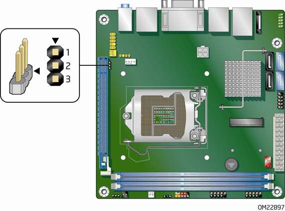
Intel Desktop Board DQ67EP Product Guide

Terminology
     The table below gives descriptions of some common terms used in the product guide.
     Term          Description
     GB            Gigabyte (1,073,741,824 bytes)
     GHz           Gigahertz (one billion hertz)
     KB            Kilobyte (1024 bytes)
     MB            Megabyte (1,048,576 bytes)
     Mb            Megabit (1,048,576 bits)
     MHz           Megahertz (one million hertz)

iv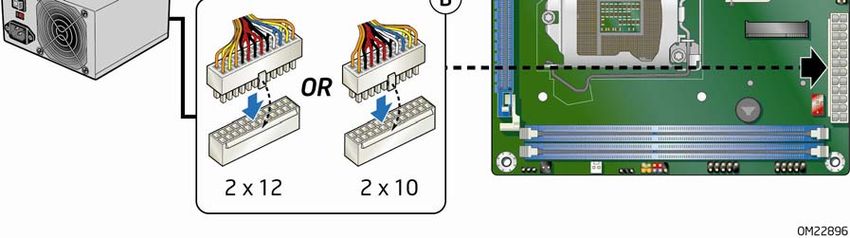
Contents
1 Desktop Board Features
  Supported Operating Systems..............................................................................11
  Desktop Board Components.................................................................................12
  Processor..........................................................................................................14
  Intel® Q67 Express Chipset .................................................................................15
  Main Memory.....................................................................................................15
  Graphics Subsystem ...........................................................................................16
        Integrated Graphics ....................................................................................16
              DisplayPort* .......................................................................................16
              Digital Visual Interface .........................................................................16
        PCI Express* x16 Graphics ..........................................................................17
  Audio Subsystem ...............................................................................................17
  LAN Subsystem .................................................................................................18
  USB Support .....................................................................................................19
  SATA Support....................................................................................................19
        SATA RAID ................................................................................................20
        Intel® Rapid Recover Technology ..................................................................20
  Expandability.....................................................................................................20
  Legacy I/O ........................................................................................................21
  BIOS ................................................................................................................21
        SATA Auto Configuration .............................................................................21
        PCI*/PCI Express Auto Configuration.............................................................21
        BIOS Security Passwords .............................................................................21
        Hard Disk Drive Passwords...........................................................................22
  Platform Management and Protection ....................................................................24
        Intel® vPro™ Technology .............................................................................24
              Intel® Active Management Technology ...................................................24
              Intel® Virtualization Technology.............................................................27
              Intel® Trusted Execution Technology ......................................................27
              Intel® Fast Call for Help........................................................................27
              Trusted Platform Module (TPM) .............................................................27
        Fan Speed Control and Hardware Monitoring ..................................................28
        Power Management ....................................................................................28
              Software Support ................................................................................28
              Hardware Support ...............................................................................28
  Onboard Speaker ...............................................................................................31
  Real-Time Clock Subsystem.................................................................................31

2 Installing and Replacing Desktop Board Components
  Before You Begin ...............................................................................................33
  Installation Precautions.......................................................................................34
        Prevent Power Supply Overload ....................................................................34
        Observe Safety and Regulatory Requirements.................................................34
  Installing the I/O Shield ......................................................................................35
  Installing and Removing the Desktop Board ...........................................................36

                                                                                                                       v
Intel Desktop Board DQ67EP Product Guide
Installing and Removing a Processor .....................................................................37
Installing a Processor ..................................................................................37
Installing a Processor Fan Heat Sink ..............................................................41
Connecting the Processor Fan Heat Sink Cable................................................41
Removing the Processor ..............................................................................41
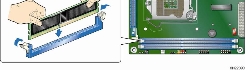
Installing and Removing System Memory ..............................................................42
Installing DIMMs ........................................................................................43
Removing DIMMs........................................................................................45
Installing and Removing PCI Express x16 Graphics Cards.........................................45
Installing a PCI Express x16 Graphics Card ....................................................45
Removing a PCI Express x16 Graphics Card....................................................47
Installing a Wireless LAN Card in the PCI Express Half-Mini Card Slot (Optional)..........48
Connecting Serial ATA (SATA) Cables....................................................................49
Connecting to the Internal Headers ......................................................................50
Front Panel Audio Header ............................................................................51
Serial Header .............................................................................................51
Front Panel USB 2.0 Headers........................................................................52
Front Panel Header .....................................................................................52
Alternate Front Panel Power LED Header ........................................................53
Intel FCFH Header ......................................................................................53
Chassis Intrusion Header .............................................................................53
S/PDIF Header ...........................................................................................54
Internal Mono Speaker Header .....................................................................54
Connecting to the Audio System...........................................................................55
Connecting System Fan and Power Supply Cables ...................................................56
Connecting a System Fan Cable ....................................................................56
Connecting Power Supply Cables ..................................................................57
Setting the BIOS Configuration Jumper .................................................................58
Clearing Passwords in the BIOS Setup Program ......................................................59
Replacing the Battery .........................................................................................60
3 Updating the BIOS
Updating the BIOS with the Intel® Express BIOS Update Utility.................................67
Updating the BIOS Using the F7 Function Key ........................................................68
Updating the BIOS with the ISO Image BIOS Update File or the Intel® Flash
Memory Update Utility...................................................................................69
Obtaining the BIOS Update File ....................................................................69
Updating the BIOS with the Intel Flash Memory Update Utility...........................69
Updating the BIOS with the ISO Image BIOS Update File .................................70
Recovering the BIOS ...................................................................................71
A Error Messages and Indicators
BIOS Error Codes...............................................................................................73
BIOS Error Messages ..........................................................................................74
B Regulatory Compliance
Safety Standards ...............................................................................................75
Battery Caution ..........................................................................................75
European Union Declaration of Conformity Statement..............................................76
Product Ecology Statements ................................................................................77
Recycling Considerations .............................................................................77
China RoHS ...............................................................................................80
vi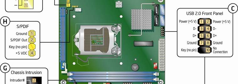
Contents
EMC Regulations ................................................................................................81
FCC Declaration of Conformity ......................................................................81
Canadian Department of Communications Compliance Statement ......................82
Japan VCCI Statement ................................................................................82
Korea Class B Statement .............................................................................83
Ensure Electromagnetic Compatibility (EMC) Compliance ..................................83
Product Certifications..........................................................................................84
Board-Level Certifications ............................................................................84
Chassis- and Component-Level Certifications ..................................................85
ENERGY STAR*, e-Standby, and ErP Compliance ....................................................85
Figures
1. Intel Desktop Board DQ67EP Components........................................................12
2. LAN Status LEDs ..........................................................................................18
3. Location of the Intel MEBX Reset Header..........................................................26
4. Location of the Standby Power Indicator ..........................................................30
5. Installing the I/O Shield ................................................................................35
6. Intel Desktop Board DQ67EP Mounting Screw Hole Locations ..............................36
7. Unlatch the Socket Lever ...............................................................................37
8. Lift the Load Plate.........................................................................................38
9. Remove the Processor from the Protective Cover ..............................................39
10. Install the Processor .....................................................................................39
11. Secure the Load Plate in Place ........................................................................40
12. Connecting the Processor Fan Heat Sink Power Cable to the Processor
Fan Header..................................................................................................41
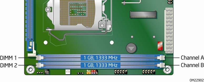
13. Dual Channel Memory Configuration Example ...................................................42
14. Use DDR3 DIMMs .........................................................................................43
15. Installing a DIMM .........................................................................................44
16. Installing a PCI Express x16 Graphics Card ......................................................46
17. Removing a PCI Express x16 Graphics Card......................................................47
18. Installing a Wireless LAN Card ........................................................................48
19. Connecting a Serial ATA Cable........................................................................49
20. Internal Headers ..........................................................................................50
21. Back Panel Audio Connectors .........................................................................55
22. Location of the System Fan Header .................................................................56
23. Connecting Power Supply Cables ....................................................................57
24. Location of the BIOS Configuration Jumper Block ..............................................58
25. Removing the Battery ...................................................................................65
26. Intel Desktop Board DQ67EP China RoHS Material Self Declaration Table..............80
vii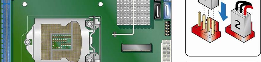
Intel Desktop Board DQ67EP Product Guide

Tables
       1.    Feature Summary.......................................................................................... 9
       2.    Intel Desktop Board DQ67EP Components........................................................13
       3.    LAN Status LEDs States .................................................................................18
       4.    Master Key and User Hard Disk Drive Password Functions ..................................22
       5.    Front Panel Audio Signal Names for Intel HD Audio............................................51
       6.    Front Panel Audio Header Signal Names for AC ’97 Audio ...................................51
       7.    Serial Port Header ........................................................................................51
       8.    Front Panel USB 2.0 Headers Signal Names ......................................................52
       9.    Front Panel Header Signal Names ...................................................................52
       10.   Alternate Front Panel Power LED Header Signal Names ......................................53
       11.   Intel FCFH Header Signal Names ....................................................................53
       12.   Chassis Intrusion Header Signal Names ...........................................................53
       13.   S/PDIF Header Signal Names .........................................................................54
       14.   Internal Mono Speaker Header .......................................................................54
       15.   Jumper Settings for the BIOS Setup Program Modes..........................................59
       16.   BIOS Beep Codes .........................................................................................73
       17.   Front-panel Power LED Blink Codes .................................................................74
       18.   BIOS Error Messages ....................................................................................74
       19.   Safety Standards..........................................................................................75
       20.   EMC Regulations...........................................................................................81
       21.   Regulatory Compliance Marks.........................................................................84

viii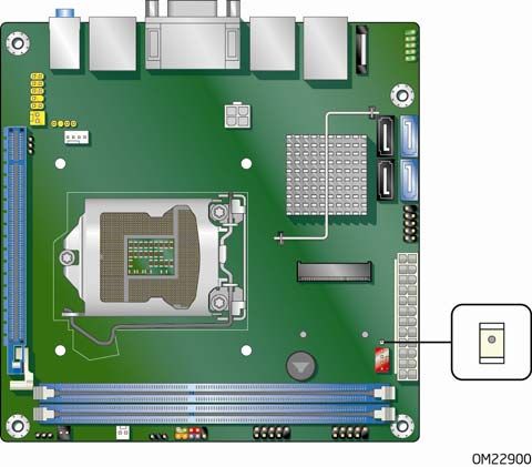
1 Desktop Board Features
  This chapter briefly describes the features of Intel® Desktop Board DQ67EP. Table 1
  summarizes the major features of the Desktop Board.

  Table 1. Feature Summary
  Form Factor           Mini-ITX (170.18 millimeters [6.7 inches] x 170.18 millimeters
                        [6.7 inches])
                        • Intel® Core™ i7, Intel® Core™ i5, Intel® Core™ i3, and
  Processor Support
                          Intel® Pentium processors in an LGA1155 package:
                          ―   Integrated graphics processing (processors with Intel® Graphics
                              Technology)
                          ― External graphics interface controller
                          ― Integrated memory controller

                        Note: Use of a 95 W TDP processor requires a custom thermal
                        solution. See the Note on page 14 for more information.
  Chipset               Intel® Q67 Express Chipset consisting of the Intel® Q67 Express
                        Platform Controller Hub (PCH)
  Memory Support        • Two 240-pin DDR3 SDRAM Dual Inline Memory Module (DIMM)
                          sockets
                        • Support for DDR3 1333 MHz and DDR3 1066 MHz DIMMs
                        • Support for 1 Gb, 2 Gb, and 4 Gb memory technology
                        • Support for up to 16 GB of system memory with two DIMMs using
                          4 Gb memory technology
                        • Support for non-ECC memory
  Graphics Support      • Integrated graphics support for processors with Intel Graphics
                          Technology:
                          ―   DVI-I
                          ―   DVI-D
                          ―   DisplayPort* interface
                        • Discrete graphics support for PCI Express* 2.0 x16 add-in graphics
                          cards
  Audio                 Intel® High Definition Audio:
                        • Realtek* ALC888S audio codec
                        • DisplayPort* digital audio support
                        • S/PDIF audio header
                        • Front panel audio header
                        • Mono speaker header
  Expansion             • One PCI Express 2.0 x16 add-in card connector
  Capabilities          • One PCI Express Mini Card add-in connector (Half-Mini Card Slot)
                                                                                      continued

                                                                                               9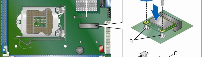
Intel Desktop Board DQ67EP Product Guide

     Table 1. Feature Summary (continued)
     Peripheral            • Twelve USB ports:
     Interfaces              ― Two USB 3.0 ports are implemented with stacked back panel
                                 connectors (blue)
                             ― Four USB 2.0 ports are implemented with stacked back panel
                                 connectors (black)
                             ― Six USB 2.0 front panel ports are implemented with three
                                 dual-port internal headers
                           • Six SATA interfaces through the Intel Q67 Express Chipset with
                             Intel® Rapid Storage Technology RAID support:
                             ― Two internal SATA 6 Gb/s ports (blue)
                             ― Two internal SATA 3 Gb/s ports (black)
                             ― Two backpanel eSATA 3 Gb/s ports (red)
                           • One serial port header
     LAN Support           Intel® 82579LM Gigabit (10/100/1000 Mb/s) Ethernet LAN controller
                           with support for:
                           • Intel® Active Management Technology (Intel® AMT) 7.0
                           • ASF 2.0
     Legacy I/O            • Nuvoton* W83677HG-i I/O controller for hardware management
                             and serial port support
     BIOS                  • Intel® BIOS resident in an SPI Flash device
                           • Support for Advanced Configuration and Power Interface (ACPI),
                             Plug and Play, and SMBIOS
     Instantly Available   • Support for PCI Local Bus Specification, Revision 2.2
     PC Technology         • Support for PCI Express Base Specification, Revision 2.0
                           • Suspend to RAM support
                           • Wake on PCI Express, LAN, front panel, serial, and USB ports
     Hardware              • Hardware monitoring through the Nuvoton I/O controller
     Monitoring            • Voltage sense to detect out of range power supply voltages
                           • Thermal sense to detect out of range thermal values
                           • Two fan headers using PWM control
                           • 4-pin headers for processor and system fans
                           • 4-wire and 3-wire (linear) fan speed control support for the system
                             fan
                           • Support for Platform Environmental Control Interface (PECI)
          ®
     Intel vPro™           • Intel® Active Management Technology (Intel® AMT) 7.0
     Technology            • Intel® Trusted Execution Technology (Intel® TXT)
                           • Intel® Fast Call for Help (Intel® FCFH)
                           • Intel® Virtualization Technology (Intel® VT)
                           • Intel® Virtualization for Directed I/O (Intel® VT-d)
                           • Hardware-based Keyboard-Video-Mouse (KVM) Remote Control

10
Desktop Board Features
Supported Operating Systems
The Desktop Board supports the following operating systems:
• Microsoft Windows* 7 Ultimate 64-bit edition
• Microsoft Windows 7 Ultimate 32-bit edition
• Microsoft Windows 7 Professional 64-bit edition
• Microsoft Windows 7 Professional 32-bit edition
• Microsoft Windows 7 Home Premium 64-bit edition
• Microsoft Windows 7 Home Premium 32-bit edition
• Microsoft Windows 7 Starter 64-bit edition
• Microsoft Windows 7 Starter 32-bit edition
• Microsoft Windows Vista* Ultimate 32-bit edition
• Microsoft Windows Vista Business 32-bit edition
• Microsoft Windows Vista Home Premium 32-bit edition
• Microsoft Windows Vista Home Basic 32-bit edition
• Microsoft Windows Vista Ultimate 64-bit edition
• Microsoft Windows Vista Business 64-bit edition
• Microsoft Windows Vista Home Premium 64-bit edition
• Microsoft Windows Vista Home Basic 64-bit edition
• Microsoft Windows* XP Media Center Edition 2005
• Microsoft Windows XP Professional
• Microsoft Windows XP Professional x64 Edition
• Microsoft Windows XP Home
11Intel Desktop Board DQ67EP Product Guide
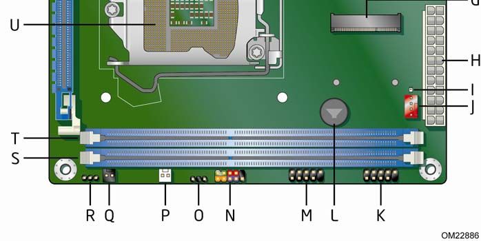
Desktop Board Components
Figure 1 shows the approximate location of the major components on Intel Desktop
Board DQ67EP.
Figure 1. Intel Desktop Board DQ67EP Components
12Desktop Board Features
Table 2. Intel Desktop Board DQ67EP Components
Label Description
A Back panel connectors
B Battery
C Serial port header
D 12 V processor core voltage connector (2 x 2 pin)
E SATA connectors
F Front panel USB 2.0 header
G PCI Express Mini Card connector
H Main power connector (2 x 12 pin)
I Standby power indicator LED
J System fan header
K Front panel USB 2.0 header
L Speaker
M Front panel USB 2.0 header
N Front panel header
O Alternate front panel power LED header
P Intel® Fast Call for Help (Intel® FCFH) header
Q Chassis intrusion header
R BIOS configuration jumper block
S DDR3 DIMM 2 socket
T DDR3 DIMM 1 socket
U Processor socket
V PCI Express 2.0 x16 add-in card connector
W Processor fan header
X Intel® Management Engine BIOS Extension (Intel® MEBX) reset header
Y S/PDIF header
Z Internal mono speaker header
AA Front panel audio header
13Intel Desktop Board DQ67EP Product Guide
Online Support
For more information on Intel Desktop Board DQ67EP consult the following online
resources:
• Intel Desktop Board DQ67EP http://www.intel.com/products/motherboard/index.ht
m
• Desktop Board Support http://www.intel.com/p/en_US/support?iid=hdr+supp
ort
• Available configurations for Intel http://ark.intel.com
Desktop Board DQ67EP
• Supported processors http://processormatch.intel.com
• Chipset information http://www.intel.com/products/desktop/chipsets/inde
x.htm
• BIOS and driver updates http://downloadcenter.intel.com/
• Integration information http://www.intel.com/support/go/buildit
Processor
CAUTION
Failure to use an appropriate power supply and/or not connecting the 12 V (2 x 2 pin)
power connector to the Desktop Board may result in damage to the board, or the
system may not function properly.
Intel Desktop Board DQ67EP supports the Intel Core i7, Intel Core i5, Intel Core i3,
and Intel Pentium processors in the LGA1155 package. Processors are not included
with the Desktop Board and must be purchased separately. The processor connects to
the Desktop Board through an LGA1155 socket.
NOTE
Use of a 95 W TDP processor requires a custom thermal solution. Pairing a miniITX
chassis and a 95 W TDP processor with the supplied standard Intel thermal solution
may not meet thermal requirements. Verify that your thermal solution and chassis will
meet the necessary thermal requirements. Failing to do so will cause the processor to
throttle, significantly decreasing system performance.
For information on supported processors for Intel Desktop Board DQ67EP, go to
http://processormatch.intel.com.
14Desktop Board Features
Intel® Q67 Express Chipset
The Intel Q67 Express Chipset, consisting of the Intel Q67 Platform Controller Hub
(PCH), provides interfaces to the processor and the USB, SATA, LPC, audio, network,
display, and PCI Express interfaces. The PCH is a centralized controller for the board’s
I/O paths.
Main Memory
NOTE
To be fully compliant with all applicable Intel ® SDRAM memory specifications, the
board should be populated with DIMMs that support the Serial Presence Detect (SPD)
data structure. If your memory modules do not support SPD, you will see a
notification to this effect on the screen at power up. The BIOS will attempt to
configure the memory controller for normal operation.
The board has two DIMM sockets and supports the following memory features:
• Two independent memory channels with interleaved mode support
• Support for non-ECC, unbuffered, single-sided or double-sided DIMMs with x8
organization
• 16 GB maximum total system memory (with 4 Gb memory technology)
• Minimum total system memory: 1 GB using 1 Gb x8 modules
• Serial Presence Detect
• DDR3 1333 MHz and DDR3 1066 MHz SDRAM DIMMs
NOTE
32-bit operating systems are limited to a maximum of 4 GB of memory. These
operating systems will report less than 4 GB because of the memory used by add-in
graphics cards and other system resources.
15Intel Desktop Board DQ67EP Product Guide
Graphics Subsystem
The board supports either integrated graphics (Intel Graphics Technology) or PCI
Express 2.0 x16 graphics.
Integrated Graphics
The board supports integrated graphics through the Intel® Flexible Display Interface
(Intel® FDI) for processors with Intel Graphics Technology. When using a processor
with integrated graphics, the board will support only two of the three integrated
graphics interfaces simultaneously: DisplayPort, DVI-I, DVI-D.
NOTE
The board will support up to two integrated graphics interfaces plus one PCI Express
Graphics card simultaneously with required changes to the BIOS setup.
DisplayPort*
DisplayPort is a digital communication interface that utilizes differential signaling to
achieve a high bandwidth bus interface designed to support connections between PCs
and monitors, projectors, and TV displays. DisplayPort is suitable for display
connections between consumer electronics devices such as high definition optical disc
players, set top boxes, and TV displays. DisplayPort output can be converted to High-
Definition Multimedia Interface* (HDMI*) output using a DisplayPort-HDMI converter.
DisplayPort’s maximum supported display resolution is 2560 x 1600 at a 60 Hz refresh
rate with a 16:10 aspect ratio (WQXGA). DisplayPort 1.1 adds support for High
Bandwidth Digital Content Protection (HDCP) version 1.3 which enables viewing of
protected content from Blu-ray Disc* and HD-DVD optical media over DisplayPort 1.1
connections.
For more information about DisplayPort technology go to http://www.displayport.org.
Digital Visual Interface
Intel Desktop Board DQ67EP supports Digital Visual Interface (DVI) displays with two
back panel ports: a DVI-D port and a DVI-I port.
The DVI-I port supports both digital and analog DVI displays. The maximum
supported resolution is 2048 x 1536 at a 75 Hz refresh rate (QXGA). The DVI-I port is
compliant with the DVI 1.0 specification. DVI analog output from the DVI-I port can
be converted to VGA for viewing on a VGA display using a DVI-VGA converter.
The DVI-D port supports only digital DVI displays. The maximum supported resolution
is 2048 x 1536 at a 75 Hz refresh rate (QXGA). The DVI-D port is compliant with the
DVI 1.0 specification.
16Desktop Board Features
PCI Express* x16 Graphics
The Intel Core i7, Intel Core i5, Intel Core i3, and Intel Pentium processors in an
LGA1155 socket support discrete add-in graphics cards via the PCI Express 2.0 x16
add-in card connector. The board supports the following PCI Express speeds:
• PCI Express 2 frequency of 2.5 GHz which results in 5.0 Gb/s in each direction
(500 MB/s) per lane. The maximum theoretical bandwidth on the interface is
8 GB/s in each direction, simultaneously, when operating in x16 mode.
• PCI Express 1 frequency of 1.25 GHz resulting in 2.5 Gb/s each direction
(250 MB/s) per lane. The maximum theoretical bandwidth on the interface is
4 GB/s in each direction, simultaneously, when operating in x16 mode.
Audio Subsystem
The board supports Intel High Definition Audio through a Realtek ALC888S audio codec
as well as through the DisplayPort interface.
The Realtek ALC888S-based audio subsystem provides the following features:
• 8-channel audio with independent multi-streaming stereo
• Advanced jack sense for the back panel audio connectors that enables the audio
codec to recognize the device that is connected to an audio port. The back panel
audio connectors are capable of retasking according to the user’s definition, or can
be automatically switched depending on the recognized device type.
• Stereo input and output via back panel connectors
• Headphone and Mic in functions for front panel audio connectors
• A signal-to-noise (S/N) ratio of 90 dB
The board provides onboard audio headers and back panel connectors.
The onboard audio headers include the following:
• Front panel audio (a 2 x 5 pin header that provides headphone and mic in signals
for front panel audio connectors)
• S/PDIF audio header (1 x 4 pin header)
• Internal mono speaker header (1 x 2 pin header)
Front panel headphone output is supported by a separate audio channel pair, allowing
multi-streaming audio configurations such as simultaneous 6-channel (5.1) surround
sound playback and stereo audio conferencing (through speakers connected to the
back panel audio connectors and a headset connected to front panel audio
connectors).
The onboard internal mono speaker header allows connection to an internal, low-
power speaker for basic system sound capability. The subsystem is capable of driving
a speaker load of 8 Ω at 1 W (rms) or 4 Ω at 1.5 W (rms).
The onboard S/PDIF header allows connection to coaxial or optical adapters for digital
audio output.
The back panel audio connectors are configurable through the audio device drivers.
Audio software and drivers are available from http://downloadcenter.intel.com/.
17Intel Desktop Board DQ67EP Product Guide
LAN Subsystem
The LAN subsystem includes:
• Intel 82579LM Gigabit (10/100/1000 Mb/s) Ethernet LAN controller with support
for:
⎯ Intel AMT 7.0
⎯ ASF 2.0
• RJ-45 LAN connector with integrated status LEDs
LAN software and drivers are available at http://downloadcenter.intel.com/.
Two LEDs are built into the RJ-45 LAN connector located on the back panel (see
Figure 2). These LEDs indicate the status of the LAN as shown in Table 3.
Figure 2. LAN Status LEDs
Table 3. LAN Status LEDs States
LED LED Color LED State Indicates
A (Link/Activity) Green Off LAN link is not established
On LAN link is established
Blinking LAN activity is occurring
B (Link Speed) N/A Off 10 Mb/s data rate
Green On 100 Mb/s data rate
Yellow On 1000 Mb/s data rate
18Desktop Board Features
USB Support
The Desktop Board supports USB 3.0 and USB 2.0. USB 3.0 is supported via two
USB 3.0 ports (blue) on the back panel. USB 3.0 ports are backward compatible with
USB 2.0 and USB 1.1 devices. The USB 3.0 ports are SuperSpeed, high-speed, full-
speed, and low-speed capable. USB 3.0 support requires both an operating system
and drivers that fully support USB 3.0 transfer rates.
There are 10 USB 2.0 ports (four ports routed to back panel connectors (black) and six
ports routed to three onboard headers). The USB 2.0 ports are high-speed, full-speed,
and low-speed capable. USB 2.0 support requires both an operating system and
drivers that fully support USB 2.0 transfer rates.
NOTE
Intel recommends connecting USB keyboard and mouse devices to USB 2.0 ports
(black). Operating system installation may be interrupted if keyboard and mouse
devices are connected to the SuperSpeed USB 3.0 ports (blue) due to the lack of
native USB 3.0 driver support from the operating system. The device driver for the
USB 3.0 host controller must be installed from the included Intel® Express Installer
Driver and Software DVD before it can be operational in the operating system.
SATA Support
The board provides six SATA channels, through the PCH, which support one device per
channel:
• Two internal SATA 6.0 Gb/s connectors (blue)
• Two internal SATA 3.0 Gb/s connectors (black)
• Two external SATA (eSATA) 3.0 Gb/s connectors (red) on the back panel for
external connections
19Intel Desktop Board DQ67EP Product Guide
SATA RAID
The Intel Q67 PCH supports Intel® Rapid Storage Technology (Intel® RST) which
enables the following RAID (Redundant Array of Independent Drives) levels:
• RAID 0 - data striping
• RAID 1 - data mirroring
• RAID 0+1 (or RAID 10) - data striping and mirroring
• RAID 5 - distributed parity
NOTE
In order to use supported RAID features, you must first enable RAID in the BIOS. Also,
during Microsoft Windows XP installation, you must press F6 to install the RAID
drivers. See your Microsoft Windows XP documentation for more information about
installing drivers during installation. Both Microsoft Windows Vista and Microsoft
Windows 7 include the necessary RAID drivers for both AHCI and RAID without the
need to install separate RAID drivers using the F6 switch in the operating system
installation process.
Intel® Rapid Recover Technology
The board incorporates Intel® Rapid Recover Technology (Intel® RRT). Intel RRT is a
feature of Intel RST. Intel RRT uses RAID 1 (mirroring) functionality to copy data from
a designated master drive to a designated recovery drive. The master drive data can
be copied to the recovery drive either continuously or on request.
When using the continuous update policy, changes made to the data on the master
drive while the recovery drive is disconnected or offline are automatically copied to the
recovery drive when it is reconnected. When using the on request update policy, the
master drive data can be restored to a previous state by copying the data on the
recovery drive back to the master drive.
Expandability
Intel Desktop Board DQ67EP provides the following expansion capability:
• One PCI Express 2.0 x16 interface
• One PCI Express Mini Card interface
20Desktop Board Features
Legacy I/O
The board’s Legacy I/O Controller provides the following legacy features:
• One serial port header
• Serial IRQ interface compatible with serialized IRQ support for Conventional PCI
bus systems
• Intelligent power management, including a programmable wake-up event interface
• Conventional PCI bus power management support
The BIOS Setup program provides configuration options for the Legacy I/O controller.
BIOS
The BIOS provides the Power-On Self-Test (POST), the BIOS Setup program, and the
PCI/PCI Express and SATA auto-configuration utilities. The BIOS is stored in the Serial
Peripheral Interface (SPI) Flash memory device.
The BIOS can be updated by following the instructions in Chapter 3 starting on
page 67.
SATA Auto Configuration
If you install a SATA device (such as a hard disk drive) in your computer, the auto-
configuration utility in the BIOS automatically detects and configures the device for
your computer. You do not need to run the BIOS Setup program after installing a
SATA device. You can override the auto-configuration options by specifying manual
configuration in the BIOS Setup program.
PCI*/PCI Express Auto Configuration
If you install a Conventional PCI or PCI Express add-in card in your computer, the
PCI/PCI Express auto-configuration utility in the BIOS automatically detects and
configures the resources (IRQs, DMA channels, and I/O space) for that add-in card.
You do not need to run the BIOS Setup program after you install a Conventional PCI or
PCI Express add-in card.
BIOS Security Passwords
The BIOS includes security features that restrict whether the BIOS Setup program can
be accessed and who can boot the computer. A supervisor password and a user
password can be set for the BIOS Setup and for booting the computer, with the
following restrictions:
• The supervisor password gives unrestricted access to view and change all Setup
options. If only the supervisor password is set, pressing at the password
prompt of Setup gives the user restricted access to Setup.
21Intel Desktop Board DQ67EP Product Guide
• If both the supervisor and user passwords are set, you must enter either the
supervisor password or the user password to access Setup. Setup options are then
available for viewing and changing depending on whether the supervisor or user
password was entered.
• Setting a user password restricts who can boot the computer. The password
prompt is displayed before the computer is booted. If only the supervisor
password is set, the computer boots without asking for a password. If both
passwords are set, you can enter either password to boot the computer.
For instructions on resetting the password, go to Clearing Passwords on page 59.
Hard Disk Drive Passwords
NOTE
On this board, the Hard Disk Drive Password Security feature is only supported on
SATA port 0. Since the passwords are stored on the hard disk drive, if the drive is
relocated to another SATA port or computer that does not support the Hard Disk Drive
Password Security feature, the drive will not be accessible.
The board’s Hard Disk Drive Password Security feature blocks read and write accesses
to the hard disk drive until the correct password is entered. Hard disk drive passwords
are set in BIOS Setup and are prompted for during the POST. For convenient support
of ACPI S3 resume, the system BIOS automatically unlocks drives on resume from S3.
The User hard disk drive password, when set, will be required upon each power cycle
until the Master Key or User hard disk drive password is entered.
The Master Key hard disk drive password, when set, will not lock the hard disk drive.
The Master Key hard disk drive password is an unlock override that can be used in the
event that the User hard disk drive password has been forgotten. Only the installation
of the User hard disk drive password will cause a hard disk drive to be locked upon a
system power cycle.
Table 4 shows the effects of setting the hard disk drive passwords.
Table 4. Master Key and User Hard Disk Drive Password Functions
Password Set Password During Boot
Neither None
Master only None
User only User only
Master and User Master or User
22Desktop Board Features
During every POST, if a User hard disk drive password is set, POST execution will
pause with the following prompt to force the user to enter the Master Key or User hard
disk drive password:
Enter Hard Disk Drive Password:
Upon successful entry of the Master Key or User hard disk drive password, the system
will continue with the normal POST.
If the hard disk drive password is not correctly entered, the system will go back to the
above prompt. The user will have three attempts to correctly enter the hard disk drive
password. After the third unsuccessful hard disk drive password attempt, the system
will halt with the message:
Hard Disk Drive Password Entry Error
A manual power cycle will be required to resume system operation.
NOTE
The Hard Disk Drive Password Security feature is not supported in PCH RAID mode.
Secured hard disk drives attached to the system when the system is in PCH RAID
mode will not be accessible due to the disabling of BIOS Hard Disk Drive Password
support.
23Intel Desktop Board DQ67EP Product Guide
Platform Management and Protection
Intel Desktop Board DQ67EP integrates several functions designed to manage the
system and lower the total cost of ownership (TCO) of the system. These system
management functions are designed to report errors, diagnose the system, and
recover from system lockups without the aid of an external microcontroller. The board
also includes several fan speed control and power management features.
Intel® vPro™ Technology
Intel vPro Technology is a set of processor and platform capabilities designed to enable
greater proactive security, enhanced maintenance, and improved remote management
both inside and outside the corporate firewall. These include:
• Intel Active Management Technology (Intel AMT)
• Intel Virtualization Technology (Intel VT)
• Intel Trusted Execution Technology (Intel TXT)
• Intel Virtualization Technology for Directed I/O (Intel VT-d)
• Intel Fast Call for Help (Intel FCFH)
• Trusted Platform Module (TPM)
Intel® Active Management Technology
Intel AMT offers IT organizations tamper-resistant and persistent management
capabilities. Specifically, Intel AMT is a hardware-based solution that uses out of band
communication to manage access to client systems in addition to offering encrypted
and persistent asset management and remote diagnostics and/or recovery capabilities
for networked platforms. With Intel AMT, IT organizations can easily get accurate
platform information, and can perform remote updating, diagnostics, debugging, and
repair of a system, regardless of the state of the operating system or the power state
of the system.
The Intel AMT subsystem consists of:
• Intel Management Engine (Intel ME) microcontroller embedded in the Intel Q67
PCH
• Intel 82579LM Gigabit (10/100/1000 Mb/s) Ethernet LAN controller
• BIOS/SPI Flash (64 Mb)
• Intel MEBX reset header
• Intel® Centrino® Advanced-N 6200 Wireless Adapter (optional). For instructions
for installing this PCI Express Half-Mini Card, see page 48.
NOTE
Software with Intel AMT capability is required to take advantage of Intel AMT platform
management capabilities.
24Desktop Board Features
The key features of Intel AMT include:
• Secure Out of Band (OOB) system management that allows remote management
of PCs regardless of system power or operating system state.
• Remote troubleshooting and recovery that can significantly reduce desk-side visits
and potentially increasing efficiency of IT technical staff.
• Proactive alerting that decreases downtime and minimizes time to repair.
• Third party non-volatile storage that prevents users from removing critical
inventory, remote control, or virus protection agents.
• Remote hardware and software asset tracking that eliminates time-consuming
manual inventory tracking, which also reduces asset accounting costs.
• System Defense 2
• Remote Configuration (RCFG)
⎯ Client Control Mode Setup and Configuration
• KVM (Keyboard-Video-Mouse) Remote Control. KVM Remote Control requires the
use of an Intel processor with integrated graphics. The maximum resolution
supported by KVM Remote Control is 1920 x 1200.
• PC Alarm Clock
For more information about Intel AMT, go to
http://www.intel.com/technology/platform-technology/intel-amt/index.htm.
Intel AMT Software and Drivers
Intel AMT software and drivers are available from Intel’s World Wide Web site. The
package usually consists of the following components:
• Intel® Management Engine Interface (Intel® MEI)
• Serial Over LAN (SOL) driver
• Local Manageability Service (LMS)
• User Notification Service (UNS)
• Intel® ME WMI provider
• Intel® Active Management Technology NAC Posture Plug-in
• Intel Control Center
• Intel® Management and Security Status Application
25Intel Desktop Board DQ67EP Product Guide
Intel® MEBX Reset Header
This header (see Figure 3) allows you to reset the Intel AMT configuration to the
factory defaults. Momentarily shorting pins 1 and 2 with a jumper (not supplied) will
accomplish the following:
• Return all Intel ME parameters to their default values.
• Delete any user entered information, including PID/PPS and user entered Hash
Certificates. USB key and remote configuration data will be removed if the
parameters are not default parameters.
• Reset the Intel MEBX password to the default value (admin).
Figure 3. Location of the Intel MEBX Reset Header
26Desktop Board Features
Intel® Virtualization Technology
Intel VT is a processor technology that enables a platform to run multiple operating
systems and applications as independent machines, allowing one computer system to
function as multiple "virtual" systems. It also provides the “assisted hardware
virtualization” required by some operating systems for backward compatibility, such as
Windows XP Mode for Microsoft Windows 7.
NOTE
Intel VT requires an Intel processor that supports Intel VT.
Intel® Trusted Execution Technology
Intel TXT helps protect the platform against software-based attacks and preserves the
confidentiality and integrity of the data created and stored on the system. It
accomplishes this by using a measured launch and leveraging Intel VT to produce a
protected environment for the execution of sensitive applications.
NOTE
Intel TXT requires an Intel processor that supports Intel TXT.
Intel® Fast Call for Help
Intel Fast Call for Help supplies remote maintenance connectivity for the Enterprise
user inside or outside the corporate firewall. Coupled with your enterprise’s
Management Presence Server, it provides both reactive and proactive maintenance.
Inside the firewall, this feature adapts Client Initiated Local Access (CILA); outside the
firewall it uses Client Initiated Remote Access (CIRA).
Many of the features of Intel AMT are available with Intel Fast Call for Help. These
include Serial-over-LAN, IDE Redirection, KVM Remote Control, and PC Alarm Clock.
For more information about Intel Fast Call for Help, go to http://software.intel.com/en-
us/articles/fast-call-for-help-overview/.
Trusted Platform Module (TPM)
The Nuvoton* WPCT210 TPM 1.2, revision 103 component on Intel Desktop Board
DQ67EP is designed to enhance platform security above-and-beyond the capabilities of
today’s software by providing a protected space for key operations and other security
critical tasks. Using both hardware and software, the TPM protects encryption and
signature keys at their most vulnerable stages—operations when the keys are being
used unencrypted in plain-text form. The TPM is specifically designed to shield
unencrypted keys and platform authentication information from software-based
attacks.
27Intel Desktop Board DQ67EP Product Guide
For information about enabling and activating the TPM, refer to the Trusted Platform
Module (TPM) Quick Reference Guide included with the board.
Fan Speed Control and Hardware Monitoring
The features of the hardware monitoring and fan speed control include:
• Thermal sensors in the processor and the Intel PCH, as well as near the CPU
voltage regulators and system memory
• Monitoring of system voltages to detect levels above or below acceptable values
• Thermally monitored closed-loop fan control for all three fans that can adjust fan
speed as needed
• Support for chassis security feature that detects if the chassis cover has been
removed. The security feature uses a mechanical switch on the chassis that can be
connected to the chassis intrusion header on the Desktop Board.
Power Management
Power management is implemented at several levels, including software support
through the Advanced Configuration and Power Interface (ACPI) and the following
hardware support:
• Power connectors
• Fan headers
• LAN wake capabilities
• Instantly Available PC technology (Suspend to RAM)
• +5 V standby power indicator LED
• Wake from USB
• PCI Power Management Event signal (PME#) wakeup support
• PCI Express WAKE# signal support
• Wake from serial port
Software Support
ACPI
ACPI gives the operating system direct control over the power management and Plug
and Play functions of a computer. The use of ACPI with the Desktop Board requires an
operating system that provides full ACPI support.
Hardware Support
Power Connectors
ATX12V-compliant power supplies can turn off the computer power through system
control. When an ACPI-enabled computer receives the correct command, the power
supply removes all non-standby voltages.
When resuming from an AC power failure, the computer returns to the power state it
was in before power was interrupted (either on or off). The computer’s response can
be set by using the Last Power State feature in the BIOS Setup program’s Boot menu.
28Desktop Board Features
The Desktop Board has two power connectors. See Figure 23 on page 57 for the
location of the power connectors.
Fan Headers
The function/operation of the fans is as follows:
• The fans are on when the board is in the ACPI S0 state.
• The fans are off when the computer is in the ACPI S3, S4, or S5 state.
• Each fan header is wired to a tachometer input.
• All fan headers support closed-loop fan control that can adjust the fan speed or
switch the fan on or off as needed.
• All fan headers have a +12 V DC connection.
• All fan headers are controlled by Pulse Width Modulation.
• The system fan supports Linear Fan Control on 3-wire fans.
The Desktop Board has a 4-pin processor fan header and one 4-pin system fan header
that is compatible with 4-wire and 3-wire fans.
LAN Wake Capabilities
CAUTION
For LAN wake capabilities, the 5 V standby line for the power supply must be capable
of delivering adequate +5 V standby current. Failure to provide adequate standby
current when using this feature can damage the power supply.
LAN wakeup capabilities enable remote wake-up of the computer through a network.
The LAN subsystem monitors network traffic and upon detecting a Magic Packet*
frame, it asserts a wake-up signal that powers up the computer.
Instantly Available PC Technology
CAUTION
For Instantly Available PC technology, the 5 V standby line for the power supply must
be capable of delivering adequate +5 V standby current. Failure to provide adequate
standby current when using this feature can damage the power supply and/or effect
ACPI S3 sleep state functionality.
Instantly Available PC technology enables the board to enter the ACPI S3 (Suspend-to-
RAM) sleep state. Instantly Available PC technology enables the board to enter the
ACPI S3 (Suspend-to-RAM) sleep-state. While in the S3 sleep-state, the computer will
appear to be off (the power supply is off and the front panel power LED will behave as
configured by the BIOS “S3 State Indicator” option). When signaled by a wake-up
device or event, the system quickly returns to its last known wake state. When
signaled by a wake-up device or event, the computer quickly returns to its last known
awake state.
29Intel Desktop Board DQ67EP Product Guide
The Desktop Board supports the PCI Bus Power Management Interface Specification.
Add-in cards that support this specification can participate in power management and
can be used to wake the computer.
The use of Instantly Available PC technology requires operating system support and
PCI Express add-in cards and drivers.
+5 V Standby Power Indicator LED
CAUTION
If the AC power has been switched off and the standby power indicator is still lit,
disconnect the power cord before installing or removing any devices connected to the
board. Failure to do so could damage the board and any attached devices.
The Desktop Board’s standby power indicator LED, shown in Figure 4, is lit when there
is standby power still present on the board even when the computer appears to be off.
For example, when this green LED is lit, standby power is still present at the memory
module sockets and the PCI bus connectors.
Figure 4. Location of the Standby Power Indicator
For more information on standby current requirements for the Desktop Board, refer to
the Technical Product Specification at
http://www.intel.com/support/motherboards/desktop/.
30Desktop Board Features
Wake from USB
NOTE
Wake from USB requires the use of a USB peripheral that supports Wake from USB
and an operating system that supports Wake from USB.
USB bus activity wakes the computer from an ACPI S3 state.
PCI Express WAKE# Signal Wake-up Support
When the WAKE# signal on a PCI Express bus add-in card is asserted, the computer
wakes from an ACPI S3, S4, or S5 state.
Wake from Serial Port
Serial port activity wakes the computer from an ACPI S3 state.
Onboard Speaker
A speaker is mounted on the Desktop Board. The speaker provides audible error code
(beep code) information during the Power-On Self-Test (POST). Refer to Appendix A
for a description of the beep codes that may be generated during the POST.
Real-Time Clock Subsystem
A coin-cell battery (CR2032) powers the real-time clock and CMOS memory. When
the computer is not plugged into a wall socket, the battery has an estimated life of
three years. When the computer is plugged in, the standby current from the power
supply extends the life of the battery.
The clock is accurate to ± 13 minutes/year at 25 ºC with standby power applied by the
power supply.
NOTE
If the battery and AC power fail, date and time values will be reset and the user will be
notified during the POST.
When the battery voltage drops below a certain level, the BIOS Setup program
settings stored in CMOS RAM (for example, the date and time) might not be accurate.
Replace the battery with an equivalent one. Go to page 60 for instructions on how to
replace the battery.
31You can also read