CFS-NHERI COLD-FORMED STEEL RESEARCH CONSORTIUM - CFSEI ON-DEMAND
←
→
Page content transcription
If your browser does not render page correctly, please read the page content below
COLD-FORMED STEEL RESEARCH CONSORTIUM

                           CFS-NHERI
       (Cold-Formed Steel – Natural Hazards Engineering Research Infrastructure)

                              Principal Investigators:
                  T.C. Hutchinson (UCSD), B.W. Schafer (JHU) &
            K.D. Peterman (UMass) – Diaphragm Companion Project
                             Current Research Team:
                    X. Wang, A. Singh, S. Torabian, Z. Zhang, &
            H. Castaneda, F. Derveni – Diaphragm Companion Project

                                    30 June 2020
CFS-NHERI Participants
• Research Team                                             • Funding and In-Kind Support

o Investigators:
  Tara Hutchinson, Kara Peterman, Ben Schafer
o Research Scientists:
  Shahab Torabian, Xiang Wang
o Students:
  Hernan Castaneda, Fani Derveni, Amanpreet
  Singh, Zhidong Zhang (and several visiting MS
  students and undergrad researchers)
• Industry Participants                                     • Acknowledgment and Disclaimer
In addition to funding and in-kind support a large number   This material is based upon work supported by the
of individuals have provided guidance to and input on the   National Science Foundation under Grant No.’s
CFS-NHERI research program. The team thanks all of          CMMI#1663569 and CMMI#1663348 and industry
those participants for their contributions, particularly    funding. Any opinions, findings, and conclusions or
those from AISI-COFS Lateral, and the AISI COFS and COS     recommendations expressed in this material are those of
Committee on Specification members.                         the author(s) and do not necessarily reflect the views of
                                                            the National Science Foundation or other sponsors.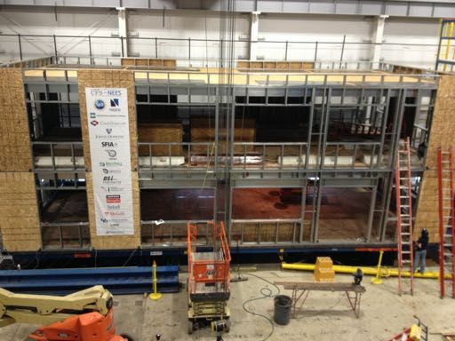
Timeline – Good news!

                            I have been assured
                            that once we ascend
                            these stairs that we
                            will be right on track
                            for full-scale shake
                            table testing!

                        Escher, Relativity (1953)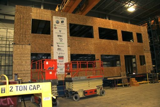
CFS-NHERI Details
Who   NSF, UCSD, JHU, UMass, CFSRC, AISI, SFIA (more)
      NIST through NEHRP ASCE 41 companion project led by Matthew Speicher providing one year of
      related support to JHU, huge win that we have mutual goals at this time
What NSF $996K (+158K supplement approved)-funded project + Industry-funded Diaphragm project
      advancing design of the seismic/lateral response of mid-rise CFS-framed buildings
Where UCSD including NHERI shake table facility (LHPOST), JHU and UMass labs
Why   CFS framing shows great potential as a modern building system; however, the response is different
      from skeletal framing systems and new understanding and tools are needed, particularly to
      quantify and utilize the large contributions from non-designated seismic systems and the details
      required to pushup story heights
How   Experiments from the fastener scale up through full-scale 10 story shake table tests supported by
      modeling across the same scales and extending to larger suite of CFS-framed archetype buildings
When Overall - Original: May 2017- April 2020, now May 2017 – April 2022 (summer 2022 expected)
      Delays have been a challenge for the whole team.
               Wall-line dynamic tests: time on table truncated;
               Companion diaphragm tests: time on shake table delayed;
               UCSD shake table upgrade to 6 DOF, shuttered table, and now further slowed by COVID
      Table scheduled to re-open Spring 2021, CFS-NHERI follows two other delayed projects,
      We are told tentatively on the shake table December 2021/January 2022

        For everyone’s planning purposes – January 2022 is the target for 10-story test.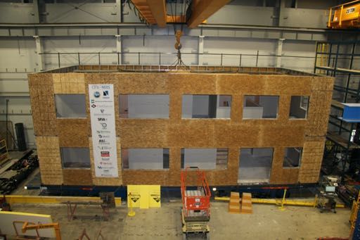
cfsrc.org for more updates and details
Appendix E: Analysis Results of State-of-the-art, phase 1, 2D, model a (A1-2D-a)
CFS-NHERI scope of efforts
E.1 Model description
23/06/2015 2500 6
This set of state-of-the-art 2D models features subpanel bracing models of shear walls,
explicit models of hold-downs, bare steel framing of gravity walls, and rigid leaning
Roof Specimen
2000
CFS-HUD Project (@UCSD): To 54 mils joists, 7/16 in OSB, #8 sheathing screws
Engage Industry, Enable modeling
columns. Interplay between addresswall
different for
thelines
need
is notfor understanding
allowed the
in 2D models, representing 1500
Load (lb)
earthquake and post-earthquake fire
develop and support better building
the effect of flexible diaphragms.design
Seismic mass is lumped at leaning column nodes. The 1000
response of mid-rise CFS-framed
codes and standards lateral displacement and shear buildings,
wall capacity a (δunique
(0.2VnA), 0.2Vmultidisciplinary
nA) from test is utilized to 500
project was recently conducted at the
for seismic CFSF
(a) EPP
determine the stiffness of elastic material and the first
NHERI@UCSD shake pointtable
on the backbone
betweencurve of 00 0.2 0.4 0.6 0.8 1
• Technical Adv. Board April
Pinching4 material of shear wall andFigure
bracing. JulyE-12016. Fastener
(a) to (d)Central to this models
illustrate OpenSees
photo credit: Rogers (in)
Displacement
research was the system-level cantilever response
• Testing standards of South, North, East and West elevations. and live fire testing of a full-
earthquake
• Modeling standards hysteretic models
(b) Pinching4
scale six-story CFS-framed building
Figure 3-10: Nonlinear models for shear walls
wall (a)took upPinching4
EPP (b)
al. 2012).
to 4% before collapse and the drift at peak capacity were around 2% (Liu et
with steel-sheet shear walls (Fig. 4). In a
• Seismic design proposals
The nominal shear capacity per unit width, vn, is found from AISI-S213 (American Iron
and Steel Institute 2009) and for a given wall of width b the nominal shear capacity,
three-week test program, the building
Since the backbone curve of Pinching4 material for truss elements modeling shear walls
Vn=bvn. From Table C2.1-3 for 43 or 54 mil studs and track with 7/16 in. OSB on one-
are characterized
side and #8 fasteners spaced 6 in. o.c. vn=825 plf. (Note, using
this is the lower shear
bound wall test results from Liu et al. (Liu et al. 2012), the
specified
was subjected to nine earthquake tests of
building’s
code strength and is conservatively selected for the peak capacity
models developed determined
here; further, this from pushover analysis (Figure 6-2) coincides with
photo credit: Easterling
increasing intensity. Earthquake motions
~2% story drift. However, even though the Pinching4 backbone curve of shear wall
were scaled to imposeshear service,walls and wall line response
121 elements has a post-peak drop of capacity close to 40%, the pushover curve of the
design, Experimental Program
building drops very little after the peak due to the interaction of other components with
shear walls. Pushover analysis shows that the ductility of A1-3D-SD-a model of Phase 1
June 2015
Provide new and MCE demands onto Wall lineth& (diaphragm) tests
the test
building is not small, so the proposed drift limit for collapse is set as 4% (marked by the
validated wall linebuilding.
models Following the(b) MCE (7 )
vertical dash line in Figure 5-1) to avoid being too conservative.
Archetype Designs
(a) South North
motion test, live fire tests were 4.5
IDA of A1 3D SD a model, P695 record suite
Benjamin W. Schafer Benjamin W. Schafer
• Archetypes create our conducted on the earthquake-damaged
! !
4
First Mode Spectural Acceleration Sa (g)
Collapse Limit State
building at two selectSystem identification.. PhaseFull 2b mid-rise shaking
earthquake. At 100% scale this is essentially equal to the Design Basis Earthquake (DBE) per
3.5
earthquake. At 100% scale this is essentially equal to the Design Basis Earthquake (DBE) per
floors,
U.S. with
standards [21,44]. the 3
Phase 2a U.S. standards [21,44]. Phase 2c
system definition intent of simulating room compartment Fig. 5. Construction of the CFS-HUD test building on the
2.5
2
NHERI@UCSD shake table, stick framing at (a-b) lower floor
• Opportunity to be
1.5
post-earthquake fire scenarios. The 1
0.5
and (c-d) pre-fabricated construction at upper floors
(a) East lower most floor (level 2) was subject to
forward leaning
0
(b) West 0 1 2 3 4 5
Max interstory drift (%)
6 7 8
Figure E-1: A1-2D-a model
fire damage across 75% of its floor plan. Finally, the test building was subjected to two post-fire
Figure 6-1: IDA result of A1-3D-SD-a model
• Help define the bounds building models earthquake IDA tests, including a low amplitude ‘aftershock’ and an extreme near-fault MCE-target intensity 274
motion. The performance of the test building was documented with four types of monitoring systems: still
of what is possible and Improved tools, engine for new
cameras, >40 video cameras, >250
(a) Phase analog
1 completed building sensors,(b) aPhase(a)global Phase
Phase
2e completed positioning
2d
1 completed
buildingbuilding system (GPS)
Phase
(b) Phase 2e and
2e completed buildinga suite of
what needs developing design methods, better unmannedR, Rs aerial vehiclesFigure (UAVs). The later (GPS and UAV) were essential in monitoring the global
Benchmark whole
Figure
drift9.during
CFS-NEES
building,
seismicFull-scale
excitationbuilding testing and measured drift during seismic excitation
shake table tests
9. CFS-NEES Full-scale building testing and measured
permanent structural displacement, The Phase 1 buildingas was well as subsequent
deconstructed providing
new building to the same specifications, Phase 2, wasnew
to The
the 100%physical
Phase
building to
constructed
1 building
Canoga
on the
Park
the same
monitoring
was deconstructed
testing and a
shakespecifications,
from
subsequent to thedifficult vantage
100% Canoga Park testing and points
tables. The Phase 2, was constructed on the shake tables. The
a
(e.g. top down views of10,the Phase 2 test specimen).
structure continued construction past the Phase
engineered
in Phase 2b the gravity exterior walls were externally
2 structure
system.
10, insheathed,
Phase 2binthe
Ascontinued
depicted
gravity
Phase 2c the
construction
in Figure
exterior
past the engineered system. As depicted in Figure
walls were externally sheathed, in Phase 2c the interior
interior
System identification face of results prior
the exterior walls to with gypsum,face
were sheathed
walls and staircases were installed, and finally in Phase
in of the exterior
Phase
walls 2eand(also
2d all thewalls
staircases
werepartition
interior
were 9b)
see Figure
sheathed with gypsum, in Phase 2d all the interior partition
installed, and finally in Phase 2e (also see Figure 9b) exterior
exterior
and after 405 each significant DensGlass was test on the
installed. DensGlass was installed.
building specimen (fire or earthquake) are
presented in Fig. 5. These results show the
increase in system period and associated
damping at important modes of the 29
structure. The system period is seen to PHASE 1/2a PHASE 1/2a PHASE 2b
PHASE 1/2a PHASE 1/2a PHASE 2b
STRUCTURAL SYSTEM ONLY STRUCTURAL SYSTEM ONLY ADDSYSTEM
STRUCTURAL EXTERIOR OSB
ONLY STRUCTURAL SYSTEM ONLY ADD EXTERIOR OSB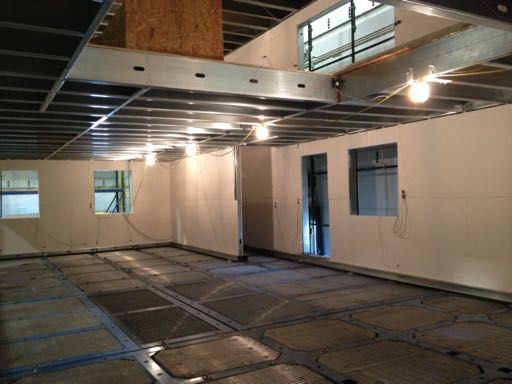
Industry Collaboration and Standards
   Engage Industry,          • Fall 2017 kickoff workshop established trajectory for
 develop and support
 codes and standards
                               initial work. Also participants settled on an overall
   for seismic CFSF            standard of effort for CFS-NHERI objectives: focus on
• Technical Adv. Board         the best we know today + stretch to a little more
• Testing standards
• Modeling standards           (definitively beyond the code) state-of-the-art ++.
• Seismic design proposals
                             • Summer 2019 workshop clarified the push to
                               demonstrate CFSF buildings above code limits. i.e.
                               >65 ft tall, with a 10-story building as the rallying cry
                             • Summer 2020, finally with clarity on the shake table
                               timing – re-engaged with Clark Dietrich Building
                               Systems to provide an industry designed and
                               detailed 10-story CFSF building for high seismic
A
B
C
D
E
F
H
Shear&Wall Width&(Ft)
A 21
forward leaning
B 21
system definition
C 5
D 10
E 4
• Opportunity to be
Provide new
F 20
H 6
• Archetypes create our
of what is possible and
what needs developing
Archetype Designs
• Help define the bounds
Fig.4. The unified archetype building plan, elevation and shear wall layout.
•
The buildings designed in this study (based on the unified archetype buildin
are sited in Irvine, CA (site class D) and are 116 ft × 48 ft in plan with a typic
story height of 9.44 ft (Note, the original example for the archetype is a fou
story building). To design the buildings with different amounts of stories, t
following parameters were presumed in accordance to ASCE 7 (ASCE 2010
Importance Factor, Ie=1, Acceleration Parameter at short periods, Ss=1.3
Spectral Response Acceleration Parameter at a period of 1s, Sl=0.5, Short Peri
Site-Coefficient, Fa=1 and Long-Period Site Coefficient, Fv=1.5.
In general, the structural details of the building including lateral force resisti
system (LFRS), and gravity framing is selected to be similar to the CFS-NE
archetype building. Accordingly, ledger framing is assumed and the LF
mainly consists of Type I OSB (7/16 in.) sheathed shear walls, as designated
Fig. 4. Each shear wall is anchored by hold-downs at the ends only on t
foundation, and ties or strap at floor levels are used to provide chord st
continuity. The parameters R (Response Modification Coefficient), Ωo (Ove
Archetype Building Design
Strength Factor) and Cd (Deflection Amplification) were determined to be 6.5,
testing and fully designed…
and 4, respectively, per ASCE 7 Table 12.14-1 as Light-frame (cold-form
steel) walls sheathed with wood structural panels rated for shear resistance
• Minimal design of gravity system
CFS joists with cementitious panels
• CFS-NHERI Team Designs (4 and 10 story)
5
• Complete design of gravity system and diaphragms –
• Sited in Orange County, SDC D, Cat. II, SDS=0.93g
• Large stud packs in lower floors, Tie rods across floors
• Ledger framing, and ledger used as chord and collectors
• 600S250-97’s, 30 mil sheet, #12 @ 2 in. o.c., fully blocked
• CFS steel sheet shear walls, HSS as needed for chord studs
ClarkDietrich Building Sys (10 story) (complete in July)
• CFS steel sheet shear wall (> AISI S400 tables – see next slide)
• Review of team design and CD design with industry advisory
building archetype details, this building will then be sliced for
group latter this summer/early Fall to be used to establish final
Archetype Design Detail: Extended* Steel Sheet Shear Wall Tables
Table E2.3-1 EXTENDED
Nominal Shear Strength [Resistance] (vn) per Unit Length for Seismic for Shear Walls with Steel Sheet

                             UNBlocked Single Sided Steel Sheet                                                                 Double Sided Steel Sheet (not blocked)
  Sheet       aspect                                                        stud                          Sheet      Wall                                                     stud
thickness      ratio                 Fastener spacing (in.)               thickness      Fastener       thickness    size                Fastener spacing (in.)             thickness   Fastener
   (in.)                     6           4          3             2          (in.)           #             (in.)    (ftxft)       6          4          3           2          (in.)        #
  0.018        2:1 a       390                                             0.033            8            2 x .014    4x8                   2063                    3063       0.068        10
  0.027        2:1   a
                           647          710         778         845        0.033            8            2 x .014    4x8                   2042                    3166       0.097        10
                                                                                                         2 x .019    4x8                   2765                    4231       0.097        10
               2:1 a                   1000        1085        1170        0.043            8
                                                                                                         2 x .019    4x8                   3087                    4783       0.097        12
  0.030        2:1 a       910         1015        1040        1070        0.043            8
                     a
  0.033        2:1         1050        1170        1235        1305        0.043            8                                           Center Ply Steel Sheet
                2:1 a                                           1870         0.054          8             Sheet      Wall                                                     stud
a - max aspect ratio 2:1 per AISI S400-15, blue entries are from existing AISI S400-15                  thickness    size                Fastener spacing (in.)             thickness   Fastener
                                                                                                           (in.)    (ftxft)      6           4          3           2          (in.)        #
                            Fully Blocked Single Sided Steel Sheet                                        0.033      4x8        5537       6328                   10895       0.097        10
  Sheet         Wall                                                        stud                          0.033      4x8                   8017                               0.097        10
thickness       size                 Fastener spacing (in.)               thickness      Fastener         0.043      4x8        9011                                          0.097        12
   (in.)       (ftxft)       6           4          3             2          (in.)           #            0.043      4x8                   10107                              0.097        12
  0.030        2:1 a                                           1355        0.043           10             0.043                            9936                               0.097        10
  0.033        2:1 a                                           1505        0.043           10
                                                                                                    Blue are from Table E2.3-1 in AISI-S400-15
                2:1 a                                           2085         0.054         10
   0.030        2x8         1355        1818        1938        2559         0.054                  Black are extensions based on the following studies:
                6x8         1365        1713        1962        2110         0.054                  Rizk R, Rogers CA (2017) "Higher strength cold-formed steel framed / steel shear walls for mid-rise
                8x8         1279        1664        2030        2307         0.054                  construction", Research Report, Dept. of Civil Engineering & Applied Mechanics, McGill
                4x8                                             2464         0.068
                                                                                                    Santos V, Rogers CA (2017) "Higher capacity cold-formed steel sheathed and framed shear walls for mid-
                4x8                                             2805         0.097                  rise buildings: Part 1", Research Report, Dept. of Civil Engineering & Applied Mechanics, McGill
a - max aspect ratio 2:1 per AISI S400-15, blue entries are from existing AISI S400-15              University, Montreal, Canada.
*We summarized recent testing of Rogers et al. and developed                                        Briere V, Rogers CA (2017) "Higher capacity cold-formed steel sheathed and framed shear walls for mid-
extended tables for use in our in-house designs. Note some tests have                               rise buildings: Part 2", Research Report, Dept. of Civil Engineering & Applied Mechanics, McGill
                                                                                                    University, Montreal, Canada.                                                                            9
undesirable failures, particularly in the chord studs and track…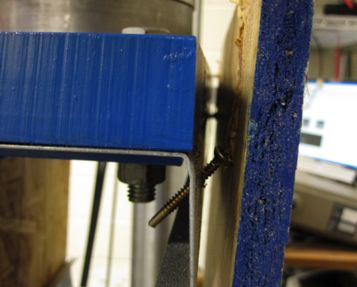
Fastener Testing                                                              2500

                                                                                  2000

• Enables mechanistic modeling                                                    1500

                                                                      Load (lb)
• Explores ductility sources at most basic level                                  1000

                                                                                  500

• Lots of different methods used in the                                             0
                                                                                         0     0.2        0.4           0.6   0.8        1

 literature: lap-shear, two studs pulled apart,    Fastener                                      photo credit: Rogers (in)
                                                                                                       Displacement

                                                                   cantilever response
 two decks slipped past one another, two
 studs shearing fasteners, more
• Cyclic steel-to-steel fastener testing aligned                                             photo credit: Easterling

 with AISI S400 steel sheet shear walls, or        shear walls and wall line response
                                                       Wall line & (diaphragm) tests
 with steel sheet fastened to HSS – does not
 exist, JHU completed testing these
 configurations in the winter of 2020              System identification..                                                     Full mid-rise shaking

• UMass also completed missing wood-to-
 steel and tested sureboard-to-steel fastener
 response and developed unique database of
 nominally identical fastener response                        Benchmark whole building, shake table tests

                                                                                                                                    29
JHU Fastener Testing
Test Matrix
Steel Sheet Thickness (inch)
Framing Thickness (inch)
0.013 (Fy~50 ksi) 0.019 (Fy~33 ksi) 0.03 (Fy~33 ksi)
(Fy~50 ksi)
#8 #10 #12 #8 #10 #12 #8 #10 #12 PAF
0.054 7 7 7 7 7 7
CFS 0.068
0.097 7 7 7 10 7
2 x 0.097 7 7 7 7 7
2 Ply CFS
2 x 0.118 7
0.188 7 7
HSS
0.375 7
Fastener testing existing (monotonic and cyclic)
Perimeter fasteners Simple lap shear Steel sheet sheathed shear wall testing existing (monotonic, cyclic, and/or dynamic)
get exercised in shear, testing rig is selected, Combination of fastener and steel thickness which is not applicable based on TN of CFSEI
but also the sheet but cyclic protocol 7 test series: 1 Monotonic ; 3 Asymmetric Cyclic Buckling Away ; 3 Asymmetric Cyclic Buckling
buckles and buckles the this sheet Towards 10 test series: 3 Tension Only Cyclic + 7 test series
potentially pries on every cycle in addition
the fastener head to pulling the lap in
reducing connection shear. External • No overlap between available fastener tests and shear wall tests
ductility and possibly support is used to • Severe lack of data for thicker CFS studs
strength, this control buckling
influence needs to be direction of the thin • No data relative to mid-ply SS shear walls
in cyclic testing. steel sheet ply. • No data relative to HSS thickness ranges, nor use of PAFsJHU Fastener Testing Sample Results “Sheet”: 13 mil 30 mil 30mil “Stud”: 54 mil 54 mil 3/16 in. Fastener: #8 #8 PAF
Diaphragm Testing 23/06/2015
Roof Specimen
6
• Partner efforts with UMass 54 mils joists, 7/16 in OSB, #8 sheathing screws
• To be discussed in next presentation!
Fastener photo credit: Rogers
cantilever response
photo credit: Easterling
shear walls and wall line response
Experimental Program June 2015
Wall line & (diaphragm) tests
System identification.. Full mid-rise shaking
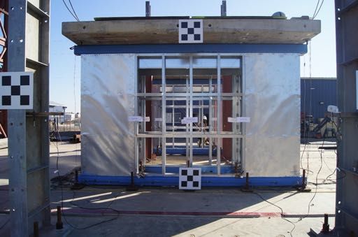
Benchmark whole building, shake table testsWall Line Testing
• 16 ft length specimens with 4 foot length
combinations of shear walls, gravity walls,
and gravity walls with openings
• Dynamic (shake table) and cyclic tests now Fastener photo credit: Rogers
complete, results write up in final stages cantilever response
photo credit: Easterling
shear walls and wall line response
Wall line & (diaphragm) tests
System identification.. Full mid-rise shaking
Benchmark whole building, shake table testsScope of UCSD Wall line testing
NHERI@UC San Diego Shake Table Tests (Complete) – summarized at July 2019 workshop
• Features
• Significant superimposed mass
• Mix of shear walls and gravity walls
• Consideration of finishes
• Consideration of Type I vs II detailing
• Inclusion of tie rods and impact on
chord studs
• Examination of fastener patterns
• Practical details – but beyond AISI
S400 scope
• Preliminary Findings
Powell Lab @UC SanDiego Cyclic Tests (Complete) – completed in last year • Overall good performance
• Challenges w/ blocking details and
performance
• Non-negligible boundary
deformations in stud and track
• Significant impact of finish, for both
shear wall and gravity wall
• Limited impact of steel only gravity
walls, additive strength in gypsum
gravity walls
• Reports forthcoming soon
15Backbone Curves (Quasi-static tests) finish effect
Peak Strength
8000plf
(/8ft SW len.)
4000plf
(/16ft wall len.) Rogers test
Rogers test
• Isolated 4’ x 8’ SS SW from
Rogers et al.
vpeak = 2800 plf
• 16’ x 8’ wall line with 8’ SS
SW, 8’ gravity wall,
finished vpeak = Vpeak/8’
vpeak = 8000 plf
16Shake Table Testing
• January 2022 expected table time CFS-HUD Project (@UCSD): To
address the need for understanding the
earthquake and post-earthquake fire
• 10 story focus – break through the height limit
response of mid-rise CFS-framed
(Follows CLT mass timber 10 story testing onbuildings,
table..)a unique multidisciplinary
project was recently conducted at the
• ClarkDietrich completing benchmark 10 story design shake Central
NHERI@UCSD
April and July 2016. Fastener
table between
to this photo credit: Rogers
• Floor and diaphragm system, pretty dialed-in withresearch
ledger- was the system-level cantilever response
framed CFS joists and USG structural panels, UL fire assembly
earthquake and live fire testing of a full-
scale six-story CFS-framed building
• Gravity wall system, conventional CFS stud walls,withUL assembly
steel-sheet shear walls (Fig. 4). In a
• Steel sheet shear walls with HSS chord studs. Multi-story test program, the building
three-week
was subjected to nine earthquake tests of
detailing in CD design still not finalized, known soon. photo credit: Easterling
increasing intensity. Earthquake motions
• We will use this design to engage with industry and scaled to imposeshear
wereeliminate service,walls design, and wall line resposne
pain points and focus on key opportunities for improvement
and MCE demands in onto Wall theline test& (diaphragm) tests
th
the final tested configuration. building. Following the MCE (7 )
motion test, live fire tests were
• Timeline
Benjamin W. Schafer Benjamin W. Schafer
conducted on the earthquake-damaged
! !
building at two selectSystem identification.. PhaseFull 2b mid-rise shaking
earthquake. At 100% scale this is essentially equal to the earthquake.
Design BasisAt 100% scale this
Earthquake is essentially
(DBE) per equal to the Design Basis Earthquake (DBE) per
floors,
U.S. with
standards [21,44]. the Phase 2a U.S. standards [21,44]. Phase 2c
•
Fall 2020 – Industry Iteration, final system choices
intent of simulating room compartment Fig. 5. Construction of the CFS-HUD test building on the
NHERI@UCSD shake table, stick framing at (a-b) lower floor
post-earthquake fire scenarios. The
•
Winter 2020/21 – Final building design, Slice for testing
lower most floor (level 2) was subject to
and (c-d) pre-fabricated construction at upper floors
•
Spring 2021 – Predictive modeling, Procurement fire damage across 75% of its floor plan. Finally, the test building was subjected to two post-fire
earthquake tests, including a low amplitude ‘aftershock’ and an extreme near-fault MCE-target intensity
•
Summer 2021 – Final Details, Drawings motion. The performance of the test building was documented with four types of monitoring systems: still
cameras, >40 video cameras, >250 analog sensors,(b) aPhase(a)global positioning system (GPS) 2e andbuildinga suite of
•
Fall 2021 – Delivery and Construction unmanned aerial vehiclesFigure
(a) Phase
(UAVs).
1 completed building
The later (GPS and
2e Phase
Phase
completed
UAV)
2d
1 completed
buildingbuilding
were essential in monitoring the global
Phase
(b) Phase 2e completed
Benchmark whole
Figure
drift9.during
CFS-NEES
building,
seismicFull-scale
excitationbuilding testing and measured drift during seismic excitation
shake table tests
9. CFS-NEES Full-scale building testing and measured
•
January 2022 - Testing permanent structural displacement,
(e.g. top down views of10,the
The Phase 1 buildingas
Phase 2 test specimen).
structure
was well
continued
as subsequent
deconstructed
construction
providing
new building to the same specifications, Phase 2, wasnew
past the
to The
the 100%physical
Phase
building to
constructed
Phase
engineered 2
1 building
Canoga
on the
structure
system. As
monitoring
was
Park
the same
deconstructed
testing and a
shakespecifications,
continued
depicted
from
subsequent to thedifficult vantage
100% Canoga Park testing and points
tables. The Phase 2, was constructed on the shake tables. The
construction
in Figure past the engineered system. As depicted in
a
Figure
in Phase 2b the gravity exterior walls were externally10, insheathed,
Phase 2binthe gravity
Phase 2c theexterior walls were externally sheathed, in Phase 2c the interior
interior
System identificationface of results prior
the exterior walls to with gypsum,face
were sheathed
walls and staircases were installed, and finally in Phase
in of the exterior
Phase
walls 2eand(also
2d all thewalls
staircases
werepartition
interior
were 9b)
see Figure
sheathed with gypsum, in Phase 2d all the interior partition
installed, and finally in Phase 2e (also see Figure 9b) exterior
exterior
and after each significantDensGlass was test on the
installed. DensGlass was installed.
building specimen (fire or earthquake) are
presented in Fig. 5. These results show the
increase in system period and associated
damping at important modes of the
structure. The system period is seen to PHASE 1/2a PHASE 1/2aPHASE 1/2a PHASE 2b
PHASE 1/2a PHASE 2b
STRUCTURAL SYSTEM ONLY STRUCTURAL SYSTEM ONLY ADDSYSTEM
STRUCTURAL EXTERIOR OSB
ONLY STRUCTURAL SYSTEM ONLY ADD EXTERIOR OSBAppendix E: Analysis Results of State-of-the-art, phase 1, 2D, model a (A1-2D-a)
CFS-NHERI scope of efforts
E.1 Model description
This set of state-of-the-art 2D models features subpanel bracing models of shear walls,
explicit models of hold-downs, bare steel framing of gravity walls, and rigid leaning
Engage Industry, Enable
columns. Interplaymodeling for
between different wall lines is not allowed in 2D models, representing
develop and support better building
the effect of flexible diaphragms.design
Seismic mass is lumped at leaning column nodes. The
codes and standards lateral displacement and shear wall capacity (δ(0.2VnA), 0.2VnA) from test is utilized to
for seismic CFSF
(a) EPP
determine the stiffness of elastic material and the first point on the backbone curve of
• Technical Adv. Board Pinching4 material of shear wall bracing. Figure E-1 (a) to (d) illustrate OpenSees models Fastener photo credit: Rogers
cantilever response
• Testing standards of South, North, East and West elevations.
• Modeling standards hysteretic models
(b) Pinching4
Figure 3-10: Nonlinear models for shear walls
wall (a)took upPinching4
EPP (b)
al. 2012).
to 4% before collapse and the drift at peak capacity were around 2% (Liu et
• Seismic design proposals
The nominal shear capacity per unit width, vn, is found from AISI-S213 (American Iron
and Steel Institute 2009) and for a given wall of width b the nominal shear capacity,
Since the backbone curve of Pinching4 material for truss elements modeling shear walls
Vn=bvn. From Table C2.1-3 for 43 or 54 mil studs and track with 7/16 in. OSB on one-
are characterized
side and #8 fasteners spaced 6 in. o.c. vn=825 plf. (Note, using
this is the lower shear
bound wall test results from Liu et al. (Liu et al. 2012), the
specified
building’s
code strength and is conservatively selected for the peak capacity
models developed determined
here; further, this from pushover analysis (Figure 6-2) coincides with
~2% story drift. However, even though the Pinching4 backbone curve of shear wall
photo credit: Easterling
121 elements has a post-peak drop of capacity close to 40%, the pushover curve of the
building drops very little after the peak due to the interaction of other components with
shear walls and wall line resposne
shear walls. Pushover analysis shows that the ductility of A1-3D-SD-a model of Phase 1
Provide new building is not small, so the proposed drift limit for collapse is set as 4% (marked by the
Wall line & (diaphragm) tests
validated wall line models
vertical dash line in Figure 5-1) to avoid being too conservative.
Archetype Designs
(a) South (b) North
IDA of A1 3D SD a model, P695 record suite
4.5
• Archetypes create our
4
First Mode Spectural Acceleration Sa (g)
Collapse Limit State
System identification.. Full mid-rise shaking
3.5
3
system definition 2.5
2
• Opportunity to be
1.5
1
0.5
forward leaning
0
(a) East 0 1 2 3 4 5
Max interstory drift (%)
6 7 8
(b) West
Figure E-1:
Figure 6-1: IDA A1-2D-a
result of A1-3D-SD-a model model
• Help define the bounds building models IDA 274
of what is possible and Improved tools, engine for new
what needs developing design methods, better R, Rs
Benchmark whole building, shake table tests
405Appendix E: Analysis Results of State-of-the-art, phase 1, 2D, model a (A1-2D-a)
Modeling
E.1 Model description
This set of state-of-the-art 2D models features subpanel bracing models of shear walls,
explicit models of hold-downs, bare steel framing of gravity walls, and rigid leaning
Enable
columns. Interplaymodeling for
between different wall • inHysteretic
lines is not allowed 2D models, representingmodels
better building
the effect of flexible diaphragms.design
• Characterization of fastener tests (complete)
Seismic mass is lumped at leaning column nodes. The
(a) EPP
• Characterization of wall line tests (in progress)
lateral displacement and shear wall capacity (δ(0.2VnA), 0.2VnA) from test is utilized to
determine the stiffness of elastic material and the first point on the backbone curve of
• Characterization of past shear wall tests (method established)
Pinching4 material of shear wall bracing. Figure E-1 (a) to (d) illustrate OpenSees models
of South, North, East and West elevations.
hysteretic models
(b) Pinching4
• Steel sheet shear wall models
• High fidelity models (initial analyses and results complete, need to revisit
Figure 3-10: Nonlinear models for shear walls
wall (a)took upPinching4
EPP (b) to 4% before collapse and the drift at peak capacity were around 2% (Liu et
al. 2012).
The nominal shear capacity per unit width, vn, is found from AISI-S213 (American Iron
and Steel Institute 2009) and for a given wall of width b the nominal shear capacity,
with new fastener data, then can move to predictive modeling)
Since the backbone curve of Pinching4 material for truss elements modeling shear walls
Vn=bvn. From Table C2.1-3 for 43 or 54 mil studs and track with 7/16 in. OSB on one-
are characterized
side and #8 fasteners spaced 6 in. o.c. vn=825 plf. (Note, using
this is the lower shear
bound wall test results from Liu et al. (Liu et al. 2012), the
specified
building’s
code strength and is conservatively selected for the peak capacity
models developed determined
here; further, this from pushover analysis (Figure 6-2) coincides with
121
~2% story drift. However, even though the Pinching4 backbone curve of shear wall
elements has a post-peak drop of capacity close to 40%, the pushover curve of the • Fastener-based model, only appropriate for in-plane rigid sheathing, can be
employed in wall-line models for gypsum board gravity walls (this year)
building drops very little after the peak due to the interaction of other components with
shear walls. Pushover analysis shows that the ductility of A1-3D-SD-a model of Phase 1
building is not small, so the proposed drift limit for collapse is set as 4% (marked by the
validated wall line models
• Wall line models
vertical dash line in Figure 5-1) to avoid being too conservative.
(a) South (b) North
IDA of A1 3D SD a model, P695 record suite
4.5
4
• Benchmarking against CFS-NHERI wall line tests (initiating)
First Mode Spectural Acceleration Sa (g)
Collapse Limit State
3.5
3
2.5
• Partnership with NIST, model large variety of typical wall lines to better
2
1.5
1
establish CFSF system level overstrength and ductility and means to predict,
0.5
0
(a) East 0 1 2 3 4 5
Max interstory drift (%)
6 7 8
(b) West
Figure E-1: A1-2D-a model
this work initiating now, need industry involvement for wall lines…
Figure 6-1: IDA result of A1-3D-SD-a model
building models IDA 274
Improved tools, engine for new
design methods, better R, Rs
• Building models
• Only simplified models to date. Predictive models after wall line models.
405Conclusions • CFS-NHERI has followed a nonlinear time history path to its current status. With significant testing now complete and a clear plan in place the team is • driving towards the January 2022 shake table testing • quantifying overstrength and ductility in complete CFSF buildings • Industry engagement has been ramping up since March when CD was re- engaged for a full 10-story building design, and will ramp up further this Fall as the team • seeks feedback and iterates on 10-story design • develops a series of typical building wall line archetypes (with NIST) • engages with partners for establishing complete specimen procurement • Significant work remains, but CFS-NHERI is providing a path towards increasing height limits, increasing shear wall capacities, developing and disseminating better details, and providing a seismic design framework that is consistent with the behavior of repetitively framed structures
You can also read