A Tip-Tilt and Piston Detection Approach for Segmented Telescopes - MDPI
←
→
Page content transcription
If your browser does not render page correctly, please read the page content below
hv
                photonics

Letter
A Tip-Tilt and Piston Detection Approach for Segmented
Telescopes
Shun Qin and Wai Kin Chan *

                                                Tsinghua-Berkeley Shenzhen Institute, Tsinghua Shenzhen International Graduate School,
                                                Shenzhen 518055, China; shun.qin@sz.tsinghua.edu.cn
                                                * Correspondence: chanw@sz.tsinghua.edu.cn

                                                Abstract: Accurate segmented mirror wavefront sensing and control is essential for next-generation
                                                large aperture telescope system design. In this paper, a direct tip–tilt and piston error detection
                                                technique based on model-based phase retrieval with multiple defocused images is proposed for
                                                segmented mirror wavefront sensing. In our technique, the tip–tilt and piston error are represented
                                                by a basis consisting of three basic plane functions with respect to the x, y, and z axis so that they can
                                                be parameterized by the coefficients of these bases; the coefficients then are solved by a non-linear
                                                optimization method with the defocus multi-images. Simulation results show that the proposed
                                                technique is capable of measuring high dynamic range wavefront error reaching 7λ, while resulting
                                                in high detection accuracy. The algorithm is demonstrated as robust to noise by introducing phase
                                                parameterization. In comparison, the proposed tip–tilt and piston error detection approach is much
                                                easier to implement than many existing methods, which usually introduce extra sensors and devices,
                                                as it is a technique based on multiple images. These characteristics make it promising for the
                                                application of wavefront sensing and control in next-generation large aperture telescopes.

                                                Keywords: segmented mirror; wavefront sensing; tip–tilt; piston; model-based phase retrieval


                                                1. Introduction
Citation: Qin, S.; Chan, W.K. A
Tip-Tilt and Piston Detection
                                                     In the past, the aperture size was the main factor that impeded the development of
Approach for Segmented Telescopes.
                                                high-resolution telescopes. The segmented mirror scheme paves a new way to designing
Photonics 2021, 8, 3.                           a very large aperture telescope, achieving diffraction-limited optical imaging. The de-
https://dx.doi.org/10.3390/                     ployment of the Keck telescope [1,2], in which the primary mirror consists of 36 hexagon
photonics8010003                                mirrors and the diameter reaches 10 m, demonstrated the success of the solution of a
                                                segmented mirror in the application of a large aperture telescope. Nowadays, the James
Received: 12 November 2020                      Web Space Telescope (JWST) [3,4], the successor of the Hubble Telescope built for deep
Accepted: 22 December 2020                      space exploration, also employs a segmented mirror to design the primary mirror with an
Published: 25 December 2020                     advanced accurate control device and algorithm.
                                                     Generally, cophasing contains several steps: segment searching, coarse alignment,
Publisher’s Note: MDPI stays neu-               coarse phasing, and fine phasing [5]. The Jet Propulsion Laboratory (JPL) developed a
tral with regard to jurisdictional claims       multi-step stacking process to realize cophasing for JWST based on combined techniques
in published maps and institutional             such as phase retrieval and dispersive fringe sensing. The wavefront is calculated by
affiliations.                                   a multiple image-based phase retrieval algorithm [6], then the tip–tilt error is obtained
                                                by least-squares fitting with the Hexikes polynomials for each segment. The fine wave-
                                                front of the whole aperture is then measured by phase retrieval. Following the cophasing
Copyright: © 2020 by the authors. Li-
                                                solution developed by JPL, more cophasing techniques were developed during the last
censee MDPI, Basel, Switzerland. This           decade. In 2013, Fernández-Valdivia et al. developed a tip–tilt detection technique based
article is an open access article distributed   on the Van Dam and Lane algorithm with two defocus images measured by a geomet-
under the terms and conditions of the           ric sensor [7]. In 2014, Cheetham et al. introduced Fizeau Interferometric Cophasing
Creative Commons Attribution (CC BY)            of Segmented Mirrors, which is capable of phasing mirror segments to interferometric
license (https://creativecommons.org/           precision without involving exceptional hardware in order to realize fine cophasing of
licenses/by/4.0/).                              the JWST with a single algorithm [8]. In 2016, Greenbaum et al. developed an in-focus

Photonics 2021, 8, 3. https://dx.doi.org/10.3390/photonics8010003                                              https://www.mdpi.com/journal/photonics
Photonics 2021, 8, 3                                                                                                     2 of 11

                       wavefront sensing technique using non-redundant mask-induced pupil diversity for JWST
                       cophasing, without introducing focus diversity [9]. In 2017, Potiron et al. realized the fine
                       cophasing of segmented aperture telescopes based on an analysis scheme to the signal of
                       a Zernike wavefront sensor, which enabled the sensor to retrieve a segment piston and
                       tip–tilt unambiguously [10]. More recently, a focal-plane wavefront sensing technique was
                       proposed for measuring and correcting the low-wind effect [11].
                            Nonetheless, among existing cophasing techniques, phase retrieval is considered to
                       be one of the best options for wavefront sensing and control for next-generation large
                       aperture telescopes for its high accuracy and simplicity of implementation [12]. Actually,
                       the wavefront sensing with phase retrieval technique has drawn lots of attentions and
                       became more and more mature since the success of its application with the Hubble Tele-
                       scope aberration detection [13]. Due to its high performance and simplicity, JWST is also
                       mainly based on phase retrieval for accurate wavefront sensing and control. Even though
                       the phase retrieval algorithm developed by JPL has been validated much more robust than
                       the classical phase retrieval techniques such as the Gesrchberg-Saxton (GS) [14] or hybrid
                       input–output (HIO) algorithm [15], by introducing phase diversity [16], simulation has
                       shown that the alternative projecting-based phase retrieval technique requires a very high
                       signal-to-noise ratio (SNR) image to guarantee high accuracy and efficiency; in contrast,
                       the model-based phase retrieval technique seems to be much more accurate and robust
                       to noise in practice [17]. In this paper, we employ a model-based phase retrieval tech-
                       nique [18] to directly detect the tip–tilt error in a segmented mirror without introducing
                       any extra sensor or device such as the abovementioned cophasing techniques. In Section 2,
                       we review the model-based phase retrieval and show the implementation of the non-linear
                       optimization-based phase retrieval algorithm with multiple defocused images for robust
                       and efficient wavefront sensing. In Section 3, we apply the proposed multiple image-based
                       phase retrieval algorithm for tip–tilt and piston detection for a segmented mirror with a
                       basis consisting of three basic planes. In Section 4, the proposed technique is validated by
                       simulation. Finally, we summarize our work in Section 5.

                       2. Model-Based Phase Retrieval Based on Multiple Defocus Images
                            The model-based method solves the phase retrieval problem with a parametrized
                       method and optimization algorithm such as the Newton method or Gauss–Newton algo-
                       rithm. Mathematically, a wavefront can be represented by an orthogonal basis such as
                       Zernike polynomials [19,20], by which a phase can be parameterized so that the phase
                       retrieval problem can be solved by a non-linear optimization method easily. The pupil
                       function can be expressed as

                                                                                   N
                                                          P( x, y) = A· exp(i     ∑ qn ·Ψn )                                (1)
                                                                                  n =1

                       where q = (q1 , q2 , · · · , q N ) and Ψ = (Ψ1 , Ψ2 , · · · , Ψ N ) T are a coefficient vector and an ap-
                       propriate polynomial basis vector, respectively. According to diffraction theory, the formed
                       image in the focal plane can be represented by

                                                               G (u, v) = | F [ P( x, y)]|2                                 (2)

                       where F denotes Fourier transformation. Based on the least-squares estimation method,
                       the objective function with respect to q can be written as

                                                           L                        2
                                                 E(q) =   ∑ {| F[ P(q)]|2j − Ij }       , j = 1, 2, · · · , L               (3)
                                                           j

                       where I denotes the image measured by the detector, j is the index of the pixel, and L
                       denotes the length of the data points.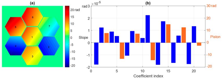
Photonics 2021, 8, 3                                                                                                  3 of 11

                            In practice, the single image-based phase retrieval methods are very easy to stagnate
                       and cannot guarantee global convergence. To avoid this problem, multiple images can
                       be introduced, e.g., defocus images. Figure 1 shows the principle of multiple defocus
                       image-based phase retrieval. It uses not only the focal plane image, but also several extra
                       diverse images, i.e., defocused images. In this case, Equation (1) is rewritten as

                                                                             N
                                                      P( x, y) = A· exp(i   ∑ qn · Ψn + φ)                               (4)
                                                                            n =1

                       where φ denotes the introduced known diverse phase. For defocus diversity, the introduced
                       phase can be approximated with the following:

                                                                       x 2 + y2

                                                               φ = π∆z                                                   (5)
                                                                          λf2

                       where λ is the wavelength of the light, ∆z is the defocus distance, and f is the focal length
                       of the lens. As more images are utilized, the algorithm becomes much more effective and
                       robust. Assuming M images are used, then the total error can be written as

                                                        E = E1 (q) + E2 (q) + · · · E M (q)                              (6)

                            Theoretically, minimizing the above objective function results in an optimal solution
                       that satisfies Equation (2), with which the phase can be reconstructed with the corre-
                       sponding basis. Basically, the minimization problem can be solved by existing non-linear
                       optimization methods. However, many existing non-linear optimization techniques are
                       very easy to stagnate due to the serious nonlinearity of the phase retrieval problem. We here
                       employed the Levenberg–Marquardt (LM) algorithm, which is theoretically intended for
                       solving least-squares problems and has been demonstrated as more accurate and robust to
                       noise than a Fourier iteration method such as the Modified GS algorithm [17].

                       Figure 1. The principle of wavefront sensing with multiple defocused images. A point object at
                       infinity is imaged by the optical imaging system, and the system point spread function (PSF) is
                       formed on the camera, with which the wavefront in the pupil plane could be retrieved algorithmically.
                       As phase retrieval is based on the coherent light diffraction theory, it usually needs a monochromatic
                       source or narrow band filter in practice.

                            Assuming the least-squares based objective function is represented as

                                                                                   L
                                                          E(q) = r (q)T r (q) =    ∑ r2j (q)                             (7)
                                                                                    j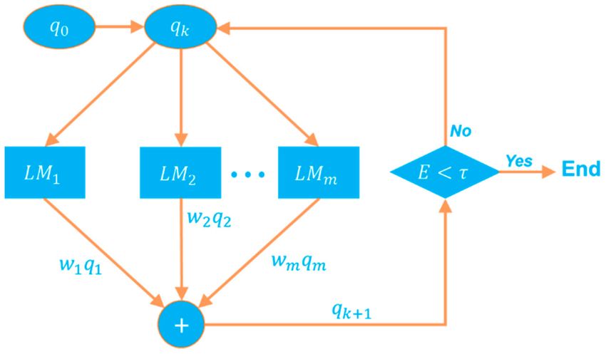
Photonics 2021, 8, 3 4 of 11
where j = 1, 2, · · · , L denotes the index of data points and q = (q1 , q2 , . . . , q N ), r denotes
the difference between the estimated result by the model function and the observed data,
the iterative formula of the LM algorithm [21] can be written as
−1
qk+1 = qk − J T J + µΛ · gk (8)
where k denotes the index of iteration. The gradient with respect to the objective function
is written as g(q) = J (q) T r (q), and the Jacobian matrix is defined as
∂r1 ∂r1
∂q1 · · ·
∂q N
.. ..
J (q) = . . .. (9)
.
∂r L ∂r L
···
∂q1 ∂q N
For model-based phase retrieval problems, the residual error is written as r = G (q) − I,
where G (q) is the image calculated by Equation (2), and the partial derivative of r with
respect to q, i.e., the column vector in the Jacobian matrix, can be derived easily as
∂r (q) ∂[ G (q) − I ]
=
∂q ∂q
∂[ F ( P) F ∗ ( P)]
=
∂q (10)
∂[ F ( P)] ∗ ∂[ F ∗ ( P)]
= F ( P) + F ( P)
∂q ∂q
= F ( P·iΨ) F ∗ ( P) + F ( P) F ∗ ( P·iΨ)
with which LM can be implemented easily.
As mentioned above, single image-based phase retrieval usually suffers from the
stagnation problem, especially for large dynamic range phase retrieval. Therefore, more
images usually are introduced to improve robustness in practice, and the most convenient
way would be to employ defocus images. We introduced a simple multi-LM algorithm
to solve the phase retrieval problem with multiple defocus images. Namely, each LM
algorithm calculates the parameter q with an image independently and the results are then
combined with a weighting technique to guarantee global convergence.
Assuming that M defocused images are taken for phase retrieval by the proposed
multi-LM algorithm, we propose an effective weighting technique as follows: First calculate
the weight for each calculated parameter vector qm as
γ
εm
wm = M γ (11)
∑m =1 ε m
where ε m is a quantity used for calculating the weighting value, and γ is the constant
controlling the penalty degree. The simplest way to determine the weight for each resulting
parameter by LM algorithm is to use the residual error calculated by each LM as ε. However,
the calculated images by algorithm may not match the measured ones in amplitude, which
could result in faulty weight. To avoid this problem, we introduced the maximum of
correlation between two images, which is written as
ε = max( IEst ⊗ IDet ) (12)
where IEst is the image estimated by the algorithm, IDet denotes the detected image, and
max means taking the maximum of the correlation map between two images. The correla-
tion map could be calculated by a general image correlation technique, such as Pearson
coefficients, but we employed cosine similarity, which can be calculated by fast Fourier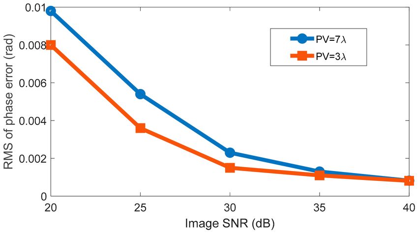
Photonics 2021, 8, 3                                                                                                 5 of 11

                       transformation (FFT) for the sake of efficiency. In this case, the value γ = 2 is good option
                       empirically. When the value of all weights are determined, qk is updated as

                                                                      ∑ m =1 w
                                                                        M            m
                                                           q k +1 =              m q k +1                             (13)

                            The principle of the algorithm is be described in Figure 2. The algorithm contains two
                       loops: the inner loop and outer loop. In the inner loop, each LM algorithm calculates q
                       independently with a common input, i.e., qk . Then the results output by all LM algorithms
                       are combined to generate qk+1 in the outer loop. This process is repeated until the stop
                       condition is satisfied.

                       Figure 2. The principle of the multiple image-based LM algorithm, where q0 denotes the initial guess
                       of the parameter to be solved, LMm denotes the mth image processed by LM algorithm, and τ denotes
                       the error tolerance.

                       3. Model-Based Tip–Tilt and Piston Detection for Segmented Mirror
                            In practice, there are many forms of segmenting that actually share similar modeling
                       in analysis. For simplicity, we took the hexagon segmented mirror, one of the most popular
                       segmenting fashions. In the case of hexagon segmented mirror wavefront sensing, let us
                       just consider tip–tilt and piston phase error retrieval. In this case, each segment of the
                       phase can be represented as

                                                          ψ( a, b, c) = aX + bY + cZ                                  (14)

                       where X, Y, and Z are the normalized bases of each phase segment, which are just as
                       Figure 3 shows, and a, b, and c are their respective coefficients. X and Y are defined by
                       planes x − z = 0 and y − z = 0, respectively, and Z is defined by plane z = 1, with the
                       support defined by a segment.

                       Figure 3. The basis for a single segment. (a) the base component on x-axis, (b) the base component
                       on y-axis, (c) the base component on z-axis.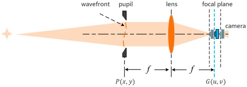
Photonics 2021, 8, 3 6 of 11
As there is no overlap between segments, the phase of the whole mirror is the sum of
the phase of all segments. Thus, the whole wavefront can be written as
N
Θ( a, b, c) = ∑ θ ( a n , bn , c n ) (15)
n =1
where n is the index of the segment, N is the total amount of segments, and ( a, b, c) is
the vector of [ a1 , a2 , · · · a N , b1 , b2 , · · · b N , c1 , c2 , · · · c N ], which contains all the parameters to
be solved. From the above formula, it can be seen that the function of each segment has
three parameters, and there are 3N parameters in total for the whole mirror that need
to be calculated. Similar to Equation (3), the objective function for the case herein can
be written as
L
→ → →
E a, b, c = ∑ [G(ψ) − I ]2j (16)
j =1
L 2
= ∑ F2 [ A· exp(iθ ( a, b, c))] − I
j
(17)
j =1
where I denotes the image measured by the detector, and the sum is applied to all pixels
with index j. Obviously, the process of solving Equation (17) is just the same as the
case of model-based wavefront sensing analyzed above. Similar to the popular Zernike
polynomial-based parameterized technique, a set of bases, i.e., the segmented tip–tilt and
piston, is used to parameterize the wavefront of the whole segment mirror here. Therefore,
the tip–tilt and piston error sensing for a segmented mirror also can be calculated like a
general model-based phase retrieval algorithm with high accuracy.
4. Simulation
We validated the proposed algorithm by simulation with the case of hexagon segment
mirror tip–tilt error detection. The ground truth wavefront and corresponding coefficients
are just as Figure 4 shows. In this segmented mirror phase retrieval simulation, we consider
a segmented mirror with 7 segments, just as Figure 4a shows. The peak-to-valley (PV) value
of the whole wavefront was set to 7λ, which contained tip–tilt error and piston error, just as
Figure 4b shows. The slope and the piston error of each segment was generated randomly.
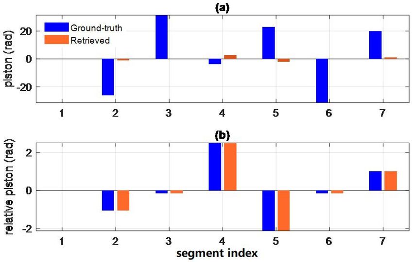
Four out-of-focus images were simulated based on the model represented by Equation (2).
Poisson noise was applied to all image data; the noisy images used for simulation are just
as Figure 5 shows.
Figure 4. The ground truth phase error and coefficients. In figure (a), the hexagon segment is
simulated according to the real size of JWST, with a diameter for each segment of 1.3 m and an image
size of 256 × 256. The index of each segment is as the numbering shown. In figure (b), the bar in
blue denotes the tip–tilt error and the orange is the piston error. The coefficient index is defined as
(a1 , b1 , c1 , a2 , b2 , c2 , . . . a7 , b7 , c7 ), subscripted by the segment index.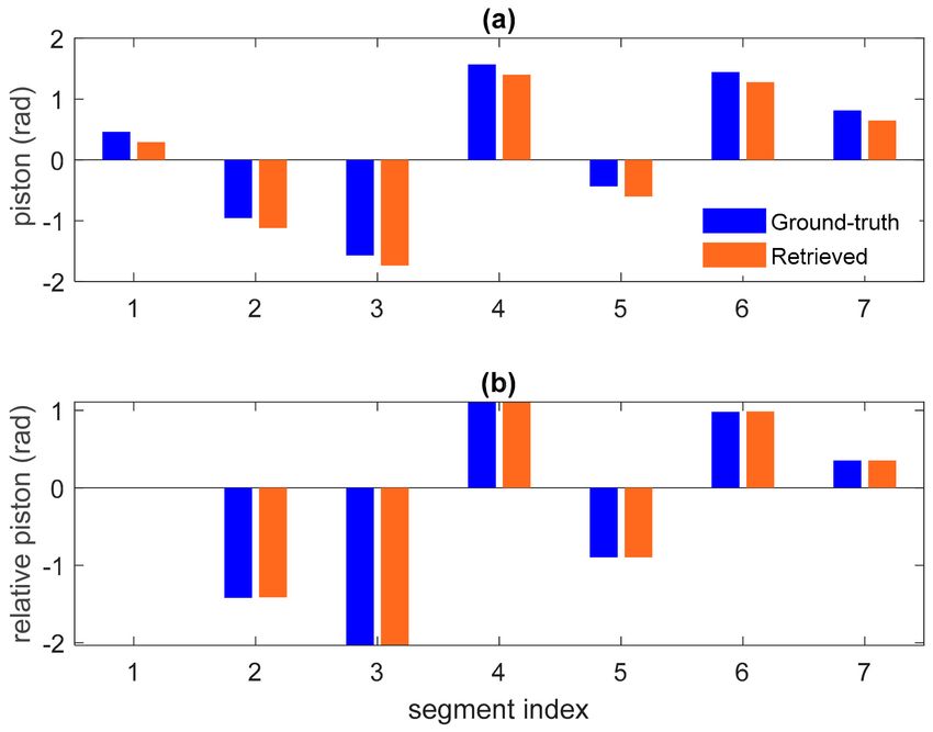
Photonics 2021, 8, 3                                                                                            7 of 11

                       Figure 5. Simulated images taken from defocus planes: (a) defocus at −71.75 mm, (b) defocus
                       at 71.75 mm, (c) defocus at −53.81 mm, and (d) defocus at 53.81 mm. The minus symbol means
                       defocusing along light-traveling direction.

                             We then used our algorithm to retrieve the tip–tilt and piston error from the measured
                       images shown in Figure 5, for which the image SNR was 30 dB on average. The simulation
                       was implemented on the general computer without graphic card acceleration; the computer
                       configuration was i7-6700HQ CPU@2.6GHz, 16 G RAM, 64-bit Windows 10 OS, and the
                       platform for algorithm coding and testing was based on MATLAB R2018b. As Poisson noise
                       is the dominant noise in modern digital cameras [22], it was applied to all simulated images
                       for testing the algorithm’s performance, such as the efficiency and robustness to noise.
                             Figure 6 shows the performance of the proposed phase retrieval algorithm when
                       used to retrieve the tip–tilt and piston error of the segmented mirror shown in Figure 4.
                       The simulation shows very accurate results in tip–tilt error, but a completely different result
                       in piston error. In fact, due to the 2π ambiguity problem, the piston cannot be determined
                       uniquely when the PV is larger than one wavelength for the image-based phase retrieval
                       algorithm. Therefore, the phase retrieval method based on intensity can only retrieve
                       the real piston error within one wavelength. Nonetheless, it shows that the proposed
                       algorithm is still valuable for direct accurate tip–tilt and piston error detection without
                       introducing extra complex sensors or devices, based on the result of the coarse cophasing
                       step, in which the large initial tip–tilt and piston error is usually effectively corrected by
                       another technique. Actually, combining the proposed image-based wavefront techniques
                       with some existing techniques could be a good choice to realize fast and accurate large
                       dynamic-range cophasing in practice.
                             Figure 7 shows the performance of the proposed phase retrieval algorithm to noise.
                       It shows that the wavefront error decreased with the increasing of image SNR. The retrieved
                       wavefront was quite accurate even for low image SNR; for the image with SNR = 30 dB,
                       which corresponds to a gray level of several thousand—a quite general signal amplitude
                       level in practice—the resulting root mean square (RMS) of the wavefront already reached
                       about 0.2% radian. This denotes that the model-based phase retrieval technique is able to
                       achieve very high accuracy for wavefront sensing. It also shows that the lower dynamic
                       range (PV ≤ 3λ) resulted in higher accuracy, but the difference of resulting accuracies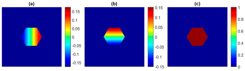
Photonics 2021, 8, 3                                                                                               8 of 11

                       between the high dynamic range and the low dynamic range were not large, which
                       indicates that noise level is the main factor that impacts accuracy. Therefore, the image SNR
                       should be as high as possible to guarantee high performance wavefront sensing in practice.

                       Figure 6. Difference between the retrieved coefficients and those of the ground truth.

                       Figure 7. The RMS of the retrieved phase error caused by tip–tilt error vs. difference noise level.
                       The RMS is calculated by taking the RMS of the difference between the phase calculated by the real
                       tip–tilt and that calculated by the estimated tip–tilt by an algorithm with zero pistons.

                            To clearly show the performance of piston detection by the proposed image-based
                       phase retrieval technique, we also implemented simulations on small and large piston
                       sensing. In simulation, all tip–tilt errors were set to zero, i.e., only pistons were taken
                       into consideration. Then the same algorithm was used to calculate the values of all
                       21 coefficients. The initial value for all parameters was set to zero. Figures 8 and 9 show
                       the simulation results of the piston retrieval by the proposed phase retrieval algorithm.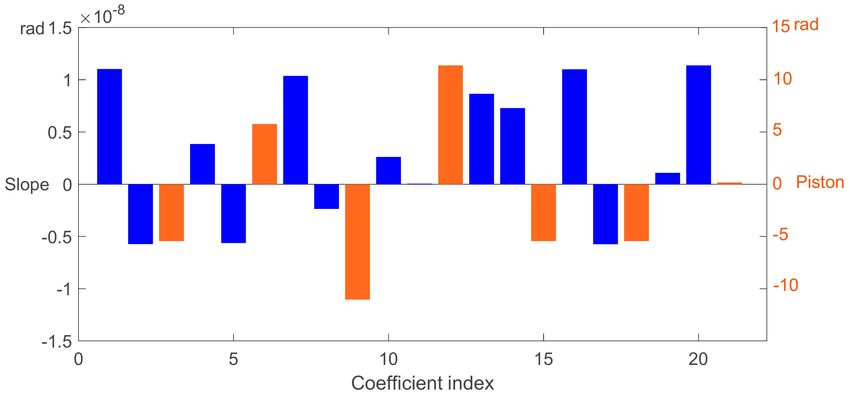
Photonics 2021, 8, 3                                                                                                        9 of 11

                       Figure 8. Small piston retrieval: (a) the retrieved piston vs. the ground truth piston and (b) the retrieved
                       relative piston vs. the relative ground truth piston. In (b), the first segment is set as the reference.

                       Figure 9. Large piston retrieval: (a) the retrieved piston vs. the ground truth piston and (b) the
                       retrieved relative piston vs. the relative ground truth piston. In (b), the first segment is set as the
                       reference, and the relative piston is wrapped.

                            Figure 8a shows that the piston could be retrieved successfully for small pistons,
                       however, an extra background piston was introduced. This makes sense, since a back-
                       ground piston denotes all segments shift as a whole, namely, there is no relative shifting
                       between them, which has no impact on the imaged Fourier modulus pattern. Figure 8b
                       shows the comparison between the retrieved relative piston and the ground truth relative
                       piston, which shows quite high accuracy. The simulations show that when the piston error
                       was small, the piston errors could be retrieved correctly, otherwise the calculated pistons
                       involved a 2π phase ambiguity problem. It was found that the algorithm only worked
                       well for relative pistons lower than half a wavelength with zero as the initial value. In fact,
Photonics 2021, 8, 3 10 of 11
there was no guarantee that the exact piston could be retrieved by an image-based phase
retrieval algorithm mathematically; however, for a small piston error with an appropriate
initial value, the algorithm was still able to retrieve the real piston successfully.
Figure 9 shows the simulation result in the case of large piston retrieval. Similar to the
case of small piston retrieval, the pistons were retrieved quite well. Figure 9a shows that the
ground truth piston was quite high, where the PV reached 10λ, and the retrieved pistons
were quite different from the ground truth due to the 2π ambiguity problem. The retrieved
pistons were constrained within a wavelength of dynamic range.
Even though it suffered from the 2π ambiguity problem for large pistons, our simula-
tion shows that the proposed algorithm was still capable of calculating an optimal solution,
even for PV higher than 10λ, with high accuracy. The wrapped retrieved relative pistons
were actually the same as those of the ground truth, just as Figure 9b shows. Therefore,
the calculated piston value would be useful for large accurate detection within one mea-
surement, combining the result with another piston detection technique, e.g., a piston
detection sensor and the technique of sensor fusion. Therefore, it can believed that the
proposed technique still has potential for fast, accurate large piston error detection.
5. Discussion
In this article, we proposed a direct tip–tilt and piston error detection approach for a
segmented mirror in large-aperture telescope system design. We show that the tip–tilt and
piston error can be represented by the combination of three basic plane functions, which
are used as the basis for parameterizing the segmented mirror tip–tilt and piston error.
The problem then is solved by the well-known LM algorithm with multiple defocus images.
The simulation shows that the proposed technique results in accurate tip–tilt error detection,
even for a low SNR image, and is able to retrieve a high dynamic range wavefront. Even
though a large piston could not be retrieved successfully due to the ambiguity problem for
the image-based phase retrieval problem when the PV of the wavefront is higher than one
wavelength, it is still very valuable for accurate tip–tilt error detection and small piston
detection in application, and we believe that the proposed technique still has potential
for fast, accurate large piston detection. The advantage of the proposed phase retrieval
algorithm is that it is precise, efficient, and very easy to implement. However, it should be
pointed out that the complexity of the proposed algorithm will increase with the increasing
of number of segments and the number of the bases used to represent the wavefront of a
single segment. As the cost of computing is becoming cheaper and the power of computers
is increasing, we believe that the proposed technique is a still a good solution for segmented
mirror wavefront sensing with any amount of segments in the future. In future work,
we will focus on a fast, accurate piston detection approach with the proposed technique
and look for and use more appropriate basis to represent more phase error beyond tip–tilt
and piston for each segment.
Author Contributions: Conceptualization, S.Q.; methodology, S.Q.; software, S.Q.; validation, S.Q.;
formal analysis, S.Q.; investigation, S.Q.; resources, S.Q.; data curation, S.Q.; writing—original draft
preparation, S.Q.; writing—review and editing, S.Q.; visualization, S.Q.; supervision, W.K.C.; project
administration, S.Q. and W.K.C.; funding acquisition, S.Q. and W.K.C. All authors have read and
agreed to the published version of the manuscript.
Funding: This research was funded by the China Postdoctoral Science Foundation, grant number
2020M680556; the National Natural Science Foundation of China, grant number 71971127; and Hylink
Digital Solutions Co., Ltd., grant number 120500002.
Data Availability Statement: Not applicable.
Conflicts of Interest: The authors declare no conflict of interest.Photonics 2021, 8, 3 11 of 11
References
1. Barinaga, M. Keck telescope. Nature 1987, 330, 5. [CrossRef]
2. James, M.B.; Jong, R.A.; Kenneth, A.; Barton, V.B.; Donald, T.G.; Randall, L.H.; Brooks, J.; Holger, E.J.; Thomas, C.K.; Claire, E.M.;
et al. Wavefront control system for the Keck telescope. In Proceedings of the Adaptive Optical System Technologies, Kona, HI,
USA, 23–26 March 1998; Volume 3353, pp. 517–521.
3. Greenhouse, M. The James Webb Space Telescope: Mission Overview and Status. In Proceedings of the 2019 IEEE Aerospace
Conference, Big Sky, MT, USA, 2–9 March 2019; pp. 1–13.
4. Acton, D.S.; Towell, T.; Schwenker, J.; Swensen, J.; Shields, D.; Sabatke, E.; Klingemann, L.; Contos, A.R.; Bauer, B.; Hansen, K.
Demonstration of the James Webb Space Telescope commissioning on the JWST testbed telescope. In Proceedings of the Space
Telescopes and Instrumentation I: Optical, Infrared, and Millimeter, Orlando, FL, USA, 24–31 May 2006; p. 62650R.
5. Acton, D.S.; Atcheson, P.D.; Cermak, M.; Kingsbury, L.K.; Shi, F.; Redding, D.C. James Webb Space Telescope wavefront sensing
and control algorithms. In Proceedings of the Optical, Infrared, and Millimeter Space Telescopes, Glasgow, UK, 21–25 June 2004;
pp. 887–896.
6. Basinger, S.; Redding, D.; Lowman, A.; Burns, L.; Liu, K.; Cohen, D. Performance of wavefront sensing and control algorithms on
a segmented telescope testbed. In Proceedings of the UV, Optical, and IR Space Telescopes and Instruments, Munich, Germany,
29–31 March 2000; pp. 749–756. [CrossRef]
7. Fernández-Valdivia, J.J.; Sedano, A.; Chueca, S.; Gil, J.; Ridriguez-Ramos, J.M. Tip-tilt restoration of a segmented optical mirror
using a geometric sensor. Opt. Eng. 2013, 52, 056601. [CrossRef]
8. Cheetham, A.; Cvetojevic, N.; Norris, B.; Sivaramakrishnan, A.; Tuthill, P. Fizeau interferometric cophasing of segmented mirrors:
Experimental validation. Opt. Express 2014, 22, 12924–12934. [CrossRef] [PubMed]
9. Greenbaum, A.Z.; Sivaramakrishnan, A. In-focus wavefront sensing using non-redundant mask-induced pupil diversity. Opt. Ex-
press 2016, 24, 15506–15521. [CrossRef] [PubMed]
10. Janin-Potiron, P.; N’Diaye, M.; Martinez, P.; Vigan, A.; Dohlen, K.; Carbillet, M. Fine cophasing of segmented aperture telescopes
with ZELDA, a Zernike wavefront sensor in the diffraction-limited regime. Astron. Astrophys. 2017, 603, A23. [CrossRef]
11. Bos, S.; Vievard, S.; Wilby, M.; Snik, F.; Lozi, J.; Guyon, O.; Norris, B.; Jovanovic, N.; Martinache, F.; Sauvage, J.-F.; et al.
On-sky verification of Fast and Furious focal-plane wavefront sensing: Moving forward toward controlling the island effect at
Subaru/SCExAO. Astron. Astrophys. 2020, 639, A52. [CrossRef]
12. Egron, S.; N’Diaye, M.; Laginja, I.; Brady, G.; Soummer, R.; Lajoie, C.-P.; Montmerle, A.; Michau, V.; Choquet, E.; Ferrari, M.; et al.
James Webb Space Telescope Optical Simulation Testbed V: Wide-field phase retrieval assessment. In Proceedings of the Space
Telescopes and Instrumentation 2018: Optical, Infrared, and Millimeter Wave, Austin, TX, USA, 10–15 June 2018; p. 106983N.
[CrossRef]
13. Fienup, J.R.; Marron, J.C.; Schulz, T.J.; Seldin, J.H. Hubble Space Telescope characterized by using phase-retrieval algorithms.
Appl. Opt. 1993, 32, 1747–1767. [CrossRef] [PubMed]
14. Gerchberg, R.W. A practical algorithm for the determination of phase from image and diffraction plane pictures. Optik 1972, 35,
237–246.
15. Fienup, J.R. Phase retrieval algorithms: A comparison. Appl. Opt. 1982, 21, 2758–2769. [CrossRef] [PubMed]
16. Gonsalves, R.A. Phase retrieval and diversity in adaptive optics. Opt. Eng. 1982, 21, 215829. [CrossRef]
17. Mao, H.; Zhao, D. Alternative Phase-Diverse Phase Retrieval algorithm based on Levenberg-Marquardt nonlinear optimization.
Opt. Express 2009, 17, 4540–4552. [CrossRef] [PubMed]
18. Gonsalves, R.A. Phase retrieval from modulus data. JOSA 1976, 66, 961–964. [CrossRef]
19. Wang, J.Y.; Silva, D.E. Wave-front interpretation with Zernike polynomials. Appl. Opt. 1980, 19, 1510–1518. [CrossRef] [PubMed]
20. Andersen, T.B. Efficient and robust recurrence relations for the Zernike circle polynomials and their derivatives in Cartesian
coordinates. Opt. Express 2018, 26, 18878–18896. [CrossRef] [PubMed]
21. Lourakis, M.I.A. A brief description of the Levenberg-Marquardt algorithm implemented by levmar. Found. Res. Technol. 2005, 4, 1–6.
22. Ling, Z.; Hui, Z.; Hongwei, Y.; Xuewu, F.; Xiaopeng, X. Modified phase diversity technique to eliminate Poisson noise for
reconstructing high-resolution images. In Proceedings of the 9th International Symposium on Advanced Optical Manufacturing
and Testing Technologies: Advanced Optical Manufacturing Technologies, Chengdu, China, 16 January 2019; p. 108380R.You can also read