Chi: A Scalable and Programmable Control Plane for Distributed Stream Processing Systems
←
→
Page content transcription
If your browser does not render page correctly, please read the page content below
Chi: A Scalable and Programmable Control Plane for
               Distributed Stream Processing Systems

                     Luo Mai1 , Kai Zeng2 , Rahul Potharaju2 , Le Xu3 , Steve Suh2 , Shivaram Venkataraman2 , Paolo Costa1,2 ,
                             Terry Kim2 , Saravanan Muthukrishnan2 , Vamsi Kuppa2 , Sudheer Dhulipalla2 , Sriram Rao2

                                                    1 Imperial     College London, 2 Microsoft, 3 UIUC
            1 luo.mai11@imperial.ac.uk, 2 {kaizeng,          rapoth, stsuh, shivaram.venkataraman, pcosta, terryk, sarmut, vamsik, sudheerd,
                                                        sriramra}@microsoft.com, 3 lexu1@illinois.edu

ABSTRACT                                                                                  Fully achieving the benefits promised by these online systems,
Stream-processing workloads and modern shared cluster environ-                          however, is particularly challenging. First, streaming workloads
ments exhibit high variability and unpredictability. Combined with                      exhibit high temporal and spatial variability, up to an order of mag-
the large parameter space and the diverse set of user SLOs, this                        nitude compared to the average load [27, 31]. Second, large shared
makes modern streaming systems very challenging to statically con-                      clusters exhibit high hardware heterogeneity and unpredictable con-
figure and tune. To address these issues, in this paper we investigate                  current usage. Third, modern streaming systems expose a large pa-
a novel control-plane design, Chi, which supports continuous mon-                       rameter space, which makes tuning hard, even for the most experi-
itoring and feedback, and enables dynamic re-configuration. Chi                         enced engineers. Further, different users and jobs have a diverse set
leverages the key insight of embedding control-plane messages in                        of Service Level Objectives (SLOs), leading to divergent configura-
the data-plane channels to achieve a low-latency and flexible con-                      tion settings. Addressing these issues requires introducing contin-
trol plane for stream-processing systems.                                               uous monitoring and feedback as well as dynamic re-configuration
  Chi introduces a new reactive programming model and design                            into all aspects of streaming systems, ranging from query planning
mechanisms to asynchronously execute control policies, thus avoid-                      and resource allocation/scheduling to parameter tuning. We call
ing global synchronization. We show how this allows us to easily                        the system layer in charge of such control mechanisms the control
implement a wide spectrum of control policies targeting different                       plane, to distinguish it from the data plane (the layer in charge of
use cases observed in production. Large-scale experiments using                         data processing).
production workloads from a popular cloud provider demonstrate                            Through our interaction with product teams and cloud operators,
the flexibility and efficiency of our approach.                                         we identified the following requirements that a control plane should
                                                                                        satisfy. First, it should be possible to define new custom control op-
PVLDB Reference Format:                                                                 erations, tailored to different scenarios [24]. Second, this should be
Luo Mai, Kai Zeng, Rahul Potharaju, Le Xu, Steve Suh, Shivaram Venkatara-               achieved with only minimal effort by the developers and through
man, Paolo Costa, Terry Kim, Saravanan Muthukrishnan, Vamsi Kuppa,                      a simple and intuitive API to minimize the chance of bugs, which
Sudheer Dhulipalla, Sriram Rao. Chi: A Scalable and Programmable Con-
                                                                                        are particularly challenging to detect in a distributed environment.
trol Plane for Distributed Stream Processing Systems. PVLDB, 11 (10):
1303-1316, 2018.                                                                        Finally, the control overhead should be kept to a minimum, even
DOI: https://doi.org/10.14778/3231751.3231765                                           in the presence of high event throughput and large computation
                                                                                        graphs. This is particularly critical in today’s landscape with differ-
                                                                                        ent cloud providers competing hard to offer the best SLOs to their
1.     INTRODUCTION                                                                     customers. Ideally the control plane should match the data-plane
  Large-scale Internet-service providers such as Amazon, Facebook,                      SLO (usually in the order of seconds or less).
Google, and Microsoft generate tens of millions of data events per                        Unfortunately, to the best of our knowledge, none of the existing
second [5]. To handle such high throughput, they have traditionally                     streaming systems can satisfy all these requirements. Heron [27]
resorted to offline batch systems [21, 13, 4]. More recently, how-                      and Flink [10] have a monolithic control plane that supports only a
ever, there has been an increasing trend towards using streaming                        limited set of predefined control policies (e.g., dynamic scaling and
systems [3, 10, 27, 31] to ensure timely processing and avoid the                       back pressure), and lacks a clean API, which makes it hard for users
delays typically incurred by offline batch systems.                                     to define custom policies. Spark Streaming [41], adopts a Bulk-
                                                                                        Synchronous Parallel (BSP) model [38] in which a set of events is
Permission to make digital or hard copies of all or part of this work for               buffered and processed as a batch. While this allows the system
personal or classroom use is granted without fee provided that copies are
not made or distributed for profit or commercial advantage and that copies              to modify a dataflow between batches, it has limited flexibility due
bear this notice and the full citation on the first page. To copy otherwise, to         to the hard batch boundaries and incurs high overhead due to the
republish, to post on servers or to redistribute to lists, requires prior specific      synchronization and scheduling operations required.
permission and/or a fee. Articles from this volume were invited to present                To overcome the shortcomings of today’s systems and meet the
their results at The 44th International Conference on Very Large Data Bases,            aforementioned requirements, we explore a novel control-plane de-
August 2018, Rio de Janeiro, Brazil.                                                    sign for stream processing systems. Inspired by the idea of punc-
Proceedings of the VLDB Endowment, Vol. 11, No. 10
Copyright 2018 VLDB Endowment 2150-8097/18/06.                                          tuations [37] being used for data operators, we propose embedding
DOI: https://doi.org/10.14778/3231751.3231765

                                                                                     1303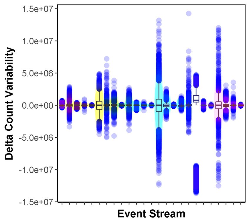
control-plane messages into the data stream. By leveraging the ex- We begin by summarizing the main results of our analysis and
isting data pipeline, control messages can be streamed at low la- discuss the opportunities that arise.
tency and in a scalable fashion, without requiring any ad-hoc mech- Workload Unpredictability: The load on servers ingesting log
anism (§7.2). This seemingly simple approach, however, requires events is highly variable. Fig. 1(a) shows the heat-map of the nor-
support from the underlying streaming infrastructure, to execute malized number of tuples produced per minute across a random
distributed control operations with consistency requirements while subset of streams in our cluster. This shows two important phenom-
minimizing synchronization overhead and enabling an extensible ena. First, as evidenced by the different color patterns across hori-
control programming model. zontal lines, each stream exhibits a unique workload characteristic
In this paper, we describe Chi, a control plane built on this idea of (spatial variability). Second, while some streams are dark (high
embedding control messages in the dataflow to execute low-latency volume) for most time, several streams exhibit burstiness (tempo-
control operations. We introduce a reactive programming model for ral variability), as shown by color spots the same horizontal line.
handling control messages that allows users to encode a number of There are three main reasons for such variability in the log events:
complex control policies. This hides the complex distributed na-
ture of the underlying system and provides developers an intuitive • Heterogenous Workloads: The clusters generating these logs han-
model to understand the boundaries of data events to which the dle a variety of workloads ranging from typical big data jobs
control events are applied. We then design a mechanism to execute (e.g., filter, transform, join) to iterative machine learning work-
these control policies in an asynchronous manner at each opera- loads on behalf of hundreds of teams.
tor, avoiding synchronization and high runtime overhead. We show • Failures & Debugging: Failures are common at large scale. These
that by using our programming model and execution mechanism failures (e.g., networking issues, power issues etc.) generate a
we can efficiently implement a number of control policies ranging large amount of error logs that lead to traffic bursts. In addition,
from basic functionalities such as checkpointing and replay, to ad- when ingestion data is not sufficient, developers temporarily ac-
vanced ones with strong global consistency requirements, such as tivate more verbose logs to perform in-depth debugging, which
continuous monitoring, plan re-optimization, and parameter tuning results in a higher volume stream.
(§5). Finally, we also discuss how our control plane infrastructure • Diverse Stream Semantics: The logs we ingest have diverse se-
can be easily parallelized by having a separate control loop per op- mantics (e.g., info, verbose, debug, error, etc.) with various com-
eration, making the control plane scalable. ponents in the service emitting with different characteristics. A
To validate our claims and evaluate the runtime performance of service at the lowest level (e.g., storage layer) naturally produces
our new control-plane design, we implement Chi on top of Flare, the most logs since most requests involve store I/O transactions.
one of the internal stream processing systems used in our clusters.
To quantify the degree of variability, in Fig. 1(b) we show a box-
Flare is built on top of Orleans [7], a highly efficient distributed
and-whiskers plot with the Y-axis representing the delta in terms
actor framework, and uses Trill [16] as the underlying stream pro-
of event count per minute on a subset of incoming data streams.
cessing engine. While we choose to showcase our approach on top
The height of the box shows the difference in counts between the
of Flare for ease of implementation and deployment on our inter-
25th and 75th percentiles. Beside the significant difference in the
nal clusters, our design is not tied to a specific platform, and with
behavior of each stream, it is worth noting the high range of change
some additional engineering effort, it can be applied to existing
observed within the same stream, denoted by the large number of
systems, including Heron and Flink. Our experimental evaluation,
outliers (blue dots in the figure). For example, for certain event
based on production workloads and industry-standard benchmarks,
streams, the event count can increase by up to tens of millions in
shows that Chi is able to perform reconfiguration for a large state-
just one minute, indicating that a timely response is critical for sus-
ful dataflow in 5.8 seconds on a 32-server cluster. Real-world use
taining load spikes.
cases further show the effectiveness of Chi in helping developers
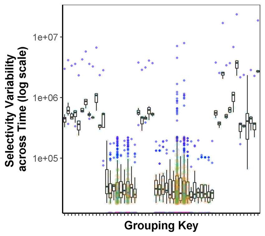
Data Diversity Another key element in determining the optimal
automatically tune critical system parameters and reduce latency
query plan and resource allocation is the data distribution. To an-
by 61%, reducing workload skew during runtime.
alyze its dynamics, we focus on the key selectivity, defined as the
In summary, this paper makes the following contributions:
number of tuples that fall into a particular bucket. To analyze the
• An extensive study of today’s stream-processing workloads through
dynamics of this parameter, in Fig. 1(c) we plot the selectivity of
the logs collected from more than 200,000 production servers.
various grouping keys across time while in 1(d) we plot the selec-
• A scalable and efficient control-plane that allows a streaming
tivity over time across multiple grouping keys. The wide skew in
system to efficiently adapt to changes in workloads or environment.
the selectivity observed in both plots indicates that one-shot query
• A flexible control-plane API that enables developers to easily
planning (e.g., traditional cardinality-based optimizer) either glob-
implement custom control operations.
ally or on a per-key basis will likely be sub-optimal over time.
• Evaluation of our prototype implementation on a 32-server Azure
Multi-tenant control policies: In our production environment, the
VM cluster using production workloads from a cloud service provider
same streaming system is used by many teams. Thus there is a
and across a large set of control operations, including dynamic scal-
big diversity of SLOs across queries from different teams, or even
ing, failure recovery, auto-tuning, and data skew management.
across different queries from the same team, leading to the need
for multiple control policies to be active at the same time. For
2. MOTIVATION instance, we have many customers who are interested in consum-
We performed an extensive measurement study by analysing the ing verbose, info and error logs. While verbose and error logs are
logs generated by more than 200,000 servers of a data-analytics used for debugging, info logs are often used to compute important
cluster of a popular cloud provider. These clusters generate a sig- metrics (e.g., billing metrics). One popular request made by our
nificant amount of log data (10s PB/day), and queries on this data developers has been to provide stronger delivery semantics (e.g.,
are executed by developers for debugging, monitoring, etc. Given exactly-once) for info logs and weaker delivery semantics (e.g.,
the data size, we require a large cluster with adequate network and best-effort, at-least-once) for verbose/error logs. This highlights
compute resources to process data in real time. Our setup is con- the importance of supporting multiple control policies either on a
sistent with a recent analysis of Google production logs [19]. per-stream level or per-tenant level.
1304(a) (b) (c) (d)
Figure 1: (a) Heatmap of a subset of data streams in our ingestion workload. Each horizontal band signifies a unique data stream being ingested, (b) Box plot
representing the variability of delta count (order of millions) per minute (Y-axis) for a subset of incoming data streams (X-axis). (c),(d) Box plot depicting the
selectivity properties of grouping keys used in a streaming join query from production traces. (c) shows selectivity of various grouping keys across time while
(d) shows selectivity variability across the grouping key space.
Multi-tenancy also introduces new opportunities in system man- out incoming channels are source operators; those without outgoing
agement and optimization. In our production traces we observe channels are sink operators.
queries that share a significant overlap in terms of data sources and For instance, consider an example where the user is interested in
operators (e.g., users parsing logs in an identical way). Thus control tokenizing sentences into words, and count the windowed accumu-
policies could look at sharing computation across users or materi- lated count (e.g., per hour) of each word across all sentences in a
alizing intermediate data for later reuse. Further, with insight into data parallel way. This query can be expressed in a LINQ-style
the data streams and workloads, control policies could be used to language as below:
automatically and transparently choose new data layouts (e.g., with
partitioning) and storage engines (e.g., in-memory, database) that E XAMPLE 1 (W ORD C OUNT E XAMPLE ).
can improve execution efficiency. While all these optimizations stream . SelectMany ( line = > Tokenize ( line ))
are well understood in isolation [33, 34, 40, 32], applying them in . GroupByKey ( word = > word )
an integrated manner to optimize the streaming workloads requires . TumblingWindow ( OneHour ). Count ()
flexibility and scalability in the control plane.
Takeaway: Our trace analysis uncovered several interesting char- An instance of a dataflow graph for Example 1 is shown in Stage
acteristics of our workloads – high volume (10s of PB/day), low la- I of Fig 2. Note that operators {R1 , R2 } maintain the accumulated
tency requirement (SLO of seconds), widely diverse (100s of data counts for the words as their mutable local states. These states
streams) and dynamic (due to the nature of services producing these cover a disjoint set of keys, and jointly represent the entire key
logs). Based on this, we can derive the following list of require- subspace, e.g., R1 maintains the accumulated count for all words
ments for the control plane: with the starting letter in the range [’a’-‘l’], while R2 maintains
1. Efficient and extensible feedback-loop controls: Because of those for the range [’m’-’z’].
the diversity of our workloads, it is important to allow users or ap- Dataflow Computation Model: Formally, a dataflow computation
plications to make flexible late-binding decisions on their data pro- is represented as a DAG G(V, E), where V represents the set of op-
cessing logic for optimizing performance. From an extensibility erators, and E, the set of edges connecting the operators, u → v
standpoint, it should be possible to integrate with dedicated com- represents a directed edge from operator u to v. We use {· → v}
ponents (e.g., policy controllers such as Dhalion [24]). to denote the input edges to v, and {v → ·} the output edges from
2. Easy control interface: Since we intend the control plane to v. An operator v ∈ V is described by a triple (sv , fv , pv ), where sv
be used by application developers, having an easier programming is the state of v; fv defines a function that captures the computa-
interface is critical to its adoption. tion run on v, i.e., f : sv , mei ∈{·→v} −→ s0v , {m0eo ∈{v→·} }, meaning
3. Minimal impact on the data plane: The control plane should
a function takes a single input message m, from an input edge ei ,
have limited or no impact on the latency and throughput of the data
and based on the current state sv , it modifies the state of v to a
plane and it should be able to seamlessly cope with high control
new state s0v , and generates one or more messages on a set of out-
frequency and large dataflow graphs.
put edges {m0eo ∈{v→·} }. Operators without input edges are called
sources, and operators without output edges are called sinks. For
generality, we represent the properties associated with v that are not
3. BACKGROUND part of state as pv , e.g., pv can define the maximum memory used
Chi is primarily designed for streaming systems that are based by v. An edge e does not have any state but can hold properties pe ,
on a streaming dataflow computation model. In this section we e.g., the token size of windows before triggering back-pressure.
provide the reader with the necessary background on the streaming
dataflow computation model.
Many existing streaming systems, such as Naiad [30], Stream- 4. DESIGN
Scope [28] and Apache Flink [10] adopt the streaming dataflow The intuition behind embedding the control plane into the data
computation model. In this model, a computation job is represented plane is that this enables re-using the existing, efficient data-plane
as a directed acyclic graph (DAG) of stateful operators, where each infrastructure and offers developers a familiar API to write con-
operator sends and receives logically timestamped events along di- trol operations, i.e., the same used to handle data events. Further,
rected edges. Each operator maintains mutable local state. Upon having control messages directly trailing data events provides a nat-
receiving events, an operator updates its local state, generates new ural way to create custom boundaries between sequences of events.
events, and sends them to downstream operators. Operators with- This makes it easy to implement asynchronous control operations
1305because control messages can be used to capture causal dependen- word counts for the range [‘a’-‘h’], R2 for [‘i’-‘p’], and R3
cies without requiring expensive global synchronization operations. for [‘q’-‘z’]. This reconfiguration needs to maintain the
In this section, we show how we incorporate these principles into consistency of the states. It starts by broadcasting a con-
our control-plane design and provide several examples to describe trol message with the new topology configuration to all the
how we can easily build different control operations on top. We source nodes (→ {M1 , M2 }).
conclude the section by describing some of the more advanced fea- (III) When the source (mapper M1 or M2 ) receives this control
tures of our design and discussing how Chi can be adapted to sup- message, the mapper immediately blocks the input channel
port BSP-style computations. while processing the message, updates its routing table with
the new topology and broadcasts the message downstream
4.1 Overview (→ {R1 , R2 , R3 }).
(IV) When the reducer R1 (or R2 ) receives the control message, it
Chi relies on the following three functionalities. First, channels
blocks the input channel on which the message has been re-
between operators support exactly-once and FIFO delivery of mes-
ceived. When the control messages from all input channels
sages. Back-pressure is used to stop the message propagation when
have been received, it updates its routing table and check-
the buffer of the downstream operator fills up. Second, operators
points its state. Next, it splits the state into two parts: the ac-
process messages one at a time and in the order that they have
cumulated word counts for the range [‘a’-‘h’] and the range
been received. Finally, the underlying engine provides basic op-
[‘i’-‘l’] (or for the ranges [‘m’-‘p’] and [‘q’-‘z’] ) and at-
erator lifecycle management capabilities. Specifically it allows us
taches the state that needs to be handled by R3 , i.e., the word
to start, stop and kill an operator. These functionalities are already
counts for [‘i’-‘l’] (or for [‘m’-‘p’]) to the control message
supported by Flare, our internal streaming system, but they can also
and broadcasts along all output channels (→ {R3 ,C}).
be found in other existing systems [10, 27, 39, 41].
(V) When R3 receives a control message, it blocks that input
Our system design uses dataflow controllers that are responsi-
channel. If the control message originates from R1 (or R2 ),
ble for monitoring dataflow behavior and external environmental
it records the state from the control message. When it re-
changes, and triggering control operations whenever needed. Users
ceives control messages from all input channels, it proceeds
can define control operations, and submit them to the controllers.
to merge all the states received, generate the new state of the
A control operation is carried out through a control loop that is
accumulated word counts for the range [‘i’-‘p’], and install
comprised of a dataflow controller and the dataflow topology itself.
a new function (from the control message) using the new
In general, a control loop consists of three phases: (Phase-I) The
state. Finally, it broadcasts on the output channel (→ C).
controller makes a control decision and instantiates a control op-
(VI) When C receives control messages from all the expected
eration with a unique identifier. A control operation is defined by
sink nodes {R1 , R2 , R3 }, the scale-out operation is completed.
implementing a reactive API (Section §4.2.2), and has control con-
The controller then keeps monitoring the memory usage of
figurations for each operator (e.g., the new topology to scale out the
these operators in the new topology and can decide to scale
dataflow stream). The control operation is serialized into a control
out/in if needed. This forms a feedback-loop control.
message (Section §6). (Phase-II). The control message is broad-
casted by the controller to all source operators of the dataflow. The
control messages then propagate through the dataflow, interleaved
4.2 Control Mechanism
with normal data messages. During the propagation, upon receiv- Next, we describe the core mechanisms underpinning Chi. We
ing a control message, each operator triggers the corresponding start by formally defining the dataflow computation model and ex-
control actions—which can optionally attach additional data (e.g., plain how graph transformations occur. Then, we discuss the con-
the repartitioned state) to the control message—and broadcast the troller and operator APIs and provide an example control operation
control message to all downstream operators. See Section §4.2.2 implementation. We provide a proof of correctness in §4.2.3.
and Section §6 for more implementation details. (Phase-III) In the
end, the sink operators propagate the control messages back to the 4.2.1 Graph Transitions through Meta Topology
controller, and the controller carries out post-processing. Formally, a user control operation C can be modeled as a trans-
We use Fig. 2 to illustrate this process. We consider a case where formation that converts a dataflow execution graph G(V, E) to a
the controller wants to increase the throughput by modifying the new graph G∗ (V ∗ , E ∗ ). For an operator v, such a transformation
topology and adding a new reducer. can change one or more entries in the triple (S, f , P). For an edge
e, such a transformation can optionally change pe . In particular,
(I) At the beginning, there are two map operators {M1 , M2 } and since the operator state S can capture state accumulated over a long
two reduce operators {R1 , R2 } that compute word counting time period, special care is needed to capture the transformation of
for ingested sentences. These operators are stateful. For ex- states during reconfiguration (i.e., G → G∗ ). That is, for v∗ ∈ V ∗ ,
ample, {R1 , R2 } hold the accumulated count for all words, Sv∗ is defined by a transformation function T on one or more nodes
where R1 maintains the counts for all words starting with {v} ⊆ V , i.e., T ({Sv }) = Sv∗ . In cases without ambiguity, we relax
[‘a’-‘l’], and R2 maintains those for [‘m’-‘z’]. The con- the notation and use T −1 (v∗ ) to represent the set {v} ⊆ V whose
troller C is responsible for monitoring the memory usage states Sv∗ depends on.
of all operators and reconfiguring parallelism if needed. To Most existing systems (e.g., [10, 39]) adopt a freeze-the-world
simplify we omit the control messages that collect memory approach to perform the transformation i.e., stop G by appropriate
usage and focus on the parallelism reconfiguration process checkpointing mechanisms, start G∗ , migrate the old checkpointed
in the following discussions. state on G to G∗ and resume the dataflow. However, this would
(II) Once the controller C detects that the aggregated memory likely trigger back-pressure, causing increased latency and loss of
usage of the reducers goes beyond a threshold, it makes throughput, and in turn limits the frequency of execution and ex-
a reconfiguration decision to start a new reducer R3 to in- pressivity of dataflow reconfigurations. Therefore, in the design of
crease memory provisioning. In the new topology, the states Chi we opted for an asynchronous alternative: instead of affecting
of {R1 , R2 , R3 } should be repartitioned so that R1 holds the the transformation directly (i.e., G → G∗ ), we introduce an interme-
1306Controller State
C be: 2 C C C C C
not: 1
M1 R1 M1 R1 M1 R1 M1 R1 M1 R1 M1 R1
R3 R3 R3 R3
M2 R2 M2 R2 M2 R2 M2 R2 M2 R2 M2 R2
(I) Operator (II) (III) (IV) (V) (VI)
Lifecycle (Configuration)
Controller
(Configuration)
Mapper M1/M2
(Configuration, State)
Reducer R1/R2
Reducer R3
(Configuration)
Figure 2: Scaling-out control in action where the user is interested in changing the number of reducers in Example 1.
diate meta topology G0 , which the control operation can temporar- • Configuration injection: We allow the same control operation
ily utilize in order to complete the transformation asynchronously. to carry different configurations for different operators. The config-
That is, during propagation of the the control messages, each oper- urations instruct operators to take different control actions. Config-
ator broadcasts messages to its downstream according to G0 . The urations are injected into a control message (see Fig. 6 for imple-
operators in G0 − G∗ , after processing the control messages, will mentation). The runtime transparently instantiates the control oper-
shut down; while the operators in G0 − G will only start processing ation appropriately with the correct configuration at each operator.
data messages after finishing the processing of control messages. In the scaling-out example shown in Fig. 2, the injected configura-
When the control message propagation finishes, the resulting topol- tions need to instruct (1) mappers to reconnect output channels, (2)
ogy will be equivalent to G∗ . the reducers R1 and R2 to migrate states, and (3) the new reducer
We derive the meta-topology G0 for a control operation C as fol- R3 to accept migrated states. Shown in Algorithm 1(L1-11), R1 is
lows. In the most general case, we set G0 = G ∪ G∗ ∪ EV,V ∗ , where injected with SplitState (L6) and LoadFunc (L9) instructions, and
EV,V ∗ = {(v, v∗ )|∀v∗ ∈ V ∗ , ∀v ∈ T −1 (v∗ )}. In other words, the prop- R3 with MergeState (L8) and LoadFunc instructions.
agation graph for C consists of all the operators and channels from • Reactive execution: Chi exposes a reactive (event-driven) pro-
both the old and new execution graph, and channels that capture gramming interface that users can leverage to define control oper-
the dependency relationship between states of the old and new op- ations. A control operation comprises two sets of event handlers:
erators. While this approach can lead to doubling the size of the those executed at the controller {OnInitAtController, OnBeginAt-
dataflow execution graph during reconfiguration, in practice, we Controller, OnNextAtController, OnCompleteAtController, OnDis-
can significantly reduce the propagation topology through appro- poseAtController}, and those executed at the operators { OnBegi-
priate pruning. For instance: nAtOperator, OnNextAtOperator, OnCompleteAtOperator, OnDis-
• State invariance. If a control operation does not change a node poseAtOperator}. These event handlers offer users great flexibili-
v’s state Sv , we can collapse the corresponding new node v∗ ∈ G∗ ties to collect metrics or modify configurations when the controller
with v ∈ G, and merge the input and output channels adjacent to and operators receive the first, next and last control messages. The
v. For example, in Fig 3(a), M1∗ (M2∗ ) can be merged with M1 OnInitAtController is called when initializing the control operation
(M2 ) respectively. and allows users to inject configurations into the control message.
• Acyclic invariance. Aggressively merge the old and new topol- The OnDisposeAtController and OnDisposeAtOperator are called
ogy as long as we can guarantee the graph acyclicity. For in- when the control operations are disposed. They are usually used
stance, in Fig 3(a), we can further collapse R∗1 (R∗2 ) with R1 (R2 ) for releasing resources. The runtime handles the correct invocation
without breaking the acyclicity. This is guaranteed by (i) the of these handlers and state transition as shown in Fig. 3(b), thus
functional query interface which ensures initial dataflow topol- supporting expressing complex control logic in a safe manner.
ogy is acyclic as well as (ii) the pruning algorithm which ensures Blocking behavior: In the example in Fig. 2, operators always
that no cycles is introduced during optimizing a meta topology. block the input channel upon receiving a control message from it.
For example, for scale-out/in reconfiguration, the pruning algo- We find that this is a fairly common pattern in many control scenar-
rithm uses consistent hashing as the state allocation scheme to ios e.g., checkpointing and scale-in/out operations. To simplify im-
avoid introducing cycles when re-partitioning states. plementation of complex control, we provide a layer of abstraction
By applying the above pruning rules repeatedly in Fig 3(a), we ob- that allows the users to implement their control operations in both
tain the graph shown in Stage (IV) in Fig 2. blocking and non-blocking ways. We do this by classifying con-
trol messages into two categories: (1) blocking: where the operator
blocks the corresponding channel on which the control message is
4.2.2 Control API received and subsequently unblocks it only when all the control ac-
tions are finished on that operator, and (2) non-blocking: where the
We next describe features of our control API that enable devel-
operator does not block the input channel and continues to receive
opers to implement complex control operations. Chi’s API allows
other data/control messages on that channel. We believe such ab-
expressing different behavior across the following dimensions: (1)
straction is useful for users to express more advanced control oper-
spatial, e.g., behavior of {M1 , M2 } being different than {R1 , R2 , R3 },
ations. For instance, blocking control messages are usually useful
and (2) temporal, e.g., behavior of R3 when receiving the first con-
for control that affects states, while non-blocking control messages
trol message vs. the last in Fig 2.
are useful for the other cases, e.g., monitoring.
To enable such a flexibility, we abstract control operations and
provide the following capabilities to users:
1307G → Gʹ → G * Receive next CM
Event Make control decision • Invoke OnNextAtController()
• Invoke OnInitAtController() Complete global control
M1 R1 M1 R1
Action • (Optional) Block input channel • Invoke OnDisposeAtController()
R3
• Broadcast CMs to source nodes
M2 R2 M2 R2
Initialized Preparing Disposing
(1) Initial meta topology Receive first CM
• Invoke OnBeginAtController() Receive all CMs
• Invoke OnNextAtController() • Invoke OnCompleteAtController()
Controller
M1 R1 R1
R3 CM – Control Message • (Optional) Block input channel
M2 R2 R2
CM – Control Message
(2) State invariance pruning Operator Receive all CMs
• Invoke OnCompleteAtOperator()
M1 R1 Preparing Disposing
R3 Receive first CM
• Invoke OnBeginAtOperator() Receive next CM Complete global control
M2 R2
• Invoke OnNextAtOperator() • Invoke OnNextAtOperator() • Broadcast CMs to output channels
• (Optional) Block input channel • (Optional) Block input channel • Invoke OnDisposeAtOperator()
(3) Acyclic invariance pruning
(a) (b)
Figure 3: (a) Pruning the meta topology using state invariance and acyclic invariance. The final stage here is equivalent to Stage (IV) in Fig 2. (b) State
machine transitions for controller and operator
Example: We demonstrate usage of the control API using the facilitate users to understand the semantics and correctness of their
example shown in Fig. 2 where we want to scale-out from G into customized control operations. For detail explanation and proof of
G∗ through G0 (shown in Fig. 3(b)). Algorithm 1 shows a pseudo Theorem 1 and the properties of safe blocking control operations,
implementation of the dataflow reconfiguration control operation. please refer to the technical report1 .
Once the reconfiguration decision is made, the developer creates a
blocking control message. In OnInitAtController, a blocking con- 4.3 Advanced Functionalities
trol message is created and injected with configurations for trigger- We discuss Chi’s advanced functionalities that are necessary to
ing control actions at different operators. Specifically, as explained cope with production workloads.
in §4.2.1, an edge (v, v∗ ) ∈ EV,V ∗ describes a dependency between Multiple Controllers Thus far our description assumes a single
the states of v∗ and v, operator v needs to be configured to split its dataflow controller that enforces a control operation. Our design is
states and ship the corresponding part of the state to v∗ , while oper- able to naturally scale out the controller by allowing multiple con-
ator v∗ needs to be configured to load and merge the received states current controllers for a single dataflow. For instance, users can
(L5-8). For example, as in Fig. 2, R1 needs to split the state and have one controller per desired functionality, e.g., one controller
ship the accumulated counts for the range [’i’-’l’] to R3 . Once the takes care of monitoring the health of the dataflow execution, an-
topology or state is changed, the operators need to reset associated other one periodically checkpoints operator states, while yet an-
computation functions (L9). Such a control message is broadcast other takes charge of reconfiguring dataflow execution graphs in
to source operators. It first initializes session variables that hold case of workload spikes. Multiple controllers can function at the
migrated states and control actions (L15-16) in the OnBeginAtOp- same time as long as the serializability of control messages for dif-
erator function. The migrated state is gradually accumulated until ferent control operations are guaranteed. In order to perform cross-
all parts of the state are received by OnNextAtOperator (L18-19). dataflow control operations, e.g., coordinating resource allocation
Once receiving all messages, the operator (shown in the OnCom- across multiple dataflows, we can introduce a global controller that
pleteAtOperator function) performs control actions including move can interact with each dataflow’s controller.
away states that do not hold any more according to the new state Broadcast/aggregation trees. In practice, a dataflow graph usu-
key range (L23-25), merges states given by others (L26-27), and ally has a large number of source operators (and sometimes, sink
resets the function (L28-29). Once the controller receives the con- operators). In such a topology, the controller can quickly become a
trol messages from sink operators, the control operation is marked bottleneck due to the large fan-in/out. To mitigate this, we leverage
completed in OnCompleteAtController (L12). a simple technique such as inserting a spanning broadcast (aggre-
gation) tree before (after) the source (sink) operators.
4.2.3 Correctness Properties Dealing with congestion/deadlock. When congestion arises, e.g.,
Chi provides correctness properties that can help users prove the due to network or CPU bottlenecks, our back-pressure mechanism
correctness of their control operations. is triggered and all messages, including control messages, are de-
T HEOREM 1. Consider a control operation that changes a graph layed. This could be particularly critical if these messages are part
from G to G∗ using a control message and a state transformation of a control operation to alleviate congestion. One option might be
function T . The control operation has the following properties: to have two separate queues and give control messages higher prior-
1. The control operation will terminate in finite time. ity, so that in case of congestion they are delivered first. This, how-
2. If a pair of operators v, v0 satisfies (a) v → v0 is an edge in ever, would break the ordering of control and data messages, thus
G or G∗ , or (b) v ∈ T −1 (Sv0 ), then v will always invoke On- making it hard to maintain consistency. Therefore, we wait for fin-
CompleteAtOperator before v0 . ishing processing the message. This is similar to the approach taken
by other systems such as Flink [10] and Spark Streaming [41].
Furthermore, we introduce safe blocking control operations—a Fault tolerance One of the main benefits of integrating control and
special type of blocking control operations whose control actions data plane is that failures in the control plane are handled in the
at each operator only read/write the corresponding operator state same way as failures in the data plane. More specifically, if con-
in OnCompleteAtOperator. Safe blocking control operations have trol messages are lost, the underlying data channel is responsible
stronger properties—the semantics of safe blocking control oper-
ations is equivalent to the freeze-the-world approach—which can 1 http://aka.ms/project-continuum
1308Table 1: Comparing Chi with the Synchronous Global Control (SGC) and
Algorithm 1 Dataflow Reconfiguration Operation Asynchronous Local Control (ALC) models.
SGC Models ALC Models Chi
Assumption: Each operator has a context (ctx). In the controller, Consistency Barrier None Barrier/None
control operation can access G0 and G∗ as well as G0 and EV,V ∗ Semantic Simple Hard Simple
(See §4.2.1). Users can create session variables (names start with Latency High Low Low
the $ mark) that live through function scopes. A graph vertex has Overhead High Implementation- Low
properties including stage (stg), state key-range, and function dependent
(func). A control message has properties including source (src), Scalability Implementation- Implementation- High
dependent dependent
destination (dest), configuration dictionary (confs) and control
payload. A configuration is assigned with a list of instructions.
1: function O N I NITAT C ONTROLLER Controller
2: msg := new BlockingControlMessage() Filter: xon a runtime to automatically manages the states of control oper- A B
ations, handles failures, and performs operations asynchronously. Control Data
In contrast, existing control models lack programmability and run- Processor Processor
time support. For example, Flink implements a distributed check- Control Messages Data Messages
R1 R2
point algorithm which is unable to support general control oper-
Dispatcher / Multiplexer
ations that, for example, require changing state. More recently,
Dhalion studied the high-level representation of a control policy, A B Messages
with a particular focus on identifying symptoms and therapies of Communication Layer
detected anomalies. It relies on the underlying system, i.e., Heron,
R4 R3 R1 R2 Binary data
to provide actual reconfiguration capability. Hence, Dhalion does
not has a control plane runtime as Chi which can be applied onto (a) (b)
general record-at-a-time streaming systems.
Figure 5: (a) Handling Skew (b) A Chi-enabled Flare operator architecture.
Overhead. When reconfiguring a BSP system, the entire dataflow
is halted. This is particularly detrimental for online streaming sys- Notice that the controller no longer needs to ping each individual
tems and affects both latency and throughput. Furthermore, the operator separately to collect statistics. Instead, the metrics are col-
BSP barriers severely constrain the frequency and timing of control lected and aggregated along in a scalable tree fashion. §7 shows the
operations. To amortize the scheduling and communication cost, a evaluation of using the monitoring control for collecting per-join-
BSP barrier interval is often set to be no smaller than seconds [39]. key cardinality that helps in identifying skewness in the join space
As mentioned above, reconfiguring a record-at-a-time system re- (which can then be used for straggler-mitigation).
quires freeze-the-world as in Flink (Section §7), or re-computation Dataflow Reconfiguration. Dataflow reconfiguration is important
through data replays as in SEEP. On the one hand, freeze-the-world for several interesting use-cases such as adding/removing operator
incurs a similar overhead than the synchronous global barrier. On from a given query, increasing degree of parallelism of an operator
the other hand, replaying data is expensive in production, despite and exploiting computational reuse.
reconfigured operators being often already short of resources. Our Besides scale-in/out, one can also carry out more complex re-
traces show that buffering all intermediate outputs in preparation configurations including changing the query plan. For instance,
for replays require a significant amount of memory, several orders Fig. 5(a) demonstrates how we can change the query plan to alle-
of magnitude larger than the one consumed by the operator compu- viate stragglers when we find skew in a streaming join query. As-
tation state. Replaying such a large buffer state not only consumes sume originally streams A and B are joined using a shuffle join [26],
significant bandwidth, but also blocks the operator for a long time. where mappers read data from A and B respectively, and partition
In Chi, changes are applied on the asynchronous global barriers. and route the data to the corresponding reducer based on the join
There is no need for freeze-the-world or data replay. Blocking be- key; reducers on receiving the data, join the tuples with the same
haviors are local to each operator. There is no global blocking that key together. Due to skewed key space, reducer R1 receives much
freezes the entire dataflow, thus reducing data plane overheads. more data than R2 . At this point, we can change the query plan by
Scalability. Existing streaming systems usually has a separate con- adding reducers {R3 , R4 } to share the load for R1 . The idea is to let
trol plane. This duplicates resources for the control plane to deal A (assume A has a significantly higher workload than B) partition
with typical distributed system issues such as fault tolerance and R1 ’s load into {R1 , R3 , R4 }; B broadcasts R1 ’s load to {R1 , R3 , R4 }.
scalability. Chi, however, embeds the control plane into the data This reconfiguration requires R1 to replicate its internally main-
plane. As the data plane is optimized for handle high volume of tained hash table of data from B to R3 and R4 , while partitioning
data, Chi benefits from the same optimization, e.g., zero-copy data and redistributing the hash table of data from A to R3 and R4 .
movement and broadcast/aggregation trees for large fan-in/out in Auto Parameter Tuning. Big data systems have many param-
dataflows. Furthermore, existing systems mostly adopt centralized eters that are very hard to tune even for very experienced engi-
controllers. Reconfiguration requires a large number of control neers. Chi can be used for automatic parameter tuning by lever-
messages, thus incurring single-point of failure and performance aging both monitoring and dataflow reconfiguration in a tight con-
bottleneck. On the contrary, Chi can naturally partitions workloads trol loop to simulate A/B testing of multiple instances of a single
on a controller. Dataflows are managed by parallel controllers. A query. For instance, many existing streaming systems use micro-
dataflow controller further splits to operate control operations in batching to tradeoff between latency and throughput. Whereas a
parallel. All these controllers run on multiple servers and keep state large batch size provides good throughput, it does so at an increased
on a distributed store, implying a high-scale architecture. latency. Tuning the right batch size is a tricky problem. One so-
lution through Chi would be to continuously monitor latency of
5. APPLICATION EXAMPLES the data plane and adjust the batch size when we see considerable
fluctuations in the observed latency until we obtain the maximum
To demonstrate the flexibility of our approach, we illustrate three
throughput with the desired latency.
control applications that we implemented using Chi.
Continuous Monitoring. Due to unpredictability of our work-
loads, unlike traditional batch processing systems where jobs can 6. IMPLEMENTATION & DISCUSSION
be tuned offline to achieve optimal performance, streaming pipelines Distributed runtime. To showcase the performance and flexibility
have to be continuously monitored and optimized on-demand in or- of Chi, we implemented it on top of Flare, a streaming system used
der to achieve high performance and robustness. We show an exam- internally by our team. Flare is built on top of Orleans [7]—a vir-
ple of using Chi to continually collect measurement data of all oper- tual actor framework—as a runtime and Trill [16] as the operator-
ators, a foundational block for detecting and acting upon interesting level stream processing engine. By leveraging Orleans, Flare achieves
characteristics of the system such as overload/underload, skew/drift decentralized scalability, specifically: (1) nodes can join/leave the
in data distribution, intermittent environment-related bottlenecks cluster without notifying master nodes, and (2) the lifecycle of an
and mitigating stragglers. Due to the page limit, the monitoring actor is automatically managed by the platform, which transcends
control operation implementation is shown in the technical report. the lifetime of in-memory instantiation and particular servers.
1310Data Message Control Message Configuration Program Field
300 500
Metadata
Flare Flare
Throughput (million/s)
32bit Timestamp Control
Instruction Flink 400 Flink
Latency (ms)
32bit Type (Data or Control) Logic 200 Drizzle 300 Drizzle
64bit Sender
200
Op1 Configuration
32bit Version
64bit Previous Sequence ID
Control
Program
Op2 Configuration 100
100
…
Configurations
64bit Sequence ID Opn Configuration
Control Payload Op1 0 0
Operator YSB IPQ1 YSB IPQ1
…
IDs
Control ID Opn (a) Throughput (b) Latency
Op1 Configuration Offset
Control Configuration
…
Configurations Offsets Figure 7: Flare’s throughput and latency against Flink and Drizzle for the
(Created by controller) Opn Configuration Offset
Op1 Configuration Length YSB and IPQ1 workload
Data Payload
Configuration
…
sizes
Opn Configuration Length
Processing Logic Customizable
Message Zone Configurations Count the underlying system does not provide FIFO exactly-once mes-
(Modified by
Data
operators)
sage delivery, (2) porting the message dispatcher/multiplexer and
the control processor, and (3) reusing the existing data processor.
Figure 6: Control message structure in Chi
7. EVALUATION
An operator in Chi has a stacked architecture embedded into the In this section, we evaluate the performance of Chi using a num-
Flare operator which is a single-threaded environment, as shown ber of micro-benchmarks and two real-world benchmarks. The
in Fig. 5(b). (i) The communication layer provides FIFO exactly- first real-world benchmark focuses on dynamically scaling in/out
once data communication channels with back-pressure that mim- resources while the second assesses Chi’s ability to handle control
ics the TCP. (ii) The message dispatcher/multiplexer invokes the and data failures. These results demonstrate that Chi incurs negligi-
corresponding processing module based on the types of messages, ble overhead, even under high data/control load and large dataflow
and multiplexes their outputs down to the communication layer. graphs, and it is able to quickly react to changes in the workload or
(iii) The data processor applies a Trill pipeline onto data messages. failures. To show the flexibility of our approach, we also report on
(iv) The control processor invokes a series of local control actions the experiments with two more advanced case studies, i.e., handling
based on received control messages. It loads the corresponding a skewed key distribution and auto-tuning for meeting SLOs.
control configuration, manages state machines, and invokes user-
defined control actions accordingly. 7.1 Experimental Setup
Flare further provides the following functionalities to simplify Our experimental cluster comprises 32 DS12v2 instances in Azure.
control operations: (i) a user-friendly state management function- Each virtual machine has 4 vCPUs, 28 GB RAM and a 10 Gbps
ality which models operator states as a key-value map and can au- network connection. We consider one public workload, the Yahoo!
tomatically split and merge states using a user-defined partition Streaming Benchmark (YSB) [42], and one private workload based
scheme on the key, (ii) a query compiler (extensible with custom on production traces, IPQ1, which consists of multi-stage queries
optimization rules) similar to Spark’s catalyst [4] that converts LINQ with complex window aggregations and streaming joins. YSB is
queries into a distributed dataflow, and (iii) file server that allows rather light-weight in terms of data handling (bytes/event) while
runtime extensibility, where users can upload new control operation IPQ1 is computationally heavier (KB/event). As explained in §6,
dependencies and have them loaded at runtime. we implemented Chi on top of Flare, a streaming engine built on
Custom serialization. Control messages may carry/propagate large .NET CLR and is used internally by our team. When required, we
payloads including configurations and states/metrics/etc. from each compare against Drizzle [39], a fork of Apache Spark v2.0.0 (a
operator. Since serialization and deserialization at each operator BSP-style engine) with an optimized scheduler for streaming sce-
may introduce unnecessary overhead, we implemented a zero-copy narios, and Apache Flink v1.3.2 [10] (a continuous dataflow en-
operation that allows us to extract the necessary pieces (e.g., con- gine). For all our experiments, we warm up the JVM and CLR
figuration, payload of interest) from the byte buffers without dese- before taking measurements to discount bootstrapping effects.
rializing the entire message. Flare performance To help understand whether the underlying en-
Fig 6 shows the structure of a control message. Each message gine that we used for Chi is competitive with existing systems, we
includes three basic components: 1. Metadata field that is used to compare the base performance of Flare against Flink and Drizzle.
ensure FIFO exactly-once delivery; 2. Configuration payload field In Fig. 7, we show the results in terms of throughput and latency for
to store configurations for different operators; and 3. Data payload the three systems when using the YSB and IPQ1. For the through-
for an operator to insert any control-specific data e.g., re-partitioned put experiments (Fig. 7(a)), we set the latency SLO to 350 ms and
state while scaling-out. Control messages are generated either by a maximize the throughput while for the latency experiment we fix
controller (before control instructions are applied to any operators) the ingestion rate at 20 million tuples/s and minimize the latency.
or by an operator (after a control operation has triggered but before Following a common practice [39], we define latency as the time it
control message has been propagated to succeeding operators). takes all events in the window to be processed after the window has
Portability. While we implemented our approach on top of Flare ended. For instance, if a window ends at time a and the last event
for ease of implementation/deployment in our internal clusters, our from the window is processed at time b, the processing latency for
design is not tied to a specific platform. Chi can be applied to this window is calculated as b − a. The results obtained for Flink
other systems as long as the systems provides FIFO at-least-once and Drizzle are consistent with what previously reported in the lit-
or exactly-once delivery semantics, and in-order message process- erature [39, 25] and confirm that Flare’s performance is comparable
ing. These modest requirements are offered by most contempo- with these systems.
rary streaming systems such as Flink [10] and SEEP [11]. A typ-
ical porting plan includes (1) porting the communication layer if
13117.2 Micro-benchmarks along different paths in the dataflow (e.g., due to work imbalance).
In this sub section, we study the interplay between the control As already discussed in §4.2.2, however, we observe that block-
and data planes. Specifically, we are interested in the operational ing and non-blocking control messages are semantically equivalent,
overhead and scalability aspects of Chi. To this end, we vary the although they differ in both their implementation and execution
data-plane load under three different CPU regimes (resp. 50%, model. Thus, to reduce completion time, developers can always
75%, and 90%) and set the ingestion rates for the two workloads convert the blocking control messages to a non-blocking version.
YSB and IPQ1 accordingly. For the computation-heavy IPQ1 this Is the control plane scalable? As discussed in §6, Chi can scale
results in 20, 40, and 60 million events/s (corresponding to 56%, to large dataflows with a large number of sources (sinks) by using
73% and 94% average CPU in our 32-server cluster) while for the a broadcast (aggregation) tree to exchange control events between
communication-heavy YSB, this leads to 140, 180, and 220 mil- the controller and the operators. To evaluate its effect, in Fig. 9
lion events/s (resp. 51%, 74%, and 89% average CPU). For the we show the completion time of a control message as we increase
control load, we consider two instances of the control message, the number of sources. The results show that the completion time
using blocking (B-Control) and non-blocking (NB-Control) mes- increases logarithmically and remains well below 100 ms even for
sages. To accurately isolate the impact of Chi and avoid biasing the very large dataflow graphs (8,192 sources).
result with custom control logic (e.g., CPU-intensive user code),
we use only NoOp control messages in our experiments. 7.3 Adaptivity and Fault-Tolerance
Does control plane affect the data plane? We now assess the The previous sections have shown that Chi incurs low overhead
overhead introduced by Chi. In Fig. 8(a) and 8(b), we show the and completion time, and can scale to large data-flow graphs. Here-
relative increase in latency for the two workloads when varying the after, we study how Chi leverages these properties to improve the
control-plane load from one control message/s (representative of adaptivity to workload changes (dynamic elasticity) and to failures
dataflow management tasks, e.g., checkpointing, and reconfigura- (fault recovery) of the data plane using the YSB workload.
tion ones, e.g., scale in/out) to 100 control messages/s (representa- Dynamic Elasticity. We set the ingestion rate of our 32-server
tive of monitoring tasks). This range covers all control scenarios cluster to 30M tuples/sec. At time t = 40 s, we double the inges-
that we have observed in production and we believe that the same tion rate to emulate a workload spike. At the same time, we start the
should hold for the vast majority of use cases. scale-out process on all three streaming engines, using their respec-
These results show that both non-blocking and blocking control tive strategies. For instance, in Apache Flink, when the scale-out
have low overhead. This is because neither of these controls re- process begins, we immediately invoke a Savepoint [23] operation.
quires global synchronization — control events are propagated and It externally stores a self-contained checkpoint that is useful for
processed asynchronously just like data events. For example, at stop-and-resume of Flink programs, and restarts the dataflow with
the highest load of the computation-intensive IPQ1 workload (60 a larger topology. We plot the results in Fig. 10(a):
million events/s), Chi incurs lower than 20% latency penalty to the C HI . At the scale-out time (t = 40s), there is no noticeable drop
data plane, even for high control load (100 messages/s). This is in throughput while latency temporarily spikes to 5.8s. However,
important because the average CPU utilization was already at 94% the system quickly recovers within 6s to a stable state.
(the latency could be further reduced by scaling out). As expected, A PACHE F LINK . At t = 40s throughput drops to zero (due to freeze-
blocking control messages are more expensive than non-blocking the-world initiated by Savepoints) for five seconds. Processing
ones. This is due to the fact that blocking control messages require latency, instead, spikes up to 35.6 s and it takes 31 s after restart
local synchronization which block the input channel temporarily. to return to a steady state.
Does a busy data plane limit the control plane? Next, we study D RIZZLE . At t = 40s, there is no visible drop in throughput be-
the impact of the data-plane load on the completion time of control cause, since Drizzle uses a BSP model, it was not feasible to
messages. The concern is that by merging control and data events, measure throughput continuously. Similar to Flink, the process-
high data-plane load might negatively affect the performance of the ing latency spikes to 6.1 s and it took an additional 10 s be-
control messages. To verify this, we repeat the experiment and fore stabilizing. Notably, Drizzle starts reacting to the workload
we measure the completion time of the blocking and non-blocking spike after 5 s. This is because the workload spike happened in
messages (see Fig. 8(c) and 8(d)). As a reference point, we also the middle of a scheduling group [39], where the system cannot
show the latency of the data plane (“data latency” bar in the graph). adjust the dataflow topology — the larger the scheduling group
The message latency is defined as the difference between the times- size, the slower it reacts to workload changes.
tamps of the message M entering the system and the timestamp of Fault Tolerance: Next, we examine the default failure recovery
when the last message triggered by M leaves the system. In addi- operation (Section §4.3) implemented on top of Chi. As in the
tion to queuing delays, the completion time of a data (resp. control) previous experiments, we set the ingestion rate to 30M tuples/sec.
message also depends on the complexity of the actual data process- We also enable checkpointing for all three streaming systems every
ing (resp. control logics). Hence, a control message can complete 10 s. At time t = 40s, 5 s after the last checkpoint, we kill a vir-
faster than data messages if there is no backlog and messages are tual machine to simulate a failure in the dataflow and we start the
processed immediately upon receiving. recovery process on all three streaming engines (see Fig 10(b)):
In most cases control messages complete relatively quickly in C HI At failure time (t = 40s), there is no noticeable drop in through-
comparison to the data message delivery. Also, when the control put while latency temporarily spikes to 4.3 s. However, the sys-
load is low (one or ten control messages/s), the completion time tem quickly recovers to a stable state within 5 s.
is relatively unaffected by the increasing data-plane load. We ob- A PACHE F LINK At t = 40s, throughput drops to zero for five
serve, however, that at the highest load (resp. 220 million events/s seconds (system downtime), as Flink’s recovery mechanism re-
for YSB and 60 million events/s for IPQ1), the completion time deploys the entire distributed dataflow with the last completed
for a control message is similar or higher than the data latency. checkpoint [22]. The processing latency spikes up to 17.7 s. It
This is particularly evident for the blocking messages. The rea- then takes 13 s after restart to return to a steady state.
son is that the latter introduces a local synchronization at each op- D RIZZLE At t = 40s, we observe no drop in throughput due to
erator and, at high load, there is a higher variability in latencies the reason described in the scale-out experiment. The processing
1312You can also read