Control of the magnon-photon level attraction in a planar cavity
←
→
Page content transcription
If your browser does not render page correctly, please read the page content below
Control of the magnon-photon level attraction in a planar cavity

                                                                                     Y. Yang,1, 2 J. W. Rao,1, ∗ Y. S. Gui,1 B. M. Yao,2 W. Lu,2 and C.-M. Hu1, †
                                                                                1
                                                                                  Department of Physics and Astronomy, University of Manitoba, Winnipeg R3T 2N2, Canada
                                                                           2
                                                                               State Key Laboratory of Infrared Physics, Chinese Academy of Science, Shanghai 200083, China
                                                                        A resistive coupling circuit is used to model the recently discovered dissipative coupling in a hybridized cavity
                                                                     photon-magnon system. With this model as a basis we have designed a planar cavity in which a controllable
                                                                     transition between level attraction and level repulsion can be achieved. This behaviour can be quantitatively
                                                                     understood using an LCR circuit model with a complex coupling strength. Our work therefore develops and
                                                                     verifies a circuit method to model level repulsion and level attraction and confirms the universality of dissipative
                                                                     coupling in the cavity photon-magnon system. The realization of both coherent and dissipative couplings in
arXiv:1901.07633v1 [cond-mat.mes-hall] 22 Jan 2019

                                                                     a planar cavity may provide new avenues for the design and adaptation of dissipatively coupled systems for
                                                                     practical applications in information processing.

                                                                               I.   INTRODUCTION                                    However, the coupling between light and matter is not
                                                                                                                                 strictly limited to coherent interactions. Very recently dissipa-
                                                        Strong light-matter interactions are an interesting and im-              tive coupling induced level attraction has been experimentally
                                                     portant subject of condensed matter physics, enabling new                   demonstrated, where hybridized modes coalesce rather than
                                                     insight into material characteristics and device design[1–                  repel, due to a Lenz-like effect in a Fabry-Perot cavity[30].
                                                     7]. Of key importance is the phenomena of Rabi splitting                    Such behaviour cannot be described by mutual capacitive or
                                                     – the removal of an energy degeneracy due to hybridiza-                     inductive mechanisms. Therefore device integration requires
                                                     tion, which offers new possibilities for coherent manipu-                   a more general equivalent LCR model. While the physical
                                                     lation. Numerically, the vacuum Rabi splitting is twice                     meaning is very different, from a mathematical point of view
                                                     the product of the transition dipole moment and the vac-                    level attraction and level repulsion are equivalent to each other
                                                     uum field arising from the root-mean-square of the vacuum                   through frequency and damping exchange in the plane of com-
                                                     fluctuations[8]. To date, the coherent interaction between                  plex eigenvalues[31, 32]. For level repulsion the eigenfre-
                                                     confined electromagnetic fields and a qubit[9, 10], quantum                 quencies, corresponding to the real eigenspectrum, are re-
                                                     dot[11], mechanical oscillator[12], and magnon[13–15] has                   pelled while the damping of the hybridized modes, deter-
                                                     been demonstrated. In particular, due to the low room tem-                  mined by the imaginary eigenspectrum, are attracted. The op-
                                                     perature damping rate of microwave photon and magnon and                    posite is true for level attraction. This relationship hints at a
                                                     the maturation of microwave technology, the cavity-magnon-                  more comprehensive LCR circuit model which includes both
                                                     polariton (CMP)[16] has been brought to the forefront, pro-                 repulsion and attraction – the imaginary coupling strength re-
                                                     viding an interesting platform for the merging of quan-                     quired for level attraction should be produced by a mutual re-
                                                     tum electrodynamics and magnetism. Recent progress has                      sistance that accounts for the dissipative coupling, while the
                                                     demonstrated ultra-strong coupling[17–19], gradient memory                  real coupling strength which leads to level repulsion will arise
                                                     architectures[20], the control and readout of qubit states[21],             from a mutual capacitance or inductance [33].
                                                     spin pumping manipulation[16, 22], and cooperative polariton                   Typically the mutual resistive coupling is concealed behind
                                                     dynamics[23].                                                               the dominant capacitive and inductive mechanisms. However
                                                        At microwave frequencies such hybrid circuits involving                  in this paper we couple YIG (Y3 Fe5 O12 ) to a specially de-
                                                     charges, spins, and solid-state devices can be fabricated on a              signed planar microstrip cross junction which enables both
                                                     chip and integrated with well established microwave technolo-               level attraction and repulsion. By tuning the YIG position
                                                     gies, which is crucial for the future development of informa-               we can manipulate the local rf field distribution and transi-
                                                     tion processing[3]. The engineer-ability of coherent coupling               tion between level repulsion, with inductance-dominated cou-
                                                     has been made feasible by the development of phenomeno-                     pling, and level attraction, with resistance-dominated cou-
                                                     logically equivalent LCR modes for such circuits. Depend-                   pling. Level attraction in such an on-chip device may pro-
                                                     ing on the dominant electric or magnetic nature of the con-                 vide new avenues for the integrability and practical design of
                                                     fined electromagnetic field, strong light-matter interactions               information processing.
                                                     have been modelled by introducing mutual capacitance for
                                                     a phase qubit[10, 24], quantum dot[25] and optomechanical
                                                     device[26] or mutual inductance for a flux qubit[27, 28] and                                        II.   EXPERIMENT
                                                     CMP system[29]. This approach successfully reproduces the
                                                     key physical phenomena associated with coherently coupled
                                                     systems, while also enabling on-chip integration.                              A picture of the microstrip cross junction cavity is depicted
                                                                                                                                 in Fig. 1 (a). Details of the design and characterization of this
                                                                                                                                 cavity is given in Appendix A. During our experiment the x-
                                                                                                                                 y plane of this cavity is fixed inside an electromagnet which
                                                     ∗   jinweir@myumanitoba.ca                                                  provides an external magnetic field H along the z direction.
                                                     †   hu@physics.umanitoba.ca                                                 To observe photon-magnon coupling, a 1-mm diameter YIG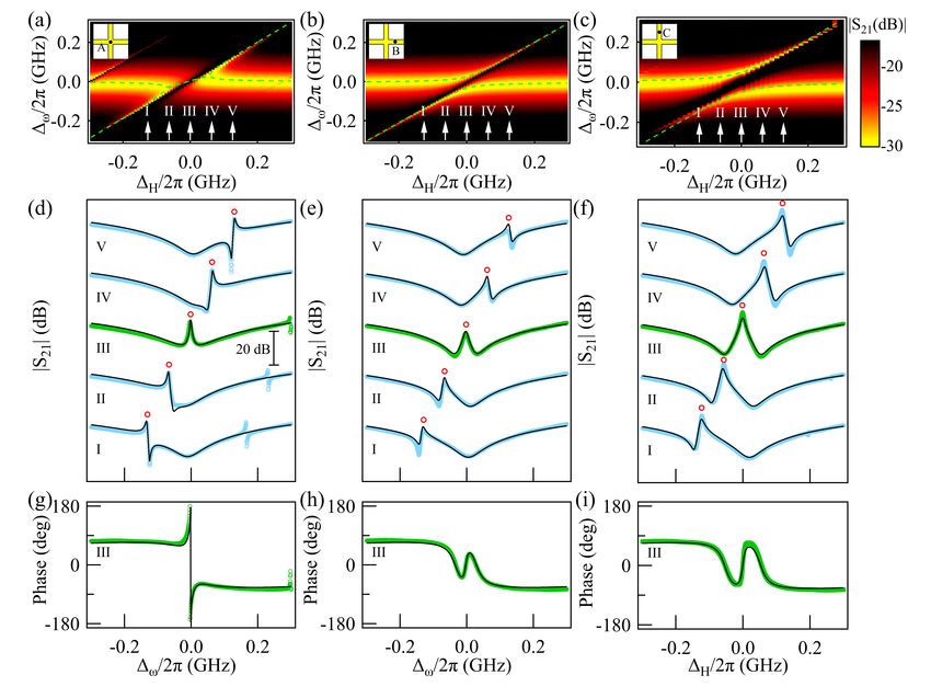
2

                                                                        erties of YIG we can describe the coherent coupling effects
                                                                        due to the resonant permeability through a mutual inductance.
                                                                        In other words, the rf cavity current will produce a magnetic
                                                                        field, which drives magnetization precession and induces a
                                                                        voltage in the cavity circuit. This coupling between the cav-
                                                                        ity current and the YIG is characterized by the mutual induc-
                                                                        tance, which is the ratio between the induced YIG voltage and
                                                                        the time derivative of the varying cavity current[37, 38]. How-
                                                                        ever, there is also an indirect interaction whereby the induced
                                                                        electric field of the YIG sphere will produce an additional cav-
                                                                        ity current due to the finite cavity conductivity. This coupling
                                                                        is related to damping and energy dissipation and may be mod-
                                                                        elled by a mutual resistance[39]. Therefore we choose a com-
                                                                        bination of mutual inductance L1 and mutual resistance R1
                                                                        to describe both the magnetic inductive coupling of level re-
                                                                        pulsion and the resistive coupling of level attraction[33]. The
                                                                        equivalent circuit of the coupled system is shown in Fig. 1 (b).
                                                                           Using the LCR circuit model the transmission spectra of the
                                                                        magnon-photon coupled system can be calculated as,
                                                                                                           iγce
FIG. 1. (a) Picture of the measurement setup with a 1-mm diameter             S21 ∝ 1 −                                    2        (1)
YIG sphere placed a height D = 0.7 mm above the planar microstrip                          ω − ωc + i(γce + γci ) + ω−ωG  m +iγm
cross junction cavity. The two short-terminated vertical arms and two                   √                      √
horizontal arms each have a length of L = 20 mm. The planar cavity      where ωc = 1/ Lc Cc and ωm = 1/ Lm Cm are the reso-
is placed in the x − y plane while an external magnetic field H is      nance frequencies of the cavity and magnon, respectively.
applied in the z direction (perpendicular to the planar cavity). The    γm = Rm /2Lm is the YIG damping while γce and γci are
range of YIG locations is indicated by the 10 mm × 10 mm dashed         the extrinsic and intrinsic cavity damping, see Appendix A
blue box. (b) Equivalent circuit of the coupled system. Circuit el-     for detailed discussion of cavity transmission.   The complex
                                                                                                                √
ements used to model the YIG sphere are highlighted by the green        coupling strength G = (L1 ω + iR1 )/ 4Lc Lm is related to
box while the coupling term is emphasized by a blue box. (c) Cavity     the mutual inductance and resistance. For level repulsion L1
spectra of experimental data (green), theory (black) and CST simu-      is dominant, the coupling strength is real and the hybridized
lation (red, -20 dB offset), with three resonant modes labelled Mode
                                                                        modes are repelled. For level attraction L1 diminishes and
1, Mode 2 and Mode 3.
                                                                        results in an imaginary coupling strength due to R1 . In this
                                                                        case the modes are attracted by the coupling. In order to be
                                                                        consistent with the notation of Ref. 30 we choose an absolute
                                                                                                                   iΦ
                                                                        value of the coupling strength |G| = |ge 2 |. Therefore for
sphere, chosen for its high spin density, low losses and there-         pure level repulsion Φ = 0 and the absolute coupling strength
fore large photon-magnon coupling[34], is mounted on an x-                             √
                                                                        is |g| = L1 ω/ √4Lc Lm , while for pure level attraction Φ = π
y-z stage at a fixed height of D = 0.7 mm from the cavity in            and |g| = R1 / 4Lc Lm .
the z direction. This setup allows us to continuously tune the             An amplitude mapping of the microwave transmission
YIG position in the x-y plane, and hence to change the lo-              spectra S21 , measured using a vector network analyzer with
cal field and the coupling effect. In our experiment the YIG            the YIG in the centre of the cross junction at position A,
sphere (black circle) can be moved within the 10 mm × 10                is shown in Fig. 2 (a) as a function of the frequency
mm range of the dashed blue box shown in Fig. 1 (a). The                and field detunings, ∆ω = ω − ωc and ∆H = ωr (H) − ωc .
cavity transmission spectra S21 (green symbols) is displayed            Here we have used Mode 2 with ωc /2π = 6.253 GHz.
in Fig. 1 (c), where three resonant modes, with frequencies             The uncoupled magnon mode with damping γm /2π = 0.004
of ωc /2π = 3.22, 6.253 and 9.39 GHz, are labelled as Mode              GHz follows the Kittel dispersion ωr (H) = γ(H + HA ),
1, Mode 2 and Mode 3. Black and red curves correspond to                where γ = 2π × 27.4 µ0 GHz/T is the gyromagnetic ratio and
theoretical calculations using Eq. (A.2b) and Computer Sim-             µ0 HA = 2.26 mT is the magneto-crystalline anisotropy field.
ulation Technology (CST) simulations, respectively.                        At position A, a high symmetric point of the structure,
   To couple with the cavity circuit, the YIG sphere acts as            where both the rf e-field and h-field are at a minimum no
a resonant circuit, with self inductance, capacitance and re-           matter which port is input, see Fig. A.2 (c) and (f), we ob-
sistance connected in series and labelled as Lm , Cm , Rm . To          serve level attraction by tuning the FMR frequency around
describe the coupling we consider both direct and indirect in-          ωc . The hybridized frequencies bend towards each other and
teractions between the cavity electromagnetic fields and the            meet at two exceptional points[30, 31]. In the region between
magnetic material. First, the electromagnetic field will be di-         these two points the modes coalesce and the absolute coupling
rectly influenced by the permittivity and permeability, which           strength is |g/2π| = 33 MHz. In order to change the coupling
in general can be modelled by a mutual capacitance and in-              featrue we moved the YIG in the x-y plane to position B and
ductance respectively [29, 35, 36]. Due to the magnetic prop-           C. The field distribution at position B is shown in Fig. A.2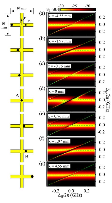
3

FIG. 2. (a) S21 amplitude mapping, (d) S21 amplitude spectra and (g) S21 phase spectra of level attraction when YIG is mounted in position
A. The same for (b), (e) and (h) in position B and (c), (f) and (i) in position C. Amplitude peaks are labelled as red circles in the amplitude
spectra. The green dash lines in the amplitude mappings and black curves in the amplitude and phase spectra are theoretical calculations.

(c) and (f). Although no field is input at Port 2 while measur-           in Fig. 2 (g), corresponding to an amplitude peak between
ing S21 , the vacuum field couples to the magnons and leads               the two attracted modes. In level repulsion the amplitude dip
to magnon-photon Rabi oscillations[40]. As shown in Fig. 2                at each hybridized mode corresponds to two π phase delays,
(b) and (c), level repulsion is observed at position B (x = 1.82          while the peak in between is observed as an opposite π-phase
mm) in the right arm and at position C (y = 1.82 mm) in the               shift at ∆ω = 0 [41, 42], see Fig. 2 (h) and (i). Both tech-
upper arm. In these cases the two hybridized modes are re-                niques are in agreement and confirm the presence of level at-
pelled by each other and open a Rabi-like gap, with a cou-                traction in the transmission spectra of Fig. 2 (d).
pling strength of 32.5 and 54 MHz respectively, determined
                                                                             To examine the transition between level attraction and re-
from the splitting.
                                                                          pulsion we moved the YIG position continuously along the
   In Fig. 2 (d) when the field detuning is set to ∆H = 0,                x axis, between |x| < 5 mm. Selected YIG positions and
the transmission spectra amplitude of level attraction is plot-           the corresponding mappings are shown in Fig. 3, demonstrat-
ted as a function of ∆ω using green circles. A resonance peak             ing the systematic evolution between level repulsion and level
appears at ∆ω = 0. However it looks quite similar to the zero-            attraction about the crossing point (x = 0 mm, y = 0 mm).
detuning spectrum of level repulsion in Fig. 2 (e) and (f). For-          When the |x| position is decreased from |x| = 4.55 mm to
tunately the amplitude peaks in our system, characterized by              |x| = 0.76 mm the inductive coupling is dominant and the
a suppression of |S21 | amplitude originating from the destruc-           mapping shows level repulsion. The Rabi-like gap between
tive interference between the magnon response and driving                 the two hybridized modes increases at first, reaching a maxi-
force[41], can be used to distinguish the two forms of cou-               mum at |x| = 1.97 mm, after which the gap gradually closes,
pling. For the known case of level repulsion, shown in Fig.               reaching a minimum at |x| = 0.76 mm where the two modes
2 (e) and (f), the amplitude peak always appears between the              appear to cross. After |x| = 0.76 mm the system enters a level
coupled modes. However in the case of level attraction the                attraction region, dominated by resistive coupling, and the
peak appears outside of the two hybridized modes.                         coupling strength again increases. At x = 0 mm the strongest
                                                                          level attraction is observed.
   Another robust method to distinguish level attraction and
repulsion is to examine the transmission phase at ∆H = 0. In                 The coupling strength depending on YIG sphere’s x posi-
level attraction a single 2π-phase jump at ∆ω = 0 is observed             tion can be determined for all three modes by using Eq. (1) to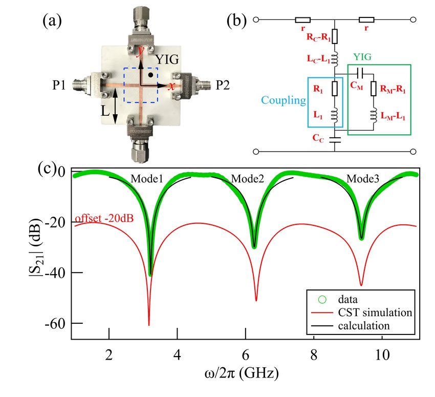
4
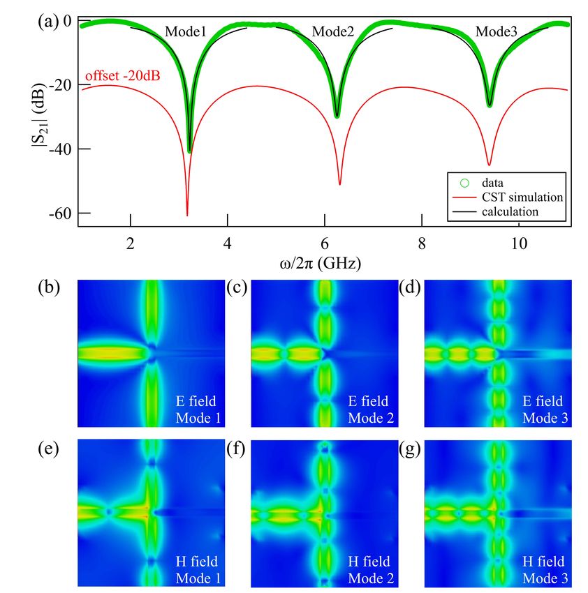
FIG. 4. Evolution of the absolute coupling strength, |g|, for (a)
Mode 1, (b) Mode 2, and (c) Mode 3 when YIG is moved from x =
-5 mm to 5 mm with y = 0 mm. The shaded region indicates level
attraction. LR and LA are abbreviations of level repulsion and level
attraction.
with maximal effect at |x| = 0 due to the indirect interaction
FIG. 3. In the left panel, positions of YIG are given within a 10
between the photon and magnon modes. Consistent with pre-
mm × 10 mm area. Amplitude mappings in the right panel show a vious study using a special Fabry-Perot-like resonator[30], it
systemtic evolution from level repulsion to level attraction and back is clearly seen that two competing magnon-photon coupling
to level repulsion. The green dash lines in amplitude mapping are effects coexist at general experimental conditions in our pla-
theoretical calculations. nar cavity.
III. CONCLUSIONS
fit S21 . The results are summarized in Fig. 4. In the shaded
region the system is dominated by resistive coupling, where In this work we have developed an LCR circuit model to
level attraction is observed. This is in contrast to the region of describe both level repulsion and its transition into level at-
level repulsion dominated by inductive coupling. At |x| = 5 traction, and have experimentally demonstrated the existence
mm a small inductance leads to weak level repulsion. As |x| of mutual resistive coupling induced level attraction in a pla-
decreases the Rabi-like gap gradually opens and the coupling nar cavity. The realization of resistive coupling provides a
strength increases to its maximum value, meaning that the in- new avenue for the development of circuit designs which im-
ductance must increase and the interaction proceeds via the plement the phenomenon of level attraction. By realizing such
magnetic field. After that the mutual inductance begins to de- an on-chip device, future coupling modules may be more eas-
crease and then the mutual resistance R1 emerges and grows ily integrated into a lumped element system.
in near level crossing condition. When the overall coupling Note added. After the paper was written, we found in
strength reaches a minimum, a level crossing appears and the last week a preprint also studying the level attraction ef-
marks the transition. As |x| is decreased further beyond the fect in planar cavity, but with a different cavity design, see
crossing condition towards zero, level attraction is observed, arXiv:1901.01729, 2019.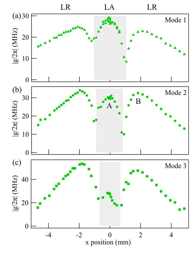
5

                     ACKNOWLEDGMENTS

  This work was funded by NSERC and the China Scholar-
ship Council. We would like to thank M. Harder, I. Proskurin,
R. L. Stamps and T. J. Silva for helpful discussions and sug-
gestions.

       Appendix A: Design and characterization of cavity

FIG. A.1. (a) Design of a Michelson-type microwave interferome-
ter with two short-terminated vertical arms and two horizontal arms.
(b) The ideal topology of the interferometer consists of two series
transmission lines and two short-ended shunt stubs with the same         FIG. A.2. (a) The cavity spectra S21 is shown as green symbols, with
impedance and electrical length. The individual ABCD matrices are        black and red curves corresponding to the theoretical calculation and
given by M1 , M2 , M3 , M4 . (c) Equivalent circuit of the interferom-   CST simulations (-20 dB offset), respectively. The rf electric field
eter.                                                                    distribution of Mode 1, Mode 2 and Mode 3 are shown in (b), (c) and
                                                                         (d) while the rf magnetic field distributions are shown in (e), (f) and
                                                                         (g).
   Inspired by the well known performance of interferomet-
ric techniques, which can operate over a large frequency
range and have excellent signal-to-noise ratio (SNR) in mag-             where
netic resonance experiments[43, 44], we used microstrip cross
junction to fabricate a Michelson-like interferometer. The                                      cos θ jZ0 sin θ
                                                                                   M1 = M4 =                                            (A.1b)
microstrip cross junction topology is depicted in Fig. A.1                                   j Z10 sin θ cos θ
(a). This cross-shaped microstrip is fabricated using two per-
pendicular 1.67 mm-wide transmission lines on a 0.813 mm
thick RO4003C substrate. The two horizontal arms are con-                                                          1        0
                                                                                              M2 = M3 =             1                   (A.1c)
nected to a vector network analyzer (VNA) to enable mi-                                                         jZ0 tan θ   1
crowave transmission measurements while two vertical arms
are short-terminated. Each arm shares the same characteristic              From this ABCD matrix, the transmission parameter can be
impedance Z0 = 50 Ω and electrical length θ = kL. L = 20                 derived as:
mm is the real length of each arm and k = iα + β is the com-                                2          1
plex wave number in a lossy material[45]. Attenuation con-                 S21 =                      = ei2θ (1 − ei2θ ) (A.2a)
                                                                                   A + B/Z0 + CZ0 + D  2
stant is α and phase constant β = ω/υp , υp is the phase ve-
locity at medium.                                                        which results in a resonant dip of the transmission spectra at
   Because the feature dimensions of the cross junction are              ω = ωc .
much smaller than the wavelength of the microwaves em-                     For the near resonant condition αL  1, so
ployed, the scattering properties of our device can be mod-              e−2αL = Γ ≈ 1 is smaller than 1[44].             Furthermore
elled by the cascade matrices M1 , M2 , M3 , M4 shown in Fig.            βc = nπ/L = ωc /υp when n is an integer, so ei2βc L = 1 and
A.1 (b). To compute the ABCD matrix for the whole cavity,                Eq. (A.2a) can be rewritten as:
we can simply multiply the matrices of the individual two-port
                                                                                        1                iγce
element[44]:                                                                    S21 ≈       1−                                  (A.2b)
                                                                                        2       ω − ωc + i(γce + γci )
                                                                                          υ                            υ

       A B
                                                                        where γce = Γ 2Lp and γci = (1 − Γ) 2Lp are the extrinsic and
                 = M1 M2 M3 M4                                           intrinsic damping of the cavity.
       C D
                                                            (A.1a)        Fig. A.1 (c) shows the equivalent phenomenological LCR
                     2 cos (2θ) + 1 2jZ0 sin (2θ)                        circuit model which quantitatively describes the resonant be-
                 =
                     −2j cos(2θ)
                              Z0
                                 cot θ
                                       2 cos (2θ) + 1                    haviour. The circuit consists of lumped elements of resistance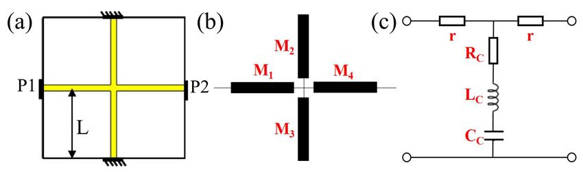
6

                                                                                                  1
                                                                         Zc = Rc + jωLc + jωC         = jZ0 tan θ/(2 cos(2θ))       which
TABLE A.1. Resonance frequency, ωc , extrinsic damping, γce , and                                   c                            √
intrinsic damping, γci , of Mode 1, Mode 2 and Mode 3.                   describes the cavity resonance. Defining ωc = 1/ Lc Cc ,
                                                                         γce = (Z0 + r)/4Lc and γci = Rc /2Lc , the transmission
                                                                         equation derived from the circuit model is the same as
                    Mode 1           Mode 2           Mode 3             Eq. (A.2b). We note that γci  γce since 1 − Γ  Γ and
      ωc /2π       3.22 GHz         6.253 GHz        9.39 GHz            Rc  21 (Z0 + r).
                                                                            The performance of this Michelson-type microwave inter-
     γce /2π       0.99 GHz         0.99 GHz         0.99 GHz
                                                                         ferometer was first characterized using a VNA measurement;
     γci /2π       0.010 GHz        0.034 GHz       0.052 GHz            see the green circles in Fig. A.2 (a). The three resonant modes
                                                                         are labelled Mode 1, Mode 2 and Mode 3. Using Eq. (A.2b)
                                                                         (black curves) the resonant features can be calculated, with
                                                                         the resonant frequency ωc , extrinsic damping γce and intrin-
r, Rc , inductance Lc and capacitance Cc . The matrix of this            sic damping γci determined based on a fit to the experimental
circuit is:                                                              data of Fig. A.2 (a) and summarized in Table A. As expected
             "       # "                        #                        all modes share the same extrinsic damping while the intrin-
               A B          1 + Zrc r(2 + Zrc )                          sic damping increases with resonant frequency, which may be
                       =       1
                                                       (A.3)
               C D            Zc      1 + Zrc                            due to interference effects. The resonant features are also re-
                                                                         produced by CST, and are plotted as the red curve with a -20
This lumped circuit ABCD matrix must correspond                          dB offset. To clearly see the interference pattern, the rf e-field
to Eq.     (A.1a) which allows us to identify the two                    and h-field distribution, as modelled by CST, is shown in Fig.
small symmetric resistances r = jZ0 tan θ  Z0 which                     A.2 (b) - (g), in which colour variance reflects the absolute
contribute the extrinsic losses and a shunt impedance                    electric or magnetic field strength.

 [1] G. Khitrova, H. Gibbs, F. Jahnke, M. Kira, and S. Koch, Nonlin-     [12] S. Gröblacher, K. Hammerer, M. R. Vanner, and M. As-
     ear optics of normal-mode-coupling semiconductor microcavi-              pelmeyer, Observation of strong coupling between a microme-
     ties, Reviews of Modern Physics 71, 1591 (1999).                         chanical resonator and an optical cavity field, Nature 460, 724
 [2] J.-M. Raimond, M. Brune, and S. Haroche, Manipulating quan-              (2009).
     tum entanglement with atoms and photons in a cavity, Reviews        [13] Ö. O. Soykal and M. Flatté, Strong field interactions between
     of Modern Physics 73, 565 (2001).                                        a nanomagnet and a photonic cavity, Physical Review Letters
 [3] Z.-L. Xiang, S. Ashhab, J. You, and F. Nori, Hybrid quantum              104, 077202 (2010).
     circuits: Superconducting circuits interacting with other quan-     [14] H. Huebl, C. W. Zollitsch, J. Lotze, F. Hocke, M. Greifenstein,
     tum systems, Reviews of Modern Physics 85, 623 (2013).                   A. Marx, R. Gross, and S. T. Goennenwein, High cooperativ-
 [4] M. Aspelmeyer, T. J. Kippenberg, and F. Marquardt, Cavity op-            ity in coupled microwave resonator ferrimagnetic insulator hy-
     tomechanics, Reviews of Modern Physics 86, 1391 (2014).                  brids, Physical Review Letters 111, 127003 (2013).
 [5] C.-M. Hu, Dawn of cavity spintronics, Physics in Canada, 72,        [15] Y. Tabuchi, S. Ishino, T. Ishikawa, R. Yamazaki, K. Usami,
     76 (2016).                                                               and Y. Nakamura, Hybridizing ferromagnetic magnons and mi-
 [6] M. Harder and C.-M. Hu, Chapter Two - Cavity Spintron-                   crowave photons in the quantum limit, Physical Review Letters
     ics: An Early Review of Recent Progress in the Study of                  113, 083603 (2014).
     Magnon?Photon Level Repulsion, in Solid State Physics, Vol.         [16] L. Bai, M. Harder, Y. Chen, X. Fan, J. Xiao, and C.-M. Hu,
     69, edited by R. E. Camley and R. L. Stamps (Academic Press,             Spin pumping in electrodynamically coupled magnon-photon
     Cambridge, 2018) pp. 47 – 121.                                           systems, Physical Review Letters 114, 227201 (2015).
 [7] S. Sharma, Y. M. Blanter, and G. E. W. Bauer, Optical cooling       [17] M. Goryachev, W. G. Farr, D. L. Creedon, Y. Fan, M. Kostylev,
     of magnons, Physical Review Letters 121 087205 (2018).                   and M. E. Tobar, High-cooperativity cavity QED with magnons
 [8] G. Khitrova, H. Gibbs, M. Kira, S. W. Koch, and A. Scherer,              at microwave frequencies, Physical Review Applied 2, 54002
     Vacuum Rabi splitting in semiconductors, Nature Physics 2, 81            (2014).
     (2006).                                                             [18] N. Kostylev, M. Goryachev, and M. E. Tobar, Superstrong cou-
 [9] A. Wallraff, D. I. Schuster, A. Blais, L. Frunzio, R.-S. Huang,          pling of a microwave cavity to yttrium iron garnet magnons,
     J. Majer, S. Kumar, S. M. Girvin, and R. J. Schoelkopf, Strong           Applied Physics Letters 108, 062402 (2016).
     coupling of a single photon to a superconducting qubit using        [19] X. Zhang, C.-L. Zou, L. Jiang, and H. X. Tang, Strongly cou-
     circuit quantum electrodynamics, Nature 431, 162 (2004).                 pled magnons and cavity microwave photons, Physical Review
[10] J. Majer, J. Chow, J. Gambetta, J. Koch, B. Johnson, J. Schreier,        Letters 113, 156401 (2014).
     L. Frunzio, D. Schuster, A. Houck, A. Wallraff, A. Blais, M.        [20] X. Zhang, C.-L. Zou, N. Zhu, F. Marquardt, L. Jiang, and H. X.
     Devoret, S. Girvin, and R. Schoelkopf, Coupling superconduct-            Tang, Magnon dark modes and gradient memory, Nature Com-
     ing qubits via a cavity bus, Nature 449, 443 (2007).                     munications 6, 8914 (2015).
[11] K. Hennessy, A. Badolato, M. Winger, D. Gerace, M. Atatüre,        [21] Y. Tabuchi, S. Ishino, A. Noguchi, T. Ishikawa, R. Yamazaki,
     S. Gulde, S. Fält, E. L. Hu, and A. Imamoğlu, Quantum nature           K. Usami, and Y. Nakamura, Coherent coupling between a fer-
     of a strongly coupled single quantum dot–cavity system, Nature           romagnetic magnon and a superconducting qubit, Science 349,
     445, 896 (2007).                                                         405 (2015).
7
[22] H. Maier-Flaig, M. Harder, R. Gross, H. Huebl, and S. T. Goen- tum systems embedded in a continuum, Physics Reports 374,
nenwein, Spin pumping in strongly coupled magnon-photon 271 (2003).
systems, Physical Review B 94, 054433 (2016). [33] A. B. Pippard, The Physics of Vibration (Cambridge University
[23] B. Yao, Y. S. Gui, J. W. Rao, S. Kaur, X. S. Chen, W. Lu, Y. Press, Cambridge, 2007).
Xiao, H. Guo, K.-P. Marzlin, and C.-M. Hu, Cooperative po- [34] A. Serga, A. Chumak, and B. Hillebrands, YIG magnonics,
lariton dynamics in feedbackcoupled cavities, Nature Commu- Journal of Physics D: Applied Physics 43, 264002 (2010).
nications 8, 1437 (2017). [35] W. Barry, A broad-band, automated, stripline technique for the
[24] J.-M. Pirkkalainen, S. Cho, J. Li, G. Paraoanu, P. Hakonen, and simultaneous measurement of complex permittivity and per-
M. Sillanpää, Hybrid circuit cavity quantum electrodynamics meability, IEEE Transactions on Microwave Theory and Tech-
with a micromechanical resonator, Nature 494, 211 (2013). niques 34, 80 (1986).
[25] M. Delbecq, V. Schmitt, F. Parmentier, N. Roch, J. Viennot, G. [36] J.-S. G. Hong and M. J. Lancaster, Microstrip Filters for RF/
Féve, B. Huard, C. Mora, A. Cottet, and T. Kontos, Coupling Microwave Applications, Vol 167 (John Wiley & Sons, New
a quantum dot, fermionic leads, and a microwave cavity on a York, 2004)
chip, Physical Review Letters 107, 256804 (2011). [37] F. W. Grover, Inductance Calculations: Working Formulas and
[26] V. Singh, S. Bosman, B. Schneider, Y. M. Blanter, A. Tables (Courier Corporation, Mineola, 2004).
Castellanos-Gomez, and G. Steele, Optomechanical coupling [38] A. Zangwill, Modern electrodynamics (Cambridge University
between a multilayer graphene mechanical resonator and a su- Press, Cambridge, 2013).
perconducting microwave cavity, Nature Nanotechnology 9, [39] W. G. Hurley and M. C. Duffy, Calculation of self and mutual
820 (2014). impedances in planar magnetic structures, IEEE Transactions
[27] I. Chiorescu, Y. Nakamura, C. Harmans, and J. Mooij, Coher- on Magnetics 31, 2416 (1995).
ent quantum dynamics of a superconducting flux qubit, Science [40] G. S. Agarwal, Quantum Optics (Cambridge University Press,
299, 1869 (2003). Cambridge, 2012).
[28] A. A. Abdumalikov Jr, O. Astafiev, Y. Nakamura, Y. A. [41] M. Harder, P. Hyde, L. Bai, C. Match, and C.-M. Hu, Spin dy-
Pashkin, and J. Tsai, Vacuum Rabi splitting due to strong cou- namical phase and antiresonance in a strongly coupled magnon-
pling of a flux qubit and a coplanar-waveguide resonator, Phys- photon system, Physical Review B 94, 054403 (2016).
ical Review B 78, 180502 (2008). [42] C. Sames, H. Chibani, C. Hamsen, P. A. Altin, T. Wilk, and G.
[29] S. Kaur, B. Yao, Y.-S. Gui, and C.-M. Hu, On-chip artifi- Rempe, Antiresonance phase shift in strongly coupled cavity
cial magnon-polariton device for voltage control of electromag- QED, Physical Review Letters 112, 043601 (2014).
netically induced transparency, Journal of Physics D: Applied [43] I. S. Krishna, R. K. Barik, and S. Karthikeyan, A dual-band
Physics 49, 475103 (2016). crossover using cross-shaped microstrip line for small and large
[30] M. Harder, Y. Yang, B. Yao, C. Yu, J. Rao, Y. Gui, R. Stamps, band ratios, International Journal of Microwave and Wireless
and C.-M. Hu, Level attraction due to dissipative magnon- Technologies 9, 1629 (2017).
photon coupling, Physical Review Letters 121, 137203 (2018). [44] E. R. Edwards, A. B. Kos, M. Weiler, and T. J. Silva, A mi-
[31] N. Bernier, L. Tóth, A. Feofanov, and T. Kippenberg, Level crowave interferometer of the Michelson-type to improve the
attraction in a microwave optomechanical circuit, Physical Re- dynamic range of broadband ferromagnetic resonance measure-
view A 98, 023841 (2018). ments, IEEE Magnetics Letters 8, 1 (2017).
[32] J. Okolowicz, M. Ploszajczak, and I. Rotter, Dynamics of quan- [45] D. M. Pozar, Microwave Engineering (John Wiley & Sons, New
York, 2009).You can also read