Cryogenic sequenced layering for the 3D reconstruction of biological objects - Nature
←
→
Page content transcription
If your browser does not render page correctly, please read the page content below
www.nature.com/scientificreports
OPEN Cryogenic sequenced layering
for the 3D reconstruction
of biological objects
Vladimir Nikolaevich Nikolenko2,4*, Alexey Anatolyevich Terpilovsky1,
Alexey Leonidovich Kuzmin2, Regina Alekseevna Lukashkina1,
Alexey Evgenievich Strizhkov2, Andrei Vladimirovich Suslov2,
Ekaterina Vladimirovna Kochurova3, Liliya Vladimirovna Gavrushova2 &
Mikhail Yegorovich Sinelnikov5*
Three-dimensional (3D) visualization is applied throughout many specialities, prompting an important
breakthrough in accessibility and modeling of data. Experimental rendering and computerized
reconstruction of objects has influenced many scientific achievements, facilitating one of the greatest
advancements in medical education since the first illustrated anatomy book changed specialist
training forever. Modern medicine relies on detailed, high quality virtual models for educational,
experimental and clinical purposes. Almost all current virtual visualization methods rely on object
slicing producing serial sections, which can then be digitalized or analyzed manually. The tendency
to computerize serial sections roots from convenience, accessibility, decent visualization quality and
automation capabilities. Drawbacks of serial section imaging is tissue damage occurring within each
consequent sectioning. To utilize the important aspects of real-life object reconstruction, and maintain
integrity of biological structures, we suggest a novel method of low-temperature layering of objects
for digitization and computerized virtual reconstruction. Here we show the process of consequent
imaging of each novel layer of a biological object, which provides a computer with high quality data for
virtual reconstruction and creation of a multidimensional real-life model. Our method prevents tissue
deformation and biodegradation due to specific methods used in preparation of the biological object.
The resulting images can be applied in surgical training, medical education and numerous scientific
fields for realistic reconstruction of biological objects.
Three-dimensional reconstruction of objects is a necessary technology in furthering scientific progress. In health
sciences, 3D technology presents opportunity for improved surgical training, diagnostic modeling, cancer stud-
ies, and is applied in biochemistry, regenerative medicine, reconstructive surgery and other numerous fields1–9.
Current methods of morphological analysis require fixation, embedding, sectioning, after which the acquired
samples can be analyzed10–15. Sectioning is most commonly performed via microtome slicing, producing 5–20 μm
thick slices. This method of microtome slicing includes mechanical separation of fixed and embedded biological
tissues and prior chemical exposition, which often leads to damage and disfigurement of biological material. The
preservation of biological tissue integrity and achievement of quality computerized visualization is necessary
for future use of acquired images in studies and experimental modeling, which have a variety of applications.
Technology of three-dimensional reconstruction of biological objects has been in development for the
past 25–30 years. Premier projects with multidimensional reconstruction included the Visible Human and the
VOXEL-MAN projects. Visible Human developed a digitized sequence of 1871 cross-sections of a male human
body with a step of 1 mm, and 5,000 cross-sections of a female human body (0.33 mm step)16. VOXEL-MAN
used data from the Visible Human project to develop a 3D educational software17. An article published by authors
1
Laboratory of Virtual Biology, village Red Pakhra, Rodnikovaya Street, 2, Moscow, Russia 108828. 2Department
of Human Anatomy, Sechenov University, Mohovaya, 11/10, Moscow, Russia 125009. 3Department of Orthopedic
Dentistry, Sechenov University, Tubetskaya, 8, Moscow, Russia 119048. 4Department of Anatomy, Lomonosov
Moscow State University, GSP‑1, Leninskie Gory, Moscow, Russia 119991. 5Institute for Regenerative Medicine,
Sechenov University, Tubetskaya, 8, Moscow, Russia 119048. *email: vn.nikolenko@yandex.ru; sinelnikov_m_e@
staff.sechenov.ru
Scientific Reports | (2020) 10:11899 | https://doi.org/10.1038/s41598-020-68682-z 1
Vol.:(0123456789)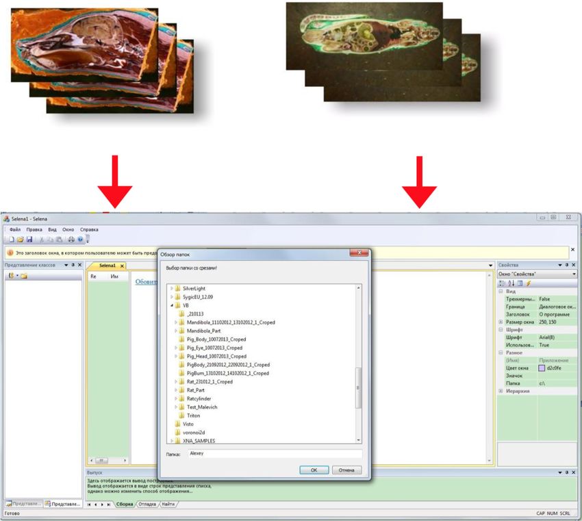
www.nature.com/scientificreports/
Figure 1. Layered reconstruction of a sectioned corn pellet. Visualized embedded in paraffin [(a) axonometric
reconstruction; (b) diagonal cut of digitized pellet; (c) transverse cut of digitized pellet; (d) longitudinal cut of
digitized pellet].
Sieber et al. discusses a method of temporal bone modeling using a method of micro-slicing with digitization.
The authors claim several procedural inaccuracies due to chemical dehydration, geometric deformations due to
sequential grinding and micro-slicing, stitching instability18. In order to exclude possible inaccuracies, cryogenic
preparation and high quality milling should be carried out. A complete and more accurate rendering can be
achieved by consequent removal of layers from a specimen with digitization of each novel surface.
Our personal experience with layered reconstruction using series of sections was carried out on small bio-
logical samples, including a corn pellet, spruce seed and a rainbow fish. The corn pellet can be seen in primary
multidimensional reconstruction with moulding material still in place (Fig. 1). Computerized removal of molding
material provides better visualization and multidimensional modeling (Figs. 2, 3). Our attempts with virtual 3D
reconstruction of microtome sectioned material showed significant drawbacks of this method, due to notable
tissue deformation and abundance of artifacts. This was due to the fact that each layer was deformed during
preparation of sections, making impossible proper image layering. Consequentially, we began development of
a method that would account for these deficiencies.
Modern biological object imaging in different specialties requires precise, high-quality and multidimensional
capabilities. Special interest to layered object visualization is regarded in medical pathology. Histological and
microscopic imaging highly depends on mechanical sectioning, which is often performed with a significant
interval between layers to minimize tissue deformation. Three-dimensional visualization with a low interval
between layers and minimal tissue deformation is required for correction of technical inaccuracies. Layered,
multidimensional, computerized imaging with minimal structural damage is the next step in object visualization
technology, which can facilitate a new age of scientific discovery.
Scientific Reports | (2020) 10:11899 | https://doi.org/10.1038/s41598-020-68682-z 2
Vol:.(1234567890)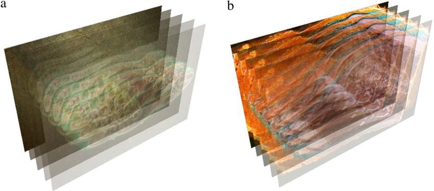
www.nature.com/scientificreports/

                            Figure 2.  Layered reconstruction of a sectioned spruce seed. Three-dimensional reconstruction with removed
                            molding material. Layering step 10 μm.

                            Results
                            We developed a novel method of virtual reconstruction of biological objects by sequenced layering via high-

                            Figure 3.  Layered reconstruction of sectioned rainbow fish. Paraffin removed. 10 μm step.

                            precision low temperature micro-milling of flash-frozen embedded specimen and consequent digitization.
                            Flash-freezing of biological material allows for the elimination of the need for chemical preparation, which is
                            performed in classical methods of fixation for tissue dehydration, and is known to cause structural damage. The
                            proposed method accounts for different physical and chemical attributes of biological objects, preserving the
                            entire specimen in exact conditions upon cryogenic conservation. Digitization and computerized rendering with
                            multidimensional modeling are performed using successive surface layer images. After complete micro-milling
                            of entire cryogenic specimen, a three-dimensional model consisting of discrete high quality layered elements is
                            attained using captured surface images from each novel layer. The layer step is minimal due to specific cryogenic
                            micro-milling technology allowing for a step of as little as 2 μm.
                                A low-temperature face micro-milling construction was built for this project, the structure of the negative-
                            temperature milling device includes a cryogenic chamber for the fixation of the biological object, a face micro-
                            milling installment for repeated interaction with the specimen, a digitization device and lighting sources (Fig. 4,
                            5).
                                The result of the developed virtual reconstruction device is a series of discrete digital elements (layers),
                            acquired from the surface of a flash-frozen embedded biological object in the cryogenic chamber with step-by-
                            step consecutive micro-milling and digitization of novel layers. The superior feature of this device is elimina-
                            tion of object slicing, therefore the characteristic integrity of the biological tissues is maintained, preventing
                            tissue deformation of different sorts. The process of flash-freezing of the biological object with consequent
                            low-temperature embedding and secondary flash-freezing of the embedded biological object provides overall
                            tissue stability during precision layered micro-milling in negative-temperatures.

Scientific Reports |   (2020) 10:11899 |               https://doi.org/10.1038/s41598-020-68682-z                                            3

                                                                                                                                        Vol.:(0123456789)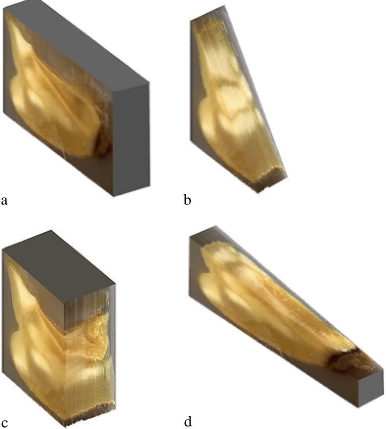
www.nature.com/scientificreports/

                                      Figure 4.  General view of device for virtual reconstruction of biological objects; anterior view (1—anti-
                                      vibration base; 2—object fixation device; 3—face micro-milling structure; 4—cryogenic chamber for flash-
                                      frozen object; 5—primary table; 6—face micro-mill; 7—spindle mount; 8—electric motor (outside cryogenic
                                      chamber); 9—stability pallet; 10—frozen and embedded biological object; 11—longitudinal linear movement
                                      mechanism; 12—secondary table mount; 13—transverse linear movement mechanism; 14—anterior cryogenic
                                      chamber wall; 15—digitization window management structure; 16—window transition unit; 17—damper; 18—
                                      cryogenic chamber cover; 19—flexible minimally resistant cable.

                                      Figure 5.  Posterior view of device for virtual reconstruction of biological objects (1—anti-vibration base;
                                      3—face micro-milling structure; 4—cryogenic chamber for flash-frozen object; 15—digitization window
                                      management structure; 18—cryogenic chamber cover; 20—digital camera; 21—digitization window; 22—
                                      posterior cryogenic chamber wall; 23—lighting fixtures; 24—supporting structure for digitization device and
                                      lighting sources; 25—compressor (not shown) access to cryogenic chamber; A–A—digitization window closure
                                      line.

          Scientific Reports |   (2020) 10:11899 |             https://doi.org/10.1038/s41598-020-68682-z                                            4

Vol:.(1234567890)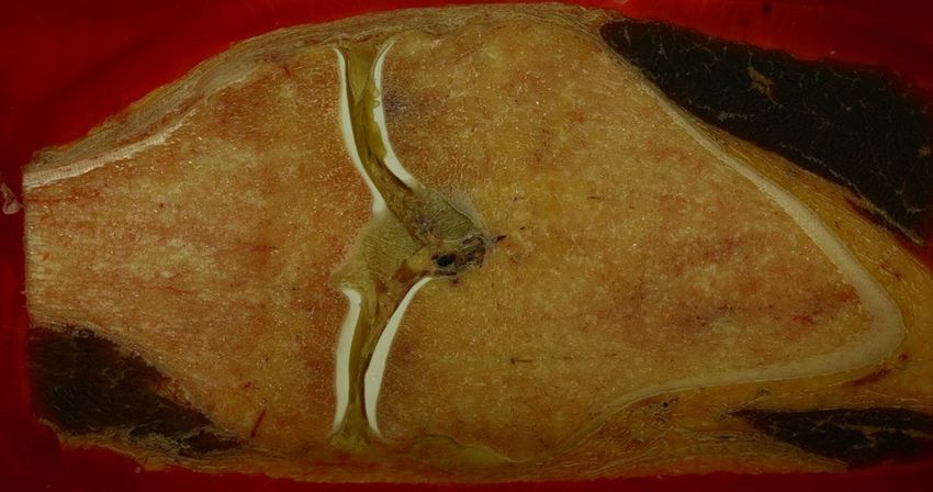
www.nature.com/scientificreports/

                            Figure 6.  Transverse sections of laboratory rat, frozen, fixed, embedded, milled.

                                The developed method for virtual reconstruction of biological objects was applied in several trial cases. In
                            each case, the biological object was flash-frozen using liquid nitrogen at − 196 °C in the cryogenic chamber. No
                            additional chemical preparation of the biological object is required prior to freezing. No staining is required.
                            Upon freezing, the biological object was embedded with a cryogenic medium—Richard-Allan Scientific Neg-50
                            Frozen Section Medium was used. The embedded object was then frozen along with the medium using rapid
                            liquid nitrogen freezing. The dual freezing algorithm was used for retention of native tissue geometry and color
                            characteristics throughout preparation. The formed frozen complex was maintained at a temperature below
                            − 30 °C and humidity of 25–30% in the cryogenic chamber. These parameters allow for tissue integrity stability
                            and proper layering and digitization quality.
                                The developed technique allows for individualized adjustment of parameters, such as freezing temperature,
                            method of embedding, cryogenic chamber environment, milling rate and layering step, as well as digitization
                            modification. The layering step plays an important role in the final 3D rendering. A lower step rate accounts for
                            a lesser rate of inconsistency between layers, and minimizes the occurrence of deformations needing adjust-
                            ment. The camera used for large-scale digital rendering can be exchanged for a microphotography camera for
                            microscopic visualization. A camera upgrade does not require any change to the digitization process, as both the
                            cryogenic milling device and the computer rendering software independently function irregardless of image cap-
                            turing appliance. Devitalization prior to flash-freezing can be performed with formaldehyde vapors if necessary.
                                High quality imaging with a 5–20 μm step rate was tested on laboratory rats. As a result a detailed rendering
                            was reconstructed. The quality of the surface images were exceptional, the surface of the milled and polished
                            material proved to be without notable deficiencies (Fig. 6). High quality digitization of human tissue was also
                            performed (Fig. 7), in both cases the surface texture of the embedded object was smooth and no tissue deforma-
                            tion was noted. An experimental three-dimensional reconstruction of a beetle surprised us with present eggs,
                            which were completely preserved throughout virtual reconstruction. Chitin did not require staining for proper
                            visualization (Fig. 8).
                                Computerized rendering of the acquired images was performed by layered sequencing and digital model
                            reconstruction. Modifiable parameters such as lighting, image resolution, zoom and quality, milling step and
                            color parameters—all influence the process of model digitization. The process of virtual reconstruction com-
                            mences with image capturing. A swine head and an adult rat were used as subjects for this process. Upon flash-
                            freezing, embedding and secondary freezing, the models were placed in the cryogenic chamber of the negative
                            temperature micro-milling device for digitization (Fig. 9).
                                In the cryogenic chamber, at working temperature (maintained at and below − 30 °C) and humidity (25–30%),
                            the experimental subjects underwent sequenced micro-milling. After each step, a photo of the model surface
                            was captured. Therefore the polished via micro-milling surface is captured, the removed layer is discarded. This
                            provides highest tissue integrity and morphological quality. As a result a series of images was captured (Fig. 10).
                                Overall 4,523 layers (each 4,368 × 2,912 pixels) were acquired from the adult rat (step of 10 μm), 5,358 layers
                            (each 4,368 × 2,912 pixels) from the swine head (step of 20 μm). Computerized rendering is performed through
                            Selena software, Version 8.0 (Fig. 11).
                                The acquired models undergo required modification and can be forwarded for further production in more
                            sophisticated software, such as TRIO or VBIO. Essentially, data analysis depends on researcher preference. As
                            an example, an internet platform VBIO is developed with MODEX computing core for three-dimensional slic-
                            ing of the model (Fig. 12).

Scientific Reports |   (2020) 10:11899 |               https://doi.org/10.1038/s41598-020-68682-z                                            5

                                                                                                                                        Vol.:(0123456789)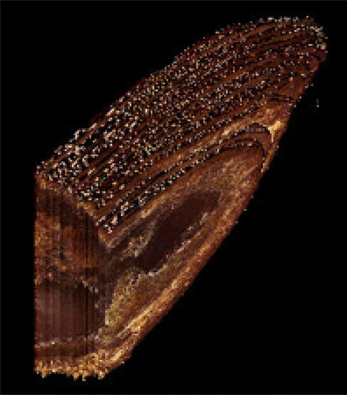
www.nature.com/scientificreports/

                                      Figure 7.  Cross section of a knee joint, digitization image for computer rendering. Normal anatomical
                                      structures are intact, no deformation is seen.

                                         Comparison to classical methods of histological staining through RGB-profiling, evaluation of optic density
                                      and surface profiling was performed. A total of 1,200–2,400 images (1,500 × 1,250 pixels) were generated in .tiff
                                      format for each of the 12 rat knee cartilages. Main morphometric results of both methods can be seen in Table 1.

                                      Figure 8.  Beetle surface image after micro-milling. Notice intact eggs and chitin structure.

                                           *Statistically significant findings.
                                           Increased radial thickness of cartilage in the novel method is characteristic of decreased tissue deformation.
                                      The similarity in cartilage surface factor results indicates diagnostic integrity of the material in both methods.
                                           The developed method of three-dimensional reconstruction of biological objects proved to be successful.
                                      Several dozen models were reconstructed using this method. In each case the images were analyzed for tissue
                                      deformation and integrity of biological structures by a pathologist. No significant deficiencies were found. Over-
                                      all, this method of extracting data from the surface of a prepared cryogenic model provides greater morphological
                                      integrity than computerized layering of separate sections.

                                      Discussion
                                      Evolution of three-dimensional technology has persistently influenced medical research. 3D printing, modeling
                                      of surgical procedures, training, diagnostic procedures, cancer studies all utilize the capabilities of multidimen-
                                      sional reproduction of biological tissues. Our method of virtual reconstruction of biological objects via comput-
                                      erized rendering of a series of surface images from a cryogenic model is dedicated to perfecting the technology
                                      of layering of digitized micro-slices. Instead of digitizing separate histological sections, we captured the surface
                                      of the model after each polish with a micro-mill. The resulting series of surface images are analyzed by special
                                      software and consequent object rendering and reconstruction is performed. Though we used Selena software for
                                      our models, the choice of software depends on researcher preference and availability.
                                          Our method significantly differs from existing methods of optic sectioning microscopy and other tissue
                                      integrity preserving methods of 3D reconstruction of biological objects. This is mainly due to the methods of
                                      sample preparation and sectioning technology. Most classic methods of optic microscopy are based on detection
                                      of scattered light from the evaluated object. Scanning optic microscopy allows for multidimensional scanning,
                                      which provides the ability to reconstruct bitmap surface images of exceptionally high quality. As a result, three
                                      dimensional textures of sample surfaces can be visualized. Scanning probe microscopy specializes in acquiring

          Scientific Reports |   (2020) 10:11899 |               https://doi.org/10.1038/s41598-020-68682-z                                             6

Vol:.(1234567890)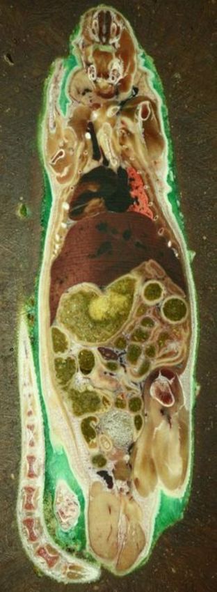
www.nature.com/scientificreports/
Figure 9. Schematic interpretation of digitization process. Frozen embedded biological objects are placed into
the cryogenic chamber of the micro-milling device, where they undergo layered digitization.
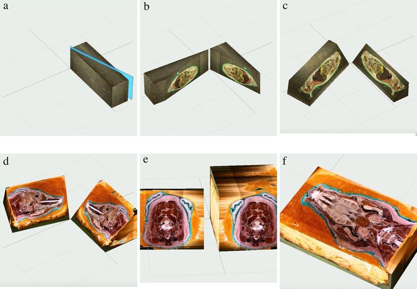
Figure 10. Model of layered image sequence [(a)—adult rat; (b) swine head] (Selena software v.8.0. https://
vbiol.ru).
surface images with regard to local characteristics, and as a result provide significant data on the topographic
textural aspects of the examined sample. Our method specializes in acquiring layered information from a mul-
titexture surface, the geometry of which is close to that of a plane. Therefore, the optic (bitmap) qualities of
each separate layer on the surface of the frozen biological sample are captured and processed. Each layer of the
frozen intact biological sample undergo high precision milling, uncovering an intact lower layer. The surface
area for layered reconstruction is significantly larger than in all other described visualization methods. The
resulting surface images makeup an archive of images, which can be layered and analyzed according to research
specifications. The layered images of milled surfaces then undergo 3D rendering, providing an intricately com-
plete virtual reconstruction of the biological sample in all and with the ability for computerized sectioning and
histological evaluation.
Confocal laser scanning microscopy allows for visualization of cellular structure, yet the depth and area
of optic manipulations is greatly limited by a number of parameters (including wave length and sample optic
properties. Our methods improves on this by offering visualization of morphological and topographical surface
properties not only on the cellular level, but within the range of the intact biological object per layer. Our method
allows for application of fluorescent and radiological examination of samples, since the technology behind the
method does not limit their applicability, as they can be applied prior to cryogenic processing. Apart from a
Scientific Reports | (2020) 10:11899 | https://doi.org/10.1038/s41598-020-68682-z 7
Vol.:(0123456789)
www.nature.com/scientificreports/
Figure 11. Selena software (v.8.0) for image processing and model rendering (https://vbiol.ru).
significantly larger capability for tissue sectioning, which offers the ability to work with intact biological samples,
our method can be applied in reconstruction of a high variety of materials, including titanium implants, medical
instruments and implants, offering the ability to capture the state of interaction between tissue and foreign object.
In a study by Roy et al.19, the authors discuss a method of obtaining thin sections by a cryomicrotome, studied
using light and fluorescence microscopy. The disadvantage of this method is the inevitable deformation of the
material in the preparation of slices, which requires thawing of slices, moving them to a microscope for study
and photographing, the high thickness of slices (5 mm) and inability to evaluate hard structural components
(such as titanium implants. With our method, the study is carried out directly on the cryoblock manufactured
at the beginning of the study, which located in the cryochamber throughout the study. With high-precision
milling, a thin layer of material is removed from the front surface of the cryoblock, therfore(no cut is made. The
raster image is fixed from the new cryoblock surface formed as a result of milling. This eliminates significant
deformation of the material and significantly increases the accuracy of the study. The technological features of
the cryogenic milling device allow for slicing through hardened materials integrated in the biological tissue, such
as titanium implants, chitin, dental implants, metals.
Parrif G. J. conducted a study on the working surface of a cryoblock with dimensions of 30 × 30 μm20. Most of
the anatomical structures of animals and humans are much larger, therefore we created a working cryochamber
surface of 100 × 100 × 100 mm, increasing the surface of each layer by over 1 07. Olivier Salvado et al. developed a
method of 3D cryo-section imaging of blood vesssels lesions for validation of MRI data. Their method involves
classic histological sectioning of soft tissues for immunofluorescent microscopy. The main drawback of this
method is size of layered sections, the use of histological stains and fixators, and inability to slice high density
materials, such as metals. Our method improves on these limitations by expanding the surface of each layer,
Scientific Reports | (2020) 10:11899 | https://doi.org/10.1038/s41598-020-68682-z 8
Vol:.(1234567890)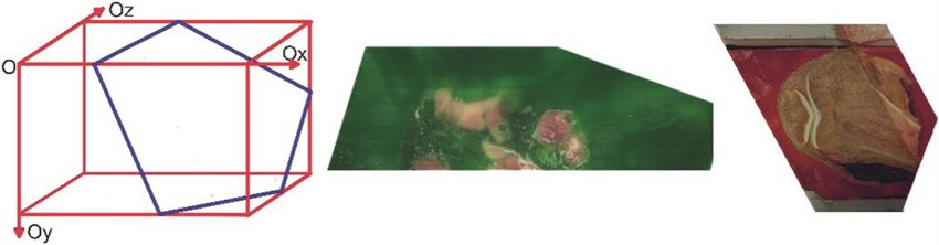
www.nature.com/scientificreports/
Figure 12. Model slicing in third party software (VBIO laboratory software (Selena software v.8.0. https://vbiol
.ru) [(a–c) examples of adult rat model slicing; (d–f) examples of swine head model slicing].
Criterion Classical histological slicing Cryogenic sequenced layering p value
Radial thickness of cartilage, mkm 185 ± 15 232 ± 15 0.032*
Cartilage surface factor 1.08 ± 0.8 1.16 ± 0.5 0.942
Table 1. Morphometric comparison of rat knee cartilage features using two different methods of preperation.
decreasing the step between each surface image (to under 5 μm and developing a high-precision milling device,
capable of slicing through high density materials, therefore significantly expanding the possibility for research
application.
Overall this method improves on existing methods of virtual reconstruction of a series of images, but still
several drawbacks are recognized. Maintenance of cryogenic temperatures throughout the procedure of virtual
reconstruction requires high energy expenditure. Transportation of the model is limited due to the need to
maintain a stable low temperature for purity of results. The developed low temperature face micro-milling device
requires regular maintenance. The presence of mechanical disturbance (operator influence, external vibrations)
can influence the precision of micro-milling, therefore the proposed method should be carried out in a protected
environment. A temperature increase during milling can be seen and should be accounted for by lowering the
temperature in the cryogenic chamber prior to milling. Minor inaccuracies due to accidental camera movement
can cause stitching inaccuracy and should be accounted for. Computerized extraction of the embedding material
requires perfection, the outline of specimens is not always properly identified, which can cause image artifacts.
The cryogenic chamber parameters are currently 200 × 100 × 100 mm, limiting the size of the biological object,
but the chamber size can be modified. These drawbacks represent a basis for further development and perfec-
tion of this novel method.
The proposed method can facilitate significant educational advances by creating highly accurate models
of normal anatomy and pathology. Modeling of anatomical objects through virtual reconstruction and three-
dimensional rendering can provide a valuable database of graphic material. More so, 3D models of anatomical
regions will allow surgeons to improve their skills by working with realistic environments. The importance of
Scientific Reports | (2020) 10:11899 | https://doi.org/10.1038/s41598-020-68682-z 9
Vol.:(0123456789)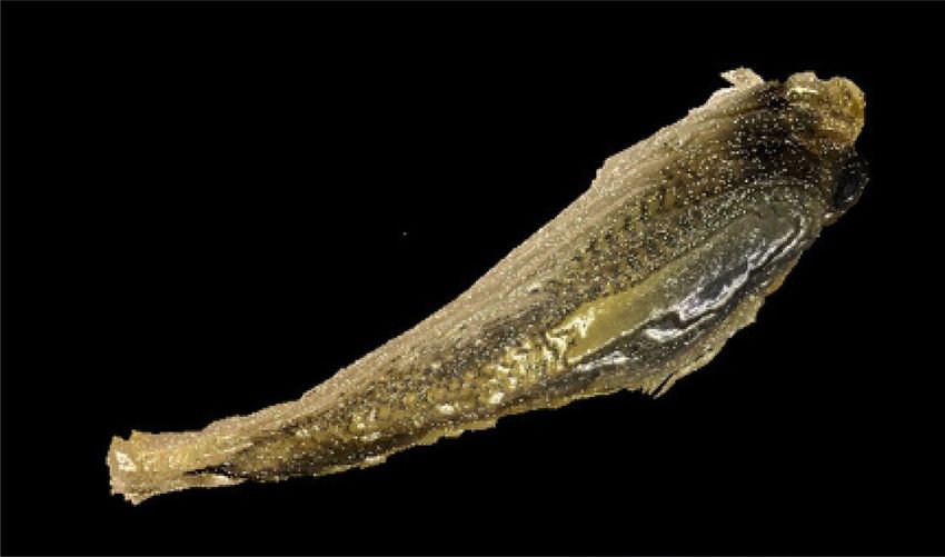
www.nature.com/scientificreports/
Figure 13. Knee joint of rabbit with titanium implant—surface image of milled cryogenic specimen.
surgical training on highly realistic digitized models is apparent21. The digital age can provide surgeons with
valuable materials for educational, practical and experimental purposes.
The described method and device for virtual reconstruction of biological objects is highly modifiable and
can be adjusted according to required researcher parameters. The milling nozzle can be interchanged depend-
ing on polishable material. We had experience with milling of a knee joint with a titanium implant present, no
procedural complications were noted (Fig. 13).
The camera and lighting can be changed according to researcher choice. Microscopic capturing of histologi-
cal material is possible by using microphotography capable cameras. Temperature control within the cryogenic
chamber can be modified, but is recommended to be maintained below − 25 °C, due to the formation of intra-
cellular ice at − 25 °C22. The distance between layers can be regulated by adjustment of device step parameters.
The cryogenic chamber volume can be modified. The method for cryopreservation, freezing and embedding
can be changed when required, but the algorithm of biological object preparation and virtual reconstruction
remains the same.
Increased availability of high quality imaging and real life morphology rendering will provide a valuable
source for educational, experimental and theoretical work. Our method of cryogenic biological object preparation
for virtual 3D reconstruction can provide a substantial input towards the development of educational databases,
surgical training models and virtual anatomical theaters.
Conclusions
Throughout a 20 year history of development, the cryogenic preparation and working conditions for layered
milling and virtual reconstruction using sequenced surface images has proven to be a successful method of
tissue-preserving biological object reconstruction in our practice. A minimization of tissue damage was seen
due to the characteristics of the preparation process. High modifiability of the proposed method provide vast
applicability and effectiveness. This technology has influenced the commencement of numerous projects on
virtual reconstruction of anatomical structures, modeling of surgical procedures and virtual pathology biobank
production. Overall, flash-freezing of biological objects with consequent embedding and secondary freezing
provide a highly stable model for sequenced layering and virtual reconstruction. The quality of the produced
images is exceptional, though depends on method of visualization, which can be modified according to researcher
preference. Consequent computerized modeling does not require specific software, and can be performed with
any system of choice, capable of working with an input of stacked images.
Materials and methods
All experimental protocols were carried out in accordance with relevant institutional and local guidelines and
regulations and were approved by I. M. Sechenov First Moscow State Medical University licensing committee.
Selection of biological objects. All biological objects were categorized into two groups. Group 1 included human
tissues, group 2 consisted of animal tissues. The animal and human tissues used during the development of
this method did not undergo any preparatory procedure prior to cryopreservation. All biological objects used
in this study were acquired from a university vivarium and pathology department and were not used in any
other experimental studies. The selection criteria for biological objects was not strictly defined, as the process
for virtual reconstruction with cryogenic sequenced layering does not require special preparation. Generally,
cryopreservation of biological objects was performed 2–48 h post-mortem. Biological objects with inclusions
of non-organic materials were not excluded from the experiment, though milling corrections were required.
Previously devitalized objects using formaldehyde vapors can be used.
To methodologically evaluate the advantages of this method, we performed a comparative morphometric
analysis of our method of cryogenic sequenced layering and classic histological slicing. 12 rat knee cartilage
reconstructions were prepared using the cryogenic sequenced layering method, and 12 rat knee cartilages were
prepared using fixation in 10% formaldehyde (pH = 7.4), decalcification with “Cal-Ex” (Fisher Scientific), fixed in
paraffin, staining with Hematoxylin & Eosyn and safranin O. Morphometric evaluation was carried out in accord-
ance with the principles of quantitative image analysis using the ImageJ free access software (USA, https://image
j.net). The radial thickness of the cartilage (μm), the surface factor (ratio of the length of the curved segment
corresponding to the actual border of the cartilage, between points at a distance of 100 μm from each other) and
the optical density of the extracellular matrix in the safranin O stain (conventional units). The first two indicators
could be determined on reconstructed 3D images. The optic density of the cartilage for 3D reconstructed images
Scientific Reports | (2020) 10:11899 | https://doi.org/10.1038/s41598-020-68682-z 10
Vol:.(1234567890)www.nature.com/scientificreports/
was calculated as the equivalent of the optical density of the ECM by the formula I = 0.299R + 0.587G + 0.114B,
where R, G and B are the average values of the color indicators in a selected area of cartilage. Quantitative data
was processed using the Statistica 10.0 program (StatSoft Inc., USA) with the calculation of indicators adopted
for the characterization of nonparametric samples in biomedical research: median [1st quarter, 3rd quartile]. To
prove the reliability of the differences, we used the variance analysis using the nonparametric Friedman crite-
rion for multiple groups (p < 0.05). The nonparametric Mann–Whitney test was used to analyze the differences
between the two independent samples.
Cryopreservation of biological objects. All models used in this experimental study underwent a simi-
lar process of flash-freezing, consequent embedding and secondary flash freezing. A cryogenic chamber, capable
of maintaining low working temperatures was used for preparation of biological objects. The dimensions of
the cryogenic chamber were 200 × 100 × 100 cm. No chemical treatment was used for preparation of biological
objects prior to embedding. Liquid nitrogen at a temperature of − 196 °C was used for flash-freezing of biological
material. All flash frozen biological material was maintained at a temperature below − 196 °C until further prepa-
ration was carried out. Flash-frozen and cryogenically stored biological objects underwent embedding with a
cryogenic medium. The Thermo Scientific Richard-Allan Scientific Neg-50 Frozen Section Medium was used for
embedding of biological objects. Biological tissue was placed in the medium within the cryogenic chamber and
flash-frozen as a compound and maintained at a working temperature of − 30 to − 35 °C.
Cryogenic milling device. The structure of the cryogenic milling device developed for this procedure is
available in Figs. 4, 5.23 The parameters required for proper functioning at cryogenic temperatures included
separation of the cryogenic chamber from automated components of the device. Therefore two separate sys-
tems were incorporated into one: the cryogenic system for the interaction between the biological object and the
mill, and the room-temperature system, which consisted of all other parts of the milling device. The specially
designed milling device can be reconstructed according to the figures and must be cryogenically capable, maxi-
mum rotational force at 5000 rpm. The cryogenic milling device in our study weighed approximately 4000 kg,
the high weight was mostly due to special anti-vibration additions to the structure. The step of sequenced mill-
ing was designed to provide as little as a 2–5 μm step between layers. This difference between layers is signifi-
cant enough for microscopic histological evaluation and more than sufficient for macroscopic reconstruction.
The default working step is 10 μm. With the given working parameters, constituted by the cryogenic chamber
dimensions (200 × 100x100cm), the speed of complete milling of the object (at a rate of 19–24 s per surface)
was approximately 48 h. Each mill passage is accompanied by temperature stabilization (cooling to working
temperature). The milling device structure accounts for possible seismic, vibrational and resonance hindrance.
Digitization. Photographic capturing of each consequent novel layer of the biological device was performed
after each mill passage step. Depending on the step, the number of images produced varied from 2000 to 25,000
per object. Digitization was carried out by a Canon 5D camera, alternatively Canon 5DSR camera. The instal-
lation of the camera is operator dependent, but automated. Any digital camera can be used for digitization, as
well as a microphotography camera (e.g. modified Canon digital LSR camera). Image capturing is performed
from outside the cryogenic chamber though an access window providing clear visualization of the surface of the
milled cryogenic model. The digital images are immediately transferred to a computer, where they are stored
and used for virtual reconstruction. The camera placement is outside the cryogenic chamber. Apart from the
camera, the digitization system includes lighting and stabilization features. Adaptation to new equipment is
easily performed, as even a hand held device is capable of digitizing surface images, though produced image
quality would be inconsistent. Overall, the entirety of image capturing is completely modifiable and depends
on researcher preferences. Most commonly, the following settings were used: Camera Canon 5D with Canon
EOS5D objective, with a pixel size 8 × 8 μm.
Virtual reconstruction. After digitization each image is simultaneously transferred to the computer for
storage and editing. For creating a three dimensional model from a series of layered images, we used Selena
software, version 8.0. Selena stores each image in .bio format according to position in the model (consecutively).
Any program allowing for modification, color management and three-dimensional rendering of stacked images
can be applied for virtual reconstruction. The choice of software was constricted by funding limitations and
can be changed according to researcher preference. Any software capable of working with an input of a series
of sequenced images and producing a three-dimensional model is necessary for virtual reconstruction of the
acquired data. This makes our method highly modifiable and accessible in different institutions, accommodating
for different approaches and processing techniques. Generally, the software carries out the task of image align-
ment, outline matching, manual optimization, scaling, multidimensional rotation, removal of molding material
(embedding medium), virtual slicing. The stacked images were acquired with nearly homogenous slice thick-
ness. Selena software alternatives that were considered, but could not be used due to funding restriction were:
Amira (available at https://www.thermofisher.com) and Imaris (available at https://imaris.oxinst.com), both
offering the ability for virtual reconstruction of an image sequence.
Computerized processing of the acquired images is performed through software based on Modex computing
core and has the ability to provide online 3D models with virtual slicing and sectioning in desired planes, con-
structing raster and wireframe models for source images of slices. The computational core implements algorithms
of analytic geometry and vector algebra to find lines of intersection of the surface of the wireframe model with
section planes. According to the raster model of the object, pixels are found that lie in a section, which in the
general case is a plane in general position. The cross-sectional textures are constructed using the geometrical
Scientific Reports | (2020) 10:11899 | https://doi.org/10.1038/s41598-020-68682-z 11
Vol.:(0123456789)www.nature.com/scientificreports/
Figure 14. Examples of Θ-plane in triangular sections.
parameters of the cross-section plane and the color characteristics of the pixels found. Since the wireframe model
of the object is a collection of faces defining the cross-section planes relative to the raster model, the general
texture of the entire model is determined in the same way.
Aspects of software processing. As a result of cyrogenic milling and surface image capturing, an image
sequence is created with a certain step (Δz), with a resolution determined by sample size and operator modified
camera settings. Further processing requires stacking of images and additional rendering, including creation of
plane-based sectioning ( of the reconstructed 3D object. In order to create plane-based sectioning, we introduce
a polygon plane (Θ-plane), which can be altered and transformed according to research goals (Fig. 14).
After applying the RGB color system, each element of the mapping color table (P) is considered as a vector
in three-dimensional space. Thereby, the vector field Ωv(x, y, z) = {R, G, B} within a region of the sample space
converts it into a color space. To construct an image on the sample slice plane, the Θ-plane of this section must
to be divided into pixels. Each pixel is associated with a color depending on its spatial position in a vector field
Ωv. A set of sliced images is the initial data: Zk = (k − 1) Δz , where the k-th image number (k = 1, …, M) is deter-
mined by the z-coordinate of the histological section. Consider a numbered set of raster images of size Px × Py,
where Px and Py are the numbers of pixels for the two corresponding sides. This initial set of images is designated
“digital set of base slices”. To reconstruct an object in the form of a three-dimmensional model, a method for color
interpolation in the space between each adjoining pair of images in the plains Zk and Zk+1 is specified. The entire
set of initial images is considered as a 3D matrix (P = (i,j,k)), whose elemens are individual pixels of images from
the set. Their addressing is determined by the number of the k-th layer (image sequence number), the number
of the i-th rowand the number of the j-th column in the matrix of pizels of the k-th photo. Discrete functions
defined on a three-dimensional grid (xi, yj, zk) are used. The statement that the vector ξ is orthogonal to the nor-
mal vector to the plane described by the equation Ax + By + Cz + D = 0 is equivalent tantamount to Aξx + Cξz = 0.
The vector η obeys the conditions of orthogonality to the vector ξ and the normal section plane. This means
that its direction can be computed as the vector product of the vector ξ by the normal vector to the section plane:
ex ey ez
η = [ξ , n] = det ξx ξy ξz ,
A B C
where n is the normal vector to the plane of the section, ex, ey, ez are the unit vectors along the positive direc-
tions of the x-, y- and z-axes respectively in the reference system associated with the sample. Taking into account
that vector ξ and η have a unit length, the following equations can be drawn out:
ξx2 + ξz2 = 1,
ηx2 + ηy2 + ηz2 = 1.
From these equations we can calculate the coordinate values of vecotrs ξ and η:
Scientific Reports | (2020) 10:11899 | https://doi.org/10.1038/s41598-020-68682-z 12
Vol:.(1234567890)www.nature.com/scientificreports/
Figure 15. Example of the incorporated virtual slicing algorithm on a biological model.
C A
ξ = √
2
, 0, − 2 ,
A + C2 A + C2
AB A2 + C 2 BC
η= − , ,− ,
L L L
2
L = A2 B2 + A2 + C 2 + B2 C 2 .
In the reference system associated with the section plane we denote p and q the unit vectors along the direc-
tion of the abscissa and ordinate axes, respectively. The vector p is orthogonal to the unit vector directed along
the applicate axis in the reference systome associated with the sample pz = 0, where pz is the projection of the
vector p onto the given axis. It is therefore required to add equations denotin the orthogonality of the vector p
to the normal vector to the plane of the section, and the orthogonality of the vector q to both of them, as well as
condition that the length of the vectors p and q is equal to one:
Apx + Bpy = 0,
ex ey ez
q = det ξx ξy ξz ,
A B C
�
px2 + py2 = 1,
�
qX2 + qy2 + qz2 = 1.
From these equations we can determine the values of the coordinates of the basis vectors in the reference
system associated with the sample:
B A
p = −√ ,√ ,0 ,
A2 + B2 A2 + B2
AC BC A + B2 2
q= − ,− , ,
M M M
M = A2 C 2 + B2 C 2 + A2 + B2 .
These equations specify the direction of the basis vectors of such reference system, associated with the cross-
section plane, for which the natural order of pixel bypass would guarantee the optimal number of calls to
information recorded on the hard disk. As a result cross sectioned images can be obtained from an image stack.
The incorporated algorithm results in a manageable and virtually sliceable three-dimensional model (Fig. 15).
Modeling software development. The software developed at out laboratory includes two main compo-
nents: graphical user interface (GUI) program and modules for virtual slicing of reconstructed model. Microsoft
Visual Studio 2012 comprising C# programming language with .NET framework 4.5 has been utilized as the
software development environment. The programming interface was refined by API WPF. Data input is des-
ignated by a user-selected source (file containing image sequence). Further setting of geometric parameters of
the sample are performed. Upon input, the program creates an object with specified dimensional characteristics
(length, width and depth) and plane object (frontal face of the reconstructed object). The normal vector is co-
directed with the OZ axis and applied to the origin—(0, 0, 0). The proposed method to construct vector 3D
models of samples that are necessary for theoretical modeling of processes in highly heterogenous biological
tissues can be applied using the given algorithm with any appropriate software.
Application of acquired data. Upon researcher request, our method provides a series of real-life quality
and texture images in any format, most commonly .TIFF, .JPG, .PNG. The image series can serve as basis for
Scientific Reports | (2020) 10:11899 | https://doi.org/10.1038/s41598-020-68682-z 13
Vol.:(0123456789)www.nature.com/scientificreports/
software layering and virtual reconstruction, animation, characterization, differentiation of tissue layers and
other numerous applications. Image quality is modifiable, default camera settings produced 4,368 × 2,912 pixel
images. Each image carries important topography-anatomical information, which is useful in modeling of sur-
gical procedure, educational visualization and diagnostics. Educational and diagnostic application of cryogenic
sequenced layering can be seen in the modeling of morphofunctional characteristics of the “joint-synovial fluid”
system, a published PhD thesis (available at https://dlib.rsl.ru/viewer/01008706918#?page=1).
Data assessment. Quality of tissue preservation was analyzed based on several factors: overall tissue integ-
rity, degree of tissue damage, presence of low-temperature deformities (such as crystallization), RGB-profile.
Subjective analysis of tissue integrity was performed. Computerized analysis of RGB-profile analysis was per-
formed using open access “ImageJ” software and Statistica 10.0 software for analysis of r esults24.
Received: 9 December 2019; Accepted: 30 June 2020
References
1. Tsang, V. L. & Bhatia, S. N. Fabrication of three-dimensional tissues. Adv. Biochem. Eng. Biotechnol. 103, 189–205. https://doi.
org/10.1007/10_010 (2007).
2. Wagner, T. A., Zahn, M., Grodzinsky, A. J. & Pascual-Leone, A. Three-dimensional head model simulation of transcranial magnetic
stimulation. IEEE Trans. Biomed. Eng. 51, 1586–1598. https://doi.org/10.1109/TBME.2004.827925 (2004).
3. Kolesky, D. B., Homan, K. A., Skylar-Scott, M. A. & Lewis, J. A. Three-dimensional bioprinting of thick vascularized tissues. Proc.
Natl. Acad. Sci. USA 113, 3179–3184. https://doi.org/10.1073/pnas.1521342113 (2016).
4. Antoni, D., Burckel, H., Josset, E. & Noel, G. Three-dimensional cell culture: a breakthrough in vivo. Int. J. Mol. Sci. 16, 5517–5527.
https://doi.org/10.3390/ijms16035517 (2015).
5. Sears, N. A., Seshadri, D. R., Dhavalikar, P. S. & Cosgriff-Hernandez, E. A review of three-dimensional printing in tissue engineer-
ing. Tissue Eng. B Rev. 22, 298–310. https://doi.org/10.1089/ten.TEB.2015.0464 (2016).
6. Bulyshev, A. E. et al. Computational modeling of three-dimensional microwave tomography of breast cancer. IEEE Trans. Biomed.
Eng. 48, 1053–1056. https://doi.org/10.1109/10.942596 (2001).
7. Ackerman, M. J. The visible human project: a resource for education. Acad. Med. 74, 667–670. https://doi.org/10.1097/00001888-
199906000-00012 (1999).
8. Cassirer, E. A. Celebration of the four hundredth anniversary of the De Humani Corporis Fabrica of Andreas Vesalius: the place
of vesalius in the culture of the renaissance. Yale J. Biol. Med. 16, 109 (1943).
9. Yamada, K. M. & Cukierman, E. Modeling tissue morphogenesis and cancer in 3D. Cell 130, 601–610. https://doi.org/10.1016/j.
cell.2007.08.006 (2007).
10. Chappelow, J., Tomaszewski, J. E., Feldman, M., Shih, N. & Madabhushi, A. HistoStitcher((c)): an interactive program for accurate
and rapid reconstruction of digitized whole histological sections from tissue fragments. Comput. Med. Imaging Graph 35, 557–567.
https://doi.org/10.1016/j.compmedimag.2011.01.010 (2011).
11. Encarnacion-Rivera, L., Foltz, S., Hartzell, H. C. & Choo, H. Myosoft: an automated muscle histology analysis tool using machine
learning algorithm utilizing FIJI/ImageJ software. PLoS ONE 15, e0229041. https://doi.org/10.1371/journal.pone.0229041 (2020).
12. Magee, D. et al. Histopathology in 3D: from three-dimensional reconstruction to multi-stain and multi-modal analysis. J. Pathol.
Inf. 6, 6. https://doi.org/10.4103/2153-3539.151890 (2015).
13. Dobosz, M., Ntziachristos, V., Scheuer, W. & Strobel, S. Multispectral fluorescence ultramicroscopy: three-dimensional visualiza-
tion and automatic quantification of tumor morphology, drug penetration, and antiangiogenic treatment response. Neoplasia 16,
1–13. https://doi.org/10.1593/neo.131848 (2014).
14. Hedvat, C. V. Digital microscopy: past, present, and future. Arch. Pathol. Lab. Med. 134, 1666–1670. https://doi.org/10.1043/2009-
0579-RAR1.1 (2010).
15. Alturkistani, H. A., Tashkandi, F. M. & Mohammedsaleh, Z. M. Histological stains: a literature review and case study. Glob. J.
Health Sci. 8, 72–79. https://doi.org/10.5539/gjhs.v8n3p72 (2015).
16. Schiemann, T. et al. Exploring the visible human using the VOXEL-MAN framework. Comput. Med. Imaging Graph. 24, 127–132
(2000).
17. Ackerman, M. J. The visible human project. J. Biocommun. 18, 14 (1991).
18. Sieber, D. et al. The OpenEar library of 3D models of the human temporal bone based on computed tomography and micro-slicing.
Sci. Data 6, 180297. https://doi.org/10.1038/sdata.2018.297 (2019).
19. Roy, D., Steyer, G. J., Gargesha, M., Stone, M. E. & Wilson, D. L. 3D cryo-imaging: a very high-resolution view of the whole mouse.
Anat. Rec. (Hoboken) 292, 342–351. https://doi.org/10.1002/ar.20849 (2009).
20. Parfitt, G. J. Immunofluorescence tomography: high-resolution 3-D reconstruction by serial-sectioning of methacrylate embedded
tissues and alignment of 2-D immunofluorescence images. Sci. Rep. 9, 1992. https://doi.org/10.1038/s41598-018-38232-9 (2019).
21. Andolfi, C., Plana, A., Kania, P., Banerjee, P. P. & Small, S. Usefulness of Three-Dimensional Modeling in Surgical Planning, Resi-
dent Training, and Patient Education. J. Laparoendosc. Adv. Surg. Technol. A 27, 512–515. https://doi.org/10.1089/lap.2016.0421
(2017).
22. Karlsson, J. O. & Toner, M. Long-term storage of tissues by cryopreservation: critical issues. Biomaterials 17, 243–256. https://doi.
org/10.1016/0142-9612(96)85562-1 (1996).
23. Terpilovskiy, A., Kuz’min, A. & Lukashkina, R. Sposob sozdaniya virtual’noy modeli biologicheskogo ob" ekta i ustroystvo dlya ego
osushchestvleniya: pat. 2418316 RF [Method for creating a virtual model of a biological object and a device for its implementation:
patent 2418316 RF]. Russ. Fed. 24 (2011).
24. Krylov, P., Nesmeyanova, E., Terpilovskiy, A. & Novochadov, V. Morphology of tibiofemoral joint in rats with experimental osteo-
arthritis: 3D-reconstruction, based on the technology of high-precision grinding. J. Anat. Histopathol. 6, 44–49 (2017).
Author contributions
V.N., T.A., K.A., L.R. conducted the experimental modeling and developed the project. S.A., A.S., K.E., L.G.
gathered the methodology, developed the programming and modeling methods. S.M., V.N, K.A. gathered raw
data and performed software modeling. S.M., T.A., A.S. prepared the manuscript. All authors reviewed the final
manuscript.
Competing interests
The authors declare no competing interests.
Scientific Reports | (2020) 10:11899 | https://doi.org/10.1038/s41598-020-68682-z 14
Vol:.(1234567890)www.nature.com/scientificreports/
Additional information
Correspondence and requests for materials should be addressed to V.N.N. or M.Y.S.
Reprints and permissions information is available at www.nature.com/reprints.
Publisher’s note Springer Nature remains neutral with regard to jurisdictional claims in published maps and
institutional affiliations.
Open Access This article is licensed under a Creative Commons Attribution 4.0 International
License, which permits use, sharing, adaptation, distribution and reproduction in any medium or
format, as long as you give appropriate credit to the original author(s) and the source, provide a link to the
Creative Commons license, and indicate if changes were made. The images or other third party material in this
article are included in the article’s Creative Commons license, unless indicated otherwise in a credit line to the
material. If material is not included in the article’s Creative Commons license and your intended use is not
permitted by statutory regulation or exceeds the permitted use, you will need to obtain permission directly from
the copyright holder. To view a copy of this license, visit http://creativecommons.org/licenses/by/4.0/.
© The Author(s) 2020
Scientific Reports | (2020) 10:11899 | https://doi.org/10.1038/s41598-020-68682-z 15
Vol.:(0123456789)You can also read