DESIGN, ANALYSIS AND PROTOTYPE DEVELOPMENT OF RAILWAY WAGONS ON DIFFERENT LOADING CONDITIONS
←
→
Page content transcription
If your browser does not render page correctly, please read the page content below
International Journal of Engineering Applied Sciences and Technology, 2020
Vol. 4, Issue 10, ISSN No. 2455-2143, Pages 122-129
Published Online in February 2020 in IJEAST (http://www.ijeast.com)
DESIGN, ANALYSIS AND PROTOTYPE
DEVELOPMENT OF RAILWAY WAGONS ON
DIFFERENT LOADING CONDITIONS
Shivendra Nandan, Rishikesh Trivedi, Satyajeet Kant, Javed Ahmad, M. Maniraj
School of Mechanical Engineering, Galgotias University,
Greater Noida, Gautam Buddha Nagar U.P State India.
Abstract- Indian Railway is a rapidly growing field of modeled as a rigid one. It is quite evitable that for such rigid models,
research, and extensive efforts are being spent with the aim the critical positions in context to ride comfort or safety of laden
of improving the reliability and availability of railway goods are the vehicle extremities, as at these locations the vertical
systems and of substantially reducing maintenance costs by motion of the whole body tends to sum up with the pitching motion
switching from time-based to event-driven maintenance of the car body. The results based on above assumptions of rigid
policies. This Project is aimed at proving that effective body often leads one to believe that vibration issues at the vehicle
Analysis can be applied also on already existing Railway extremities are more significant and should be addressed with
Wagons & Tracks. To do this, and focusing on National and priority. But the possibility of the magnitudes of the acceleration
International standards, we are going to develop a Designed levels at the center of vehicle floor being comparable with those at
prototype of Railway Coaches/Wagons for the different vehicle extremes cannot be neglected. With an ever increasing
loading conditions for optimum dimensions of wagon in demand for logistic support provided by railways, efforts to improve
consideration with balancing of tracks and platform speed in order to facilitate reduction in time for transport operation
loading-unloading of Rolling stock System. has received considerable attention. The past two centuries have
With a propose to design, develop, integrate, and test a seen increase in the travel speed from about 50 km per day by
Prototype of Railway Wagon & Tracks of Indian Railway horseback to about 650 km per day by car or 200-650 km per hour
that will have a conformable system for transportation of by using HSR. [1]
the locomotive/electric Engines. All the components of the
Coach or wagon of engine has been rolled out on the track.
Where we apply the vibration intensity ultrasonic testing
and this allowed to examine them and to assess if damage
indexes corresponded to actual faults. A huge amount of
data has been collected and it was possible to assess that the
overall system cannot be considered as in stationary
operation, neither when the train speed is constant nor
when the same track is travelled. Many different techniques
have been developed and tested with the aim of detecting
damages, design optimization via simulation, and material
research for the Accident Prevention.
Keywords: Tracks, Dynamic loading, Maintenance, Prototype,
Locomotives, Simulation, Balancing, Material Research &
Ultrasonic Testing.
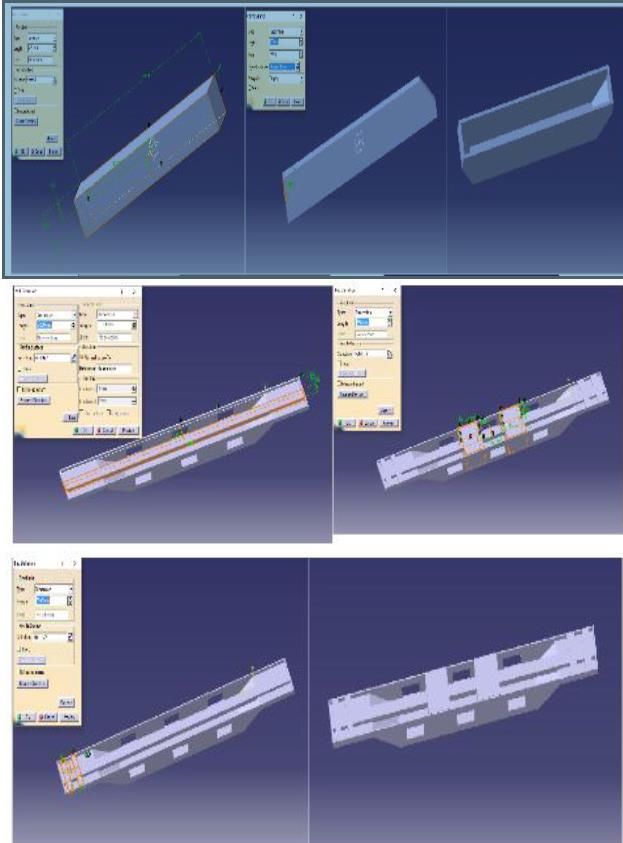
Fig 2.1 Schematic diagram of Railway bogie.
I. INTRODUCTION Many of the world’s railways face growing demands for both freight
and passenger transportation. Recent statistics for 2010 show a
1.1 Project background growth of worldwide rail freight ton kilometer’s by 3.4% and
Ever since the advent of railways, the rail tracks have been worldwide rail passenger-kilometers by 3.5% from the previous year
guiding the trains to operate in a safe manner. Further, 2010. As for the longer-term outlook, strategic goals and predictions
development ensured that the tracks played an important role in point to continued growth during the coming decades, as
economic aspects of railways. For the passage of the trains exemplified below. In Europe, the European Commission in its 2011
along the tracks to be smooth, the tracks need to be perfectly transport white paper sets out strategic goals to transfer freight
aligned as well as leveled; otherwise, the track irregularities transportation from road: “30% of road freight over 300 km should
may cause vibrations and oscillations. It has been seen all along shift to other modes such as rail or waterborne transport by 2030,
that, the major cause of discomfort for passengers has been due and more than 50% by 2050” [2].
to induced oscillation and vibrations. These vibrations and
oscillations are also a major source of damage to the laden A bogie is a wheeled wagon or trolley. In mechanics terms, a bogie
goods. The traditional dynamic analysis approach for railway is a chassis or framework carrying wheels, attached to a vehicle. It
vehicles has been based on the assumption that the car body is can be fixed in place, as on a cargo truck, mounted on a swivel, as
122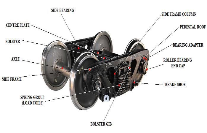
International Journal of Engineering Applied Sciences and Technology, 2020
                                Vol. 4, Issue 10, ISSN No. 2455-2143, Pages 122-129
                         Published Online in February 2020 in IJEAST (http://www.ijeast.com)

on a train carriage or locomotive, or sprung as in the suspension
of a caterpillar tracked vehicle (CTV). A bogie is a structure
underneath a train to which wheel axles (and, hence, wheels)
are attached through bearings. If they are used there are usually
two for each carriage, wagon and locomotive, or alternatively,
they are at the connections between the carriages or wagons.
The connections of the bogies with the cars allow a certain                                  Fig. 2.2: Railways-A Brief History.
degree of rotational movement around a vertical axis. Most
bogies have two axles, but some cars designed for extremely              The track kilometers in broad gauge (1676 mm) are 86, 526 kms,
heavy loads have been built with up to five axles per bogie.             meter gauge (1000 mm) of 63,028 kms, 16,001 km are electrified.
Heavy-duty cars may have more than two bogies using span
bolsters to equalize the load and connect the bogies to the cars.        2.2 Reviews
Usually the train floor is at a level above the bogies, however,         [3] B. Vinod Kumar et al. reviewed Prediction of Dynamic
for a double decker train the floor of the car may be lower              behavior of Railway vehicle by using prototype is very costly,
between bogies to increase interior space while staying within           lengthy and tedious task. Using virtual prototype of railway model
height restrictions [3].                                                 and running it in virtual environment for predicting dynamic
                                                                         behavior of railway vehicle model. At present steel material is used
                                                                         for hopper wagon, these are going to be replaced by aluminum alloy
               II.       LITERATURE REVIEW                               in the nearest future. To increasing load carrying capacity of freight
2.1 Introduction                                                         wagons, to reduce self-weight of freight wagon to reduce fuel
                                                                         required, to increase speed of the train in tangent track and in curve
Rail transport is the transport of passengers and goods by               passing, to increase comfort and safety of passenger coach. “B.
means of wheeled vehicles specially designed to run along                Vinod Kumar et al. (2017)”
railways or railroads. Rail transport is part of the logistics
chain, which facilitates the international trading and economic          [4] Krason Wieslaw et al. reviewed special wagon with a low
growth in most countries [1, 2].                                         rotatable loading platform for transportation. Allows quick and fast
A typical railway/railroad track consists of two parallel rails,         loading and unloading without any platform infrastructure or
normally made of steel, secured to cross-beams. The sleepers             terminals. Process of loading and unloading the trailers can be
maintain a constant distance between the two rails; a                    performed considering a whole train or individual wagons from any
measurement known as the 'gauge' of the track. To maintain the           part of the train (no cranes needed). To save time and money for
alignment of the track, it is either laid on a bed of ballast or else    road transport & reduction of the negative impact on the
secured to a solid concrete foundation, and the whole is referred        environment as well as an increase of road safety by reducing the
to as Permanent way [3-5].                                               number of vehicles on the roads. A strength test of the wagon
                                                                         structure was carried out & complete structure was estimated. For
Indian railways, the largest rail network in Asia and the world's        this purpose, numerical analysis was used. Applying repeatable
second largest under one management are credited with having             wagons-platforms with an automatic rotating body for fast, safe and
a multi gauge and multi traction system. Indian Railways have            easy loading and unloading of trucks Dynamic analyses of the
been a great integrating force for more than 150 years. It has           construction in different stages of its development were also carried
helped the economic life of the country and helped in                    out. Tests assume that a given system is composed of many stiff
accelerating the development of industry and agriculture [6].            modules joined with kinematic constraint. Individual modules of the
From a modest beginning in 1853, when the first train steamed            system are joined with a kinematic pair meant as an additional
off from Mumbai to Thane covering a distance of 34 kms, since            internal constraint in the form of moving joint. Determines a number
then there has been no looking back. It is interesting to note that      of degrees of freedom. All the modules constitute one system
though the railways were introduced to facilitate the                    defined as a multi-body system. The elements of the lock, in the
commercial interest of the British it played an important role in        close configuration are loaded mainly with longitudinal tensile and
unifying the country. Indian railways have grown into a vast             compressive forces. The purpose of the joint is also to relieve the
network of 7, 031 stations spread over a route length of 63, 221         central node, used mainly for positioning and rotation loading
kms with a fleet of 7,817 locomotives, 5,321 passenger service           platform of the wagon. “Krason Wieslaw et al. (2016)”
vehicles, 4, 904 other coaching vehicles and 228, 170 wagons             [5] S. V. GANORKAR et al. reviewed that Modern express trains
as on 31st March 2004.                                                   in India face the problem of having a higher floor level than the
Railways are ideally suited for long distance travel and                 current platform level. It is also seen in new rakes and coaches that
movement of bulk commodities. Regarded better than road                  there is a substantial gap in between the train floor and the platform.
transport in terms of energy efficiency, land use, environment           A simple construction of platform risers and gap fillers can make a
impact and safety it is always in forefront during national              huge difference. So from above problems, the solution is to use of
emergency.                                                               platform based ramps, platform based lifts, vehicle based ramps,
                                                                         vehicle based lifts, vehicle based internal lifts, etc. It is a good time
                                                                         to pause and reassess our strategy for providing sustainable. Assured
                                                                         and preferred logistics services to the nation and contribute towards
                                                                         nation building. As Improving overall customer satisfaction,
                                                                         Improving Reliability of Assets and Punctuality of Trains, Lowering

                                                                        123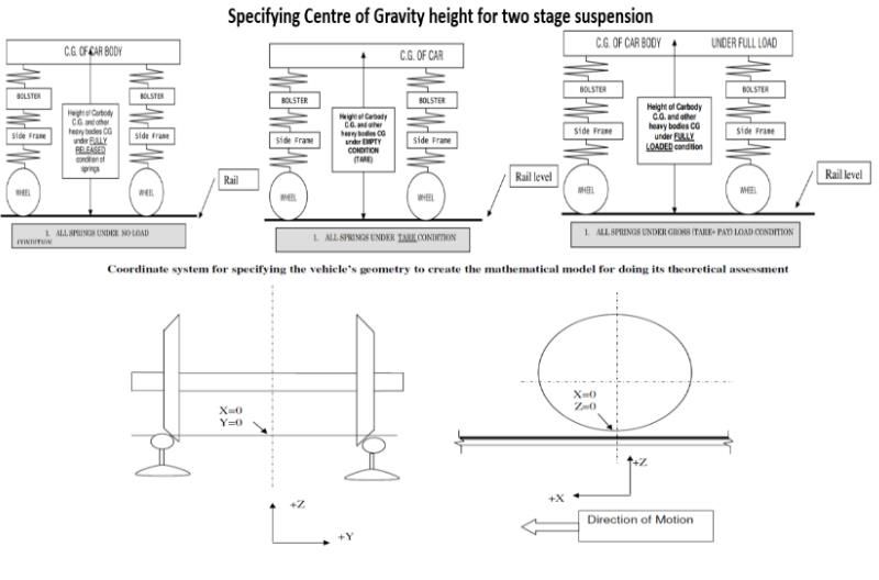
International Journal of Engineering Applied Sciences and Technology, 2020
                               Vol. 4, Issue 10, ISSN No. 2455-2143, Pages 122-129
                        Published Online in February 2020 in IJEAST (http://www.ijeast.com)

unit cost of operation for passenger and freight transports, to        structure. The methodology outlined in this paper requires a
improve margins and providing room to man oeuvre                       knowledge of the uncracked stress distribution in the component
competitive rates and services, Revenue enhancement by                 which contains a crack. In the process of crack propagating from its
increasing modal share of Railways in Passenger and Freight            initial length up to the critical crack length the cracks can grow in
transportation, Improving Cleanliness in Trains and at Stations,       three stages. “D. Peng et al. (2016)”
Enhancement in Security to prevent theft, pilferage and
                                                                       [9] Vladimir Milovanovic et al. reviewed that it describes a
sabotage, To develop design of new efficient wagons for
                                                                       methodology used to identify causes of cracking nearby the welded
upcoming transportation commodities like fly-ash, agricultural
                                                                       joint on the underframe of wagon type Symons for the
produce, milk, two wheelers etc. for Indian Railways necessary
                                                                       transportation of containers and swap. The aim of this analysis is to
to original innovative design solutions for Wagons for efficient
                                                                       identify and register the residual stresses that appear after the
loading/ unloading and transportation of new traffic
                                                                       process of mounting of the under-frame bottom part. The analysis
commodities. “S. V. GANORKAR et al. (2017)”
                                                                       was done to discover kind of loads which induce cracks in the
                                                                       welded joints. “Vladimir Milovanovic et al. (2015)”
[6] A.S. XUE et al. reviewed that Constraint effects of the
interference fits between wheels – axle and bearings – axle.           [10] Mehdi Koohmishi et al. reviewed that Ballast layer as sleeper
Integrated wheelset model of finite element method to calculate        support is a conventional railway track structure to transmit the train
the axle stresses. Maximum stress section is at outer side close       load into the underlying base courses as well to drain water outward
to wheel seat, different from the prediction of inner side close       to the track structure. Ballast fouling influence the mechanical
to wheel seat by the code analytic method. The loads set is            response of ballast materials by decreasing the shear strength of this
constructed from the vehicle dynamic behavior of the mass m1           layer and consequently reducing the stability of the railway track
above each wheelset with a vertical dynamic factor αv and a            structure. Contaminated ballast produces by adding sand to the clean
lateral dynamic factor αH, which are respectively defined as           aggregate sample, physical properties of considered ballast material
1) The stresses are not symmetrically by the axle central lateral      as well as rounded river aggregate. Each permeability test require
section (ACLS) along track direction. Bigger stresses are              approximately 3 hour to complete is specimen is first saturated for
inclined to the side with bigger loads of the wheelset.                24 hour prior to conducting the permeability test. The Effect of
                                                                       initial gradation of clean ballast as well as size of folding materials
2) The stresses are also not symmetrically by the axle vertical
                                                                       on the permeability of sand fouled railway ballast. “Mehdi
longitudinal section along axle axis. This is mainly due to
                                                                       Koohmishi et al. (2018)”
effects from the two longitudinal braking forces on the wheel
treads.                                                                [11] Lukas Lestinsky et al. reviewed that Noise reduction in
                                                                       railway vehicles is possible to achieve in multiple ways Proper
3) The stresses are still not symmetrically by the axle horizontal
                                                                       maintenance of the railway vehicle is very important as well. In
longitudinal section along axle axis. Bigger press stresses are
                                                                       general, it is very difficult to identify noise from basic variables and
inclined to the bottoms of sections. This should be mainly from
                                                                       technical drawing documentation Role of the simulation methods is
the gravity effect. “A.S. XUE et al. (2013)”
                                                                       to approximate to real life circumstances, which are seen in
[7] Stanislav Hodas et al. reviewed that the routes shown in           environment/nature. Simulation methods often use software with
the 3D model terrain surface. A designer that designs                  mathematical models, mostly derived from empirical formulas
reconstruction, modernization or newly built railway tracks            which were obtained from experiments. Noise and vibration
must consider the 3D design of digital design documentation            experiments are very important for noise reduction of railway
and design parameters of the currently valid standards. The            vehicles. Special role for the task fulfills modern FFT analyzers and
design parameters of the railway line project and the optimized        manually-operated analyzers (digital acoustic measurement
location of this track body are closely related. The track             instruments). Record of noise levels – minimal, maximal, levels
designer must also consider the weight which will be                   with different time characteristics and different weight filter during
transported on the track. The design works include complicated         every measurement. “Lukas Lestinsky et al. (2019)”
procedures, while the railway track components must comply
                                                                                       III.     PROBLEM DESCRIPTION
with all design criteria of the currently applicable standards and
regulations. The directional curvature of railway track including      Presently, the non-containerized payload carried by Indian Railways
basic specifications of its structural elements such as curve radii    is largely dominated by Coal, Iron Ore, Cement, Steel Products,
(blue), shape and length of transition spirals (green), straight       Fertilizers, Petroleum products, etc. These lines of businesses are
sections between the curves (red), etc., must be consistent with       stagnating and Indian Railways is considering alternate commodities
the design values of railway track according to STN or STN             for transportation across the countries. Some such commodities are
EN. “Stanislav Hodas et al. (2015)”                                    to cater to such emerging markets, Indian Railways requires new
                                                                       designs of wagons to ensure that the emerging business is not lost to
[8] D. Peng et al. reviewed that a hopper wagon is a type of
                                                                       other modes of transportation. The Project is to innovative design
railroad freight car used to transport many types of materials
                                                                       for solutions for Wagons for efficient loading/ unloading and
such as coal, ore, grain, ballast and minerals and bulk cargo etc.
                                                                       transportation of new traffic commodities. The solution should
In any such analysis the stress intensity factors at crack tips are
                                                                       include the design and efficient method of loading and unloading of
important parameters for estimating both residual life and
                                                                       commodities for safe handling and swift turnaround duly
criticality (residual strength). The advantage of the present
                                                                       maximizing the transport of commodities per unit time and cost,
approach is that it negates the need to explicitly model cracks.
                                                                       taking into account the current constraints of fixed infrastructure.
A crack of any size can be analyzed using the original (un-
cracked) finite element model. It is a complicated welded
                                                                      124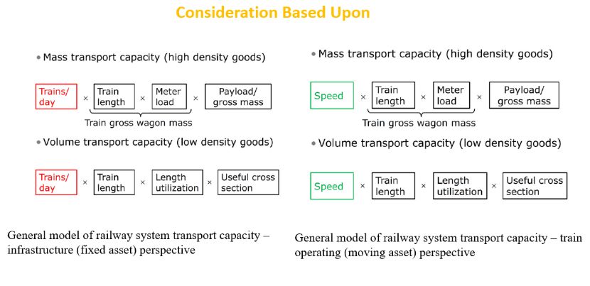
International Journal of Engineering Applied Sciences and Technology, 2020
Vol. 4, Issue 10, ISSN No. 2455-2143, Pages 122-129
Published Online in February 2020 in IJEAST (http://www.ijeast.com)
3.1 Area: Design Analysis and Prototype Development Use of low rotatable loading platform with an automatic
rotating body
3.2 Title: Design, Analysis & Prototype Development of To use of platform-based ramps, platform-based lifts, vehicle-
Railway Coaches (or) wagons on different loading conditions based ramps for providing sustainable, assured and preferred
for optimum dimensions of coach in consideration with logistics services.
balancing of tracks & Platform loading-unloading system. Increasing average speeds of passenger and freight trains and
reducing overall transit time By Finding Optimum Weight-
3.3 Aim: Design of Railway Coach/Wagon by To Develop an Speed ratio.
efficient Prototype model of Modern Rail for effective with intensive utilization of existing assets and efficient
Transportation. management of constraints
Integrated wheelset model of finite element method to
3.4 Motivation: calculate the axle stresses
Need of improvement of Design for Sustain and Consider the weight which will be transported on the track.
Economical Factor. Analysis the stress intensity factors at crack tips are important
Material Research such as Aluminum which has more parameters for estimating both residual life and criticality
strength. (residual strength).
Reduce Delays of Train Schedules Identify causes of cracking nearby the welded joint on the
Accident Prevention by Vibration Intensity Ultrasonic underframe of wagon type Symons for the transportation of
Testing containers and swap.
Up gradation in the guide lines of Standards and Conducting Noise and vibration experiments for noise
Specifications for Railway Wagons. reduction of railway vehicle
Due to increase in the population, Need in Design This ultimately increases the Life Cycle of Railway wagons
Improvement for Optimum space availability and Comfort with enhanced safety features.
of Passenger.
3.6 Objective of Project
3.5 Problem description The main aim of this project is to develop much cleaner cost-
All developing or developed countries requires newly- effective way of power generation method power generation and
standardized Transport for daily transportation of passenger, accident prevention by vibration intensity ultrasonic testing and
Goods, Industrial raw materials and Produced products in which also helps in automatic unmanned railway gate controlling as
almost all cities by means of Railway Transport. Because well as moving platform-based stock rolling loading and unloading
the increase in use, most existing systems are not sustainable system.
and economical for Transportation. Because of Lack of
innovation in railway and also old guide lines of Standards and Prediction of Dynamic behavior of Railway vehicle by using
Specifications for Railway Wagons. As well as Due to increase prototype is very costly, lengthy and tedious task so, now a day
in the use of railway as transport method causes less space most of the railway companies and researchers are using virtual
availability, Accidents, Noise causes, Cracks due to Vibration prototype of railway model and running it in virtual environment for
and Delays in loading-unloading scheduling. predicting dynamic behavior of railway vehicle model.
In the current scenario of Indian Railway – There is some popular software available for modelling like auto
cad & pro-e, predicting dynamic behavior of vehicle model such as
Less Track Maintenance and Poor state of Track Lines. Ansys, Universal Mechanism etc. At present steel material is used
Railway Accidents Due to Wagon Design Balancing Of for hopper wagon, these are going to be replaced by aluminum alloy
tracks. in the nearest future. In present work, I have designed and assembly
Lack of modern techniques used in the Design and Blue- of a proto type model of fright hopper wagon using CAD
Prints Preparation. application In PRO-E or CATIA software etc.
Less strength of Single tracks with respect to Weight-
We will perform linear mode shape modelling and design by hopper
Speed ratio of Trains.
wagon on track. As the aluminum alloy has greater strength and less
Because of Lower Track Strength and heavy Wagons
self-weight, less fuel will be used in transportation and vertical force
Speed reduces of trains and Delays in Train Timing
is reduced, hence less wear.
Schedules.
IV. RESEARCH PURPOSE AND MEANING
In this Project, We are using virtual prototype of railway model
and running it in virtual environment for predicting dynamic The purpose of the new wagon design was to maximize the
behavior of railway vehicle Wagon model. At present steel versatility of the concept to allow containers, swap bodies,
material is used for hopper wagon these are going to be Passenger trains and trailers to be moved freely on a common form
replaced by aluminum alloy in the nearest future. of rail vehicle within most of the standard gauge rail network in
Transport. Existing wagons were less versatile in relation to their
ability to accommodate a mix of inter-modal modules (IMM). The
The Problems related to railway wagon is eliminated by new design has much greater versatility.
Decrease in capital cost of railway by optimum design.
125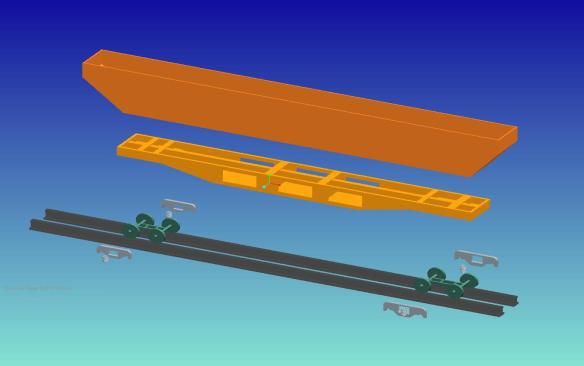
International Journal of Engineering Applied Sciences and Technology, 2020
Vol. 4, Issue 10, ISSN No. 2455-2143, Pages 122-129
Published Online in February 2020 in IJEAST (http://www.ijeast.com)
To get More Space availability in the Coaches.
Using material research selection which can give higher The material properties assigned for hopper wagon are considered
strength with reduce weight of the Wagon. by density values.
Continuous Ultrasonic testing of track
For Checking of cracks and Balancing of tracks. Modeling: according to dimensions the model of hopper wagon
Suitable Transport Design for Increasing Population. made up of steel and aluminum, the mass momentum of the car
Reducing Vibration of wagon as well as Tracks at High body, wheel axle set are been designed by using pro/e software and
speeds. cad software. From the comparison of steel and aluminum material
To Find Optimum Variables on Different type of matter hopper wagon alloy of these two gives the best result of having the
liter weight, less stress acting is acting due to this the train is going
transportation (Such as Oil, CNG Gas, Coal, Pesticides
to move in the safe way.
and Passenger Transport.
Get best speed and load ratio on various condition of
weather (i.e. winter, summer, Spring Season, Rainy Days
etc.).
4.1 Components of railway wagon
It comprises the Bogie frame.
The bogie frame has the Axle and wheel arrangements.
The SUSPENSION system.
The BRAKING system.
4.2 Assembling of railway wagon
Hopper wagons can only be unloaded by gravity with no
external assistance and are therefore also classed as self-
discharging wagons. The majority may be filled, when at rail or
road level, by high-level discharge chutes (whose ends are more
than 70 cm above the top of the rails) or conveyor belts.
Fig 4.2 Modelling of a railway wagon using software.
Assembly: the assembly includes the combining of the all the parts
Fig 4.1 Assembled parts of wagon by using software. which are designed or modeled from the pro/e this assembled part
further goes to the analysis hear the two types static analysis and
Because a controlled amount of the load can be discharged at dynamic analysis. From static analysis the maximum von mises
any place the wagons may be sent anywhere and are even used stress value and maximum comparing von-mises with yield stress of
individually. Railway companies also use hoppers as material, factor of safety can be calculated. And from the dynamic
departmental wagons in maintenance of way trains for analysis values of the lateral and vertical forces, derailment quotient,
ballasting the track. longitudinal and lateral creep forces coming on tangent and curve
track.
4.3 Analysis and Simulation
In present work, hopper wagon can be made of different 4.4 Load Calculations
Materials like steel and aluminum analyzed by During design stage, possible loads are regularized by a design
a) Dynamic Analysis code. For the present axle, the loads by the code EN 13103 are
b) Static Analysis applied. As shown as in Fig. 1, the loads set is constructed from the
vehicle dynamic behavior of the mass m1 above each wheel set with
The step followed is as under: a vertical dynamic factor αv and a lateral dynamic factor αH, which
1. Modeling are respectively defined as
2. Assigning Material properties
3. Boundary Conditions
126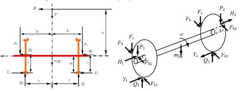
International Journal of Engineering Applied Sciences and Technology, 2020
                             Vol. 4, Issue 10, ISSN No. 2455-2143, Pages 122-129
                      Published Online in February 2020 in IJEAST (http://www.ijeast.com)

                                                            4.5 Design Methodology:
                                                            These are the Steps which are involved in Design
                                                            4.5.1 Deviation of Problem into modules
Where g is gravity acceleration, and the mass m1 can be
deduced as                                                  Various stages involved in new wagon design are as under:
                    m1 = (2P – m2g)/g
                                                                  a) Stage I - Concept Design
                                                                  b) Stage II - Detailed Design
Using the sample wagon parameters, the loads set for the
                                                                  c) Stage III - Prototype Manufacturing, Testing, Design
present check of axle reliability is given:
                                                                     Validation & Optimum Speed
                                                                  d) Stage V - Introduction of new Wagons in Open Line

                                                            Criteria for wagon Design (or) Design Methodology:
                                                            Stage I - Concept Design:
                                                             •    General arrangement diagram
                                                             •     Necessary drawing showing dimensions of the wagons
                                                             •     Type of Commodity and load distribution
              Fig 1.5 Arrangement of wheels.                 •     Design considerations like factor of safety, dynamic augment,
                                                                  fatigue allowance criteria (general or component specific)
                                                             •    Fatigue life of components in Kms or in number of Years.
                                                             •    Suitability of loading/unloading methods and equipment for
                                                                  the existing facilities on IR system.
                                                             •    Type of Material used in Wagon Construction i) Type of
                                                                  Wagon: General Purpose, Commodity Specific, Route Specific
                                                             •     Precaution which should be taken for the complete cycle from
                                                                  loading to unloading to take care
                                                             •     Of the working conditions/problems in the proposed design.
                                                            Stage II - Detailed Design.
                                                             a.) Wagon body
                                                                 i) Product structure plan, which shows how the key elements
                                                                     such as components, sub-assemblies & assemblies form the
                                                                     final product.
                                                                 ii) Design drawings of key elements which show the main
                                                                     principle of design accompanied by a short description & as
                                                                     far as necessary for understanding of the design.
                                                                 iii) Criteria for the selection of materials & methods for their
                                                                       evaluation. (If such materials are in use in other existing
                                                                       wagons, it should be mentioned.)
                                                                 iv) Details of various structural joints.
                                                                 v) Minimum use of riveting shall be made. The DP should
                                                                    submit details for justifying the requirement/necessity of
                                                                    riveting in the wagon design.
                                                            b.) Bogie, including its components e.g. axle bearing, wheel & axle,
                                                                etc.
                                                            c.) Brake system the wagon shall be fitted with graduated release
                                                                air brake system as per the latest specifications. The brake
                                                                linkage can be under frame/body or bogie mounted
                                                                arrangements.
                                                            d.) Coupler & draft gear the proposed wagon designs shall be with
                                                                standard coupler and draft gear to specification compatible, as
                                                           127
International Journal of Engineering Applied Sciences and Technology, 2020
Vol. 4, Issue 10, ISSN No. 2455-2143, Pages 122-129
Published Online in February 2020 in IJEAST (http://www.ijeast.com)
per standard specifications.
B. Overall Dimensions (millimetres)
e.) Loading and unloading systems
1. Length over coupler faces
i) Details of operation and fitment of loading and 2. Inside Length
unloading systems on the proposed wagon design 3. Length between bogie centres
ii) The above-mentioned details to be given for each type 4. Length over head stock
of commodity to be transported by the proposed wagon. 5. Coupler height over level Track from rail level
6. Overall Width
iii) Details of Manufacturer of the loading and unloading 7. Inside Width
systems. 8. Floor height from rail level
9. Inside height
10. Volumetric Capacity (in cubic meter)
Stage III - Prototype Manufacturing, Testing and design 11. Volumetric Capacity of heap Loading (in cubic meter)
Validation & Provisional Speed. 12. Total Volumetric Capacity (in cubic meter)
a) Standards used for design and calculation
4.5.3 TECHNICAL DATA OF THE PROPOSED WAGON
b) Computer programs used for design & calculation DESIGN
c) The test schedule should reflect material, components, sub Table 4.2. Technical Data
– assemblies, assemblies & the finished product and will
distinguish between: o Type acceptance tests, Production Following technical data of proposed wagon designed shall
be submitted
Tests & Quality Check Tests o Test on first article or on
1. Weight centre of gravity of each component and also CG of the
further wagons with test sequence o Location of test site equipment installed on the wagon body.
i.e. contractors works, etc. 2. Weight distribution indicating lateral longitudinal unbalance,
3. Balancing calculation for the wagon
Stage IV- Oscillation Trial. 4. Method of adjusting of wheel/axle load
Oscillation trials of the prototype wagon shall be conducted to 5. Calculation of unsprung mass
6. Vogel’s layout for 10 degree curve and for 1 in 8.5 turnout for
confirm that the design will exhibit running characteristics as
bogie negotiability
per the limits specified by Criteria. 7. Throw-over at head-stock/wagon and coupler movements
together with details of clearance.
8. Estimation of flange forces on curves and turnouts
Stage V - Introduction of new Wagons in Open Line. 9. Stress analysis of all major stress bearing parts of the under
frame under static & dynamic conditions
Any design modification be required to be made in any part of
10. Calculation for energy absorption
the equipment at any time, it will be advised to the DP, who 11. Projected dynamic augmented with the unsprung masses as
will ensure its compliance for the existing wagons and new used with the IR Track
wagons, under manufacture. 12. Stability calculation
13. Vibration analysis of the wagon body and the natural
frequencies.
4.5.2 BASIC DESIGN PARAMETERS OF PROPOSED
WAGON DESIGN
V. ECONOMICAL FEASIBILITY
This method is completely in the favor of Prototyping economy; its
Table 4.1. Parameters Specifications components are designed by software and can be easily assembled.
By using this method we can save time and part of money in field of
Parameters wagon prototyping.
A. General
1. Axle Load (in tonnes) VI. CONCLUSION
2. TLD (in tonnes/meter) Modelling: according to dimensions the model of hopper wagon
3. Tare weight of complete wagon (in tonnes) made up of steel and aluminium, the mass momentum of the car
4. Payload of a wagon (in tonnes) body, wheel axle set are been designed by using pro/e software and
5. Payload to tare weight ratio cad software. From the comparison of steel and aluminium material
6. Numbers of wagon in 626 meter length hopper wagon alloy of these two gives the best result of having the
7. Payload of rake in 626 meter length (in tonnes) litter weight, less stress acting are acting due to this the train is
8. Height of C.G. in empty and loaded conditions for going to move in the safe way.
commodities proposed to be loaded (in millimetres)
9. Commodity for which wagon is designed Assembly: the assembly includes the combining of the all the parts
10. Other commodities, which may be carried in the which are designed or modelled from the pro/e this assembled part
wagon further goes to the analysis hear the two types static analysis and
dynamic analysis. From static analysis the maximum von mises
128International Journal of Engineering Applied Sciences and Technology, 2020
Vol. 4, Issue 10, ISSN No. 2455-2143, Pages 122-129
Published Online in February 2020 in IJEAST (http://www.ijeast.com)
stress value and maximum comparing von-mises with yield and helped me a lot in gathering different information, collecting
stress of material, factor of safety can be calculated. And from data and guiding me from time to time in making this project,
the dynamic analysis values of the lateral and vertical forces, despite of their busy schedules, they gave me different ideas in
derailment quotient, longitudinal and lateral creep forces making this project unique.
coming on tangent and curve track from the comparison of steel
VIII. REFERENCES
and aluminium material hopper wagon, the percentage
reduction in vertical and normal forces, longitudinal and lateral 1. S. S. Harak, S. C. Sharma, S. P. Harsha (2014).
creep forces by using aluminium material of is calculated. Structural dynamic analysis of freight railway wagon using finite
Reduction in wheel set vertical force is 8.2% element method. Procedia Materials Science 6 ( 2014 ) 1891 –
Reduction in lateral creep force is 4.6 to 7.32 % 1898.
Reduction in longitudinal creep force is 5.99 to 7.65% 2. H. E. Boysen (2012). General model of railway. WIT
Reduction in wheelset normal force is 4.7 to 8.5% Transactions on The Built Environment, Vol 127, ISSN 1743-3509
So it is to be conclude from the above results that aluminium is (on-line) 335-347
better and economical than steel.
Present Conflict 3. B. Vinod Kumar, M.Suneetha, Dr.N.Venkatachalapathi
(2017). Modeling and Analysis of Railway Wagon. International
By using this process, A real time analysis of protype is to be journal & magazine of engineering, technology management and
find which reflects the optimized environment for analysis and research Vol. 4 issue 11 403-407.
according to that the Prototype can be developed at the
minimum of cost and time. 4. Krason Wieslaw et al. (2016). Innovative project of
prototype railway wagon and intermodal transport system.
Future Scope Transportation Research Procedia 14 ( 2016 ) 615 – 624.
To increasing load carrying capacity of freight wagons, to 5. S. V. GANORKAR et al. (2017). Innovation Challenge
reduce self-weight of freight wagon to reduce fuel required, to For Indian Railways. Journal Of Information, Knowledge And
increase speed of the train in tangent track and in curve passing, Research In Mechanical Engineering Vol. 4 (2017) 879-887
to increase comfort and safety of passenger coach. So we can
use this method for different types of wagons and virtual 6. A.S. XUE ET AL. (2013). Design Reliability Assessment
software analysis of prototype of wagons can be done. on the Railway Wagon Axle with 30 TonAxle Weigh. Advanced
Materials Research Vol. 658(2013) 323-326
7. Stanislav Hodas et al. (2015). Design of Railway Track
VII. ACKNOWLEDGEMENT for Speed and High-speed Railways. ScienceDirect 332-343
We are over helmed in all humbleness and gratefulness to 8. D. Peng, R. Jones and D. Hui (2016). An Engineering
acknowledge our depth to all those who have helped me to put Approach To The Fracture Assessment Of Hopper Wagons. An
these ideas, well above the level of simplicity and into Engineering Approach To The Fracture S0013-7944(16)30432-5
something concrete. 432-48
We would like to express our sincere gratitude to our Guide Dr. 9. Vladimir Milovanovic´ ⇑, Vladimir Dunic´ , Dragan
M. Maniraj & Industrial Guide Mr. Vishal Pratap Singh for Rakic´, Miroslav Zˇ ivkovic (2015) Identification causes of
providing their invaluable guidance, comments and suggestions cracking on the underframe of wagon for containers transportation –
throughout the course of the project. We have taken efforts in Fatigue strength assessment of wagon welded joints. Engineering
this project. However, it would not have been possible without Failure Analysis 31 (2013) 118–131
the kind support and help of many individuals and organization
Faculties. Whose guidance, encouragement, Suggestion and 10. Mehdi Koohmishi et al. (2018) Effect of gradation and
very constructive criticism have contributed immensely to the size of foulding materials on hydraulic conductivity of sand-fouled
evolution of ideas on project. We would like to extend our railway ballast. Journal of Construction and building material Vol.
sincere thanks to all of them. 6 (2018) 89-97
We are highly indebted to Project Co-Coordinator Mr. Srikant 11. Lukas Lestinsky et al. (2019) New methods of noise
Vidya for their guidance and constant supervision as well as for reduction in railway carriages. Transportation Research Procedia
providing necessary information regarding the project & also 40 (2019) 778-783.
for their support in completing the project.
We would like to express my gratitude towards Faculty
member of Galgotias University for their kind co-operation and
encouragement which help me in completion of this project.
We would like to express my special gratitude and thanks to
Lab and Workshop In-charges for giving me such attention and
time.
Our thanks and appreciations also go to my colleague in
developing the project and people who have willingly helped
me out with their abilities.
129You can also read