Design of a Shoulder-Launched Anti-UAV Missile System - AIAA
←
→
Page content transcription
If your browser does not render page correctly, please read the page content below
Design of a Shoulder-Launched Anti-UAV Missile System
             William Giffin 1 , Margaret Kilpatrick 2 , Ted Vlady 2 , Brenton J. Willier 2 , Nicholas Brophy 3 ,
              Justin Dobbin 3 , Sofia Ocoro Giraldo 3 , James Jutras 3 , Nguyen Nguyen 3 , Jose Romero 3
                                         Aerospace Systems Design Laboratory
                      Georgia Institute of Technology, Atlanta, Georgia, 30332, United States

1 GraduateStudent, Georgia Tech, AIAA Student Member
2 GraduateResearch Assistant, Aerospace Systems Design Laboratory, AIAA Student Member
3 Undergraduate Student, Georgia Tech, AIAA Student Member
Dr. Dimitri Mavris            Dr. Brad Robertson                      Dr. Adam Cox
  Faculty Advisor               Research Advisor                      Research Advisor

 William Giffin       Margaret Kilpatrick              Ted Vlady            Brenton Willier
   Structures             Propulsion                  Trajectory             Aerodynamics
      ASDL                   ASDL                        ASDL                    ASDL
AIAA #: 1230548        AIAA #: 1230547              AIAA #: 921865          AIAA #: 1218364

  Nicholas Brophy                 Justin Dobbin                      Sofia Ocoro Giraldo
     Propulsion                     Trajectory                         Aerodynamics
  Undergraduate                  Undergraduate                         Undergraduate
  AIAA #: 1230678                AIAA #: 923006                       AIAA #: 1229424

    James Jutras                Nguyen Nguyen                           Jose Romero
     Structures                    Trajectory                            Trajectory
  Undergraduate                 Undergraduate                         Undergraduate
  AIAA #: 1229357               AIAA #: 1146928                       AIAA #: 1146929
Executive Summary

The ISLAND missile is a low-cost missile system that is specially designed to destroy Type 1 and Type 2 UAVs. It has

a design range of 3.5 nautical miles and a design altitude of 5,000 feet. The system design, from the bottom up, was

focused on user safety. Launch noise was minimized to a peak of 151 dBA, through the use of a custom first stage low

noise rocket motor and through various noise mitigation techniques. ISLAND’s noise levels are well below similar

systems. The launch acceleration and the exhaust gases were mitigated through the use of an ejectable launch motor.

The goal of the ISLAND missile system is to prevent asymmetric warfare, specifically against small UAV targets. The

low cost seeker, simple materials, and commercial off the shelf ejectable launch motor allow ISLAND to meet this

goal, with a acquisition price of only $35,000. Further orders of the ISLAND system can drive the price to below

$25,000, similar in price to the Raytheon Coyote and over $10,000 cheaper than the Stinger. 3-D CAD renderings of

the ISLAND missile and launcher are shown below.

Table of Contents
Table of Contents                                                                                                                                                                 i

List of Figures                                                                                                                                                                  iii

List of Tables                                                                                                                                                                    v

1   Introduction                                                                                                                                                                  1
    1.1 Project Introduction . . . . . . . . . . . . . . . . . . . . . . . . . . . . . . . . . . . . . . . . . . . .                                                              1
    1.2 Background and Existing Systems . . . . . . . . . . . . . . . . . . . . . . . . . . . . . . . . . . . .                                                                   1
    1.3 Target Characterization . . . . . . . . . . . . . . . . . . . . . . . . . . . . . . . . . . . . . . . . . .                                                               3

2   Requirements                                                                                                                                                                  4
    2.1 Explicit Requirements . . . . . . . . . . . . . . . . . . . . . . . . . . . . . . . . . . . . . . . . . .                                                                 4
    2.2 Derived Requirements . . . . . . . . . . . . . . . . . . . . . . . . . . . . . . . . . . . . . . . . . .                                                                  5
    2.3 Concept of Operation . . . . . . . . . . . . . . . . . . . . . . . . . . . . . . . . . . . . . . . . . . .                                                                6

3   Configuration Analysis                                                                                                                                                        7

4   Approach                                                                                                                                                                     10
    4.1 Geometry . . . . . . . . . . . . . . . . . . . .     .   .   .   .   .   .   .   .   .   .   .   .   .   .   .   .   .   .   .   .   .   .   .   .   .   .   .   .   .   10
    4.2 Weights, Structures, and Cost . . . . . . . . . .    .   .   .   .   .   .   .   .   .   .   .   .   .   .   .   .   .   .   .   .   .   .   .   .   .   .   .   .   .   11
        4.2.1 Weight Analysis . . . . . . . . . . . .        .   .   .   .   .   .   .   .   .   .   .   .   .   .   .   .   .   .   .   .   .   .   .   .   .   .   .   .   .   11
        4.2.2 Structural Analysis . . . . . . . . . . .      .   .   .   .   .   .   .   .   .   .   .   .   .   .   .   .   .   .   .   .   .   .   .   .   .   .   .   .   .   13
        4.2.3 Factor of Safety Calculation . . . . . .       .   .   .   .   .   .   .   .   .   .   .   .   .   .   .   .   .   .   .   .   .   .   .   .   .   .   .   .   .   14
        4.2.4 Material Selection . . . . . . . . . . .       .   .   .   .   .   .   .   .   .   .   .   .   .   .   .   .   .   .   .   .   .   .   .   .   .   .   .   .   .   14
        4.2.5 Cost and Manufacturing . . . . . . . .         .   .   .   .   .   .   .   .   .   .   .   .   .   .   .   .   .   .   .   .   .   .   .   .   .   .   .   .   .   15
    4.3 Propulsion . . . . . . . . . . . . . . . . . . . .   .   .   .   .   .   .   .   .   .   .   .   .   .   .   .   .   .   .   .   .   .   .   .   .   .   .   .   .   .   15
        4.3.1 Solid Rocket Motors . . . . . . . . . .        .   .   .   .   .   .   .   .   .   .   .   .   .   .   .   .   .   .   .   .   .   .   .   .   .   .   .   .   .   16
    4.4 Aerodynamics . . . . . . . . . . . . . . . . . .     .   .   .   .   .   .   .   .   .   .   .   .   .   .   .   .   .   .   .   .   .   .   .   .   .   .   .   .   .   18
        4.4.1 Missile Body . . . . . . . . . . . . . .       .   .   .   .   .   .   .   .   .   .   .   .   .   .   .   .   .   .   .   .   .   .   .   .   .   .   .   .   .   18
        4.4.2 Missile Control Surfaces . . . . . . . .       .   .   .   .   .   .   .   .   .   .   .   .   .   .   .   .   .   .   .   .   .   .   .   .   .   .   .   .   .   20
        4.4.3 Missile Stability . . . . . . . . . . . .      .   .   .   .   .   .   .   .   .   .   .   .   .   .   .   .   .   .   .   .   .   .   .   .   .   .   .   .   .   21
    4.5 Trajectory . . . . . . . . . . . . . . . . . . . .   .   .   .   .   .   .   .   .   .   .   .   .   .   .   .   .   .   .   .   .   .   .   .   .   .   .   .   .   .   21
        4.5.1 Equations of Motion . . . . . . . . . .        .   .   .   .   .   .   .   .   .   .   .   .   .   .   .   .   .   .   .   .   .   .   .   .   .   .   .   .   .   22
        4.5.2 Trajectory Propagation . . . . . . . . .       .   .   .   .   .   .   .   .   .   .   .   .   .   .   .   .   .   .   .   .   .   .   .   .   .   .   .   .   .   23
        4.5.3 Trajectory Guidance . . . . . . . . . .        .   .   .   .   .   .   .   .   .   .   .   .   .   .   .   .   .   .   .   .   .   .   .   .   .   .   .   .   .   24
        4.5.4 Sensor Modeling and Kalman Filtering           .   .   .   .   .   .   .   .   .   .   .   .   .   .   .   .   .   .   .   .   .   .   .   .   .   .   .   .   .   27
    4.6 Launch Safety . . . . . . . . . . . . . . . . . .    .   .   .   .   .   .   .   .   .   .   .   .   .   .   .   .   .   .   .   .   .   .   .   .   .   .   .   .   .   29
        4.6.1 Noise . . . . . . . . . . . . . . . . . .      .   .   .   .   .   .   .   .   .   .   .   .   .   .   .   .   .   .   .   .   .   .   .   .   .   .   .   .   .   29
        4.6.2 Acceleration . . . . . . . . . . . . . .       .   .   .   .   .   .   .   .   .   .   .   .   .   .   .   .   .   .   .   .   .   .   .   .   .   .   .   .   .   31

5   Design of Experiments                                                                                                                                                        32
    5.1 DoE Variables . . . . . . . . . . . . . . . . . . .      .   .   .   .   .   .   .   .   .   .   .   .   .   .   .   .   .   .   .   .   .   .   .   .   .   .   .   .   32
    5.2 Broad DoE Outputs . . . . . . . . . . . . . . . .        .   .   .   .   .   .   .   .   .   .   .   .   .   .   .   .   .   .   .   .   .   .   .   .   .   .   .   .   33
    5.3 Trade Studies and Configuration Down Selection           .   .   .   .   .   .   .   .   .   .   .   .   .   .   .   .   .   .   .   .   .   .   .   .   .   .   .   .   35
         5.3.1 Control Surfaces . . . . . . . . . . . . .        .   .   .   .   .   .   .   .   .   .   .   .   .   .   .   .   .   .   .   .   .   .   .   .   .   .   .   .   36
         5.3.2 Launch Method . . . . . . . . . . . . . .         .   .   .   .   .   .   .   .   .   .   .   .   .   .   .   .   .   .   .   .   .   .   .   .   .   .   .   .   37
         5.3.3 Noise Analysis . . . . . . . . . . . . . .        .   .   .   .   .   .   .   .   .   .   .   .   .   .   .   .   .   .   .   .   .   .   .   .   .   .   .   .   42
         5.3.4 Seeker and Payload . . . . . . . . . . . .        .   .   .   .   .   .   .   .   .   .   .   .   .   .   .   .   .   .   .   .   .   .   .   .   .   .   .   .   46
    5.4 DoE Refinement . . . . . . . . . . . . . . . . . .       .   .   .   .   .   .   .   .   .   .   .   .   .   .   .   .   .   .   .   .   .   .   .   .   .   .   .   .   48
    5.5 Surrogate Modeling . . . . . . . . . . . . . . . .       .   .   .   .   .   .   .   .   .   .   .   .   .   .   .   .   .   .   .   .   .   .   .   .   .   .   .   .   51

                                                             i
6   Results                                                                                                                                                                   52
    6.1 Overall Design . . . . . . . . . . . . . . . . . . .      .   .   .   .   .   .   .   .   .   .   .   .   .   .   .   .   .   .   .   .   .   .   .   .   .   .   .   52
    6.2 Missile Weight, Subsystems and Center of Gravity          .   .   .   .   .   .   .   .   .   .   .   .   .   .   .   .   .   .   .   .   .   .   .   .   .   .   .   53
    6.3 Structures and Manufacturing . . . . . . . . . . . .      .   .   .   .   .   .   .   .   .   .   .   .   .   .   .   .   .   .   .   .   .   .   .   .   .   .   .   55
    6.4 Aerodynamics . . . . . . . . . . . . . . . . . . . .      .   .   .   .   .   .   .   .   .   .   .   .   .   .   .   .   .   .   .   .   .   .   .   .   .   .   .   55
    6.5 Stability . . . . . . . . . . . . . . . . . . . . . . .   .   .   .   .   .   .   .   .   .   .   .   .   .   .   .   .   .   .   .   .   .   .   .   .   .   .   .   57
    6.6 Propulsion . . . . . . . . . . . . . . . . . . . . . .    .   .   .   .   .   .   .   .   .   .   .   .   .   .   .   .   .   .   .   .   .   .   .   .   .   .   .   58
    6.7 Trajectory . . . . . . . . . . . . . . . . . . . . . .    .   .   .   .   .   .   .   .   .   .   .   .   .   .   .   .   .   .   .   .   .   .   .   .   .   .   .   60
    6.8 Launcher . . . . . . . . . . . . . . . . . . . . . .      .   .   .   .   .   .   .   .   .   .   .   .   .   .   .   .   .   .   .   .   .   .   .   .   .   .   .   62
    6.9 Safety . . . . . . . . . . . . . . . . . . . . . . . .    .   .   .   .   .   .   .   .   .   .   .   .   .   .   .   .   .   .   .   .   .   .   .   .   .   .   .   65
    6.10 Cost, Development and Life Cycle . . . . . . . . .       .   .   .   .   .   .   .   .   .   .   .   .   .   .   .   .   .   .   .   .   .   .   .   .   .   .   .   66
         6.10.1 Missile Cost . . . . . . . . . . . . . . . .      .   .   .   .   .   .   .   .   .   .   .   .   .   .   .   .   .   .   .   .   .   .   .   .   .   .   .   66
         6.10.2 Development Costs . . . . . . . . . . . . .       .   .   .   .   .   .   .   .   .   .   .   .   .   .   .   .   .   .   .   .   .   .   .   .   .   .   .   67
         6.10.3 Life Cycle Cost . . . . . . . . . . . . . . .     .   .   .   .   .   .   .   .   .   .   .   .   .   .   .   .   .   .   .   .   .   .   .   .   .   .   .   68

7   Conclusion                                                                                                                                                                69

8   Acknowledgements                                                                                                                                                          69

References                                                                                                                                                                    72

Nomenclature                                                                                                                                                                  76

Appendix                                                                                                                                                                      78

                                                           ii
List of Figures
  Figure   1.    Military UAV Market Projections [1] . . . . . . . . . . . . . . . . . . . . . . . . . . . .       .    1
  Figure   2.    Current US UAV Defense Capabilities [4] . . . . . . . . . . . . . . . . . . . . . . . . . .       .    2
  Figure   3.    Small UAV’s [5] . . . . . . . . . . . . . . . . . . . . . . . . . . . . . . . . . . . . . . .     .    3
  Figure   4.    Medium UAV’s [5] . . . . . . . . . . . . . . . . . . . . . . . . . . . . . . . . . . . . . .      .    4
  Figure   5.    Concept of Operation for ISLAND . . . . . . . . . . . . . . . . . . . . . . . . . . . . . .       .    7
  Figure   6.    Initial Morphological Matrix . . . . . . . . . . . . . . . . . . . . . . . . . . . . . . . .      .    8
  Figure   7.    Down selected Morphological Matrix . . . . . . . . . . . . . . . . . . . . . . . . . . . .        .    9
  Figure   8.    Trade-Study Morphological Matrix . . . . . . . . . . . . . . . . . . . . . . . . . . . . .        .    9
  Figure   9.    Design Structure Matrix . . . . . . . . . . . . . . . . . . . . . . . . . . . . . . . . . . .     .   10
  Figure   10.   Geometry Variables . . . . . . . . . . . . . . . . . . . . . . . . . . . . . . . . . . . . . .    .   11
  Figure   11.   Free Body Diagram for Structural Analysis . . . . . . . . . . . . . . . . . . . . . . . . .       .   13
  Figure   12.   Example of a SMAC’s burn simulation [16] . . . . . . . . . . . . . . . . . . . . . . . . .        .   16
  Figure   13.   Solid Rocket Motor Grains and their Thrust Profiles [17] . . . . . . . . . . . . . . . . . .      .   17
  Figure   14.   Free Body Diagram of the 3DOF Missile System . . . . . . . . . . . . . . . . . . . . . .          .   22
  Figure   15.   Diagram of proportional navigation [19] . . . . . . . . . . . . . . . . . . . . . . . . . . .     .   25
  Figure   16.   Comparison of different controller gains . . . . . . . . . . . . . . . . . . . . . . . . . . .    .   26
  Figure   17.   Phases of Guidance for a Notional Mission . . . . . . . . . . . . . . . . . . . . . . . . .       .   27
  Figure   18.   Noise Examples [24] . . . . . . . . . . . . . . . . . . . . . . . . . . . . . . . . . . . . .     .   30
  Figure   19.   “Worst Case” dB(A) Weighting . . . . . . . . . . . . . . . . . . . . . . . . . . . . . . .        .   31
  Figure   20.   Launch Free Body Diagram . . . . . . . . . . . . . . . . . . . . . . . . . . . . . . . . .        .   31
  Figure   21.   Discipline Specific Scatter Plot Matrix with Missiles of Interest Highlighted, Broad DoE .        .   34
  Figure   22.   Overall Scatter Plot Matrix, Broad DoE . . . . . . . . . . . . . . . . . . . . . . . . . . .      .   35
  Figure   23.   Initial Mission Trajectory Analysis . . . . . . . . . . . . . . . . . . . . . . . . . . . . . .   .   36
  Figure   24.   Canard versus Tail control notional configurations . . . . . . . . . . . . . . . . . . . . .      .   37
  Figure   25.   Integrated Launch-Flight Motor for Javelin Missile [11] . . . . . . . . . . . . . . . . . .       .   38
  Figure   26.   Ejectable Launch Motor for a Stinger Missile [12] . . . . . . . . . . . . . . . . . . . . .       .   38
  Figure   27.   Compressed Gas Launch for a Torpedo [12] . . . . . . . . . . . . . . . . . . . . . . . . .        .   39
  Figure   28.   Results of the Compressed Gas Launch Study . . . . . . . . . . . . . . . . . . . . . . . .        .   41
  Figure   29.   Nozzle Chevrons [31] . . . . . . . . . . . . . . . . . . . . . . . . . . . . . . . . . . . .      .   43
  Figure   30.   Noise Attenuation of POLYDAMP® Acoustical Foam (PAF) [33] . . . . . . . . . . . . .               .   44
  Figure   31.   Diagram of Helmholtz Resonators) [33] . . . . . . . . . . . . . . . . . . . . . . . . . . .       .   45
  Figure   32.   Noise Attenuation when wearing Passive Earplugs & Earmuffs [36] . . . . . . . . . . . .           .   45
  Figure   33.   Noise as a function of downrange distance with different mitigation strategies . . . . . . .      .   46
  Figure   34.   Trade off between Seeker Accuracy and Miss Distance . . . . . . . . . . . . . . . . . . .         .   47
  Figure   35.   Peak Over pressure verses Distance for 1 lb at Sea Level [39] . . . . . . . . . . . . . . . .     .   48
  Figure   36.   Discipline Specific Scatter Plot Matrix with Missiles of Interest Highlighted, Refined DoE        .   50
  Figure   37.   Overall Scatter Plot Matrix, Refined DoE . . . . . . . . . . . . . . . . . . . . . . . . . .      .   51
  Figure   38.   Proposed Designs for the Objective and Threshold Mission Designs . . . . . . . . . . . .          .   52
  Figure   39.   ISLAND 3D CAD Rendering . . . . . . . . . . . . . . . . . . . . . . . . . . . . . . . .           .   53
  Figure   40.   Subsystem Layout and Missile Center of Mass Breakdown . . . . . . . . . . . . . . . . .           .   54
  Figure   41.   3D CAD drawings of the surfaces . . . . . . . . . . . . . . . . . . . . . . . . . . . . . .       .   56
  Figure   42.   Aerodynamic Polars for ISLAND . . . . . . . . . . . . . . . . . . . . . . . . . . . . . .         .   57
  Figure   43.   Grain Cross Sections of the Integrated Launch-Flight Motor . . . . . . . . . . . . . . . .        .   59
  Figure   44.   Integrated Motor Performance Plots . . . . . . . . . . . . . . . . . . . . . . . . . . . . .      .   59
  Figure   45.   Range, Altitude and Trajectory Plots for Design Mission . . . . . . . . . . . . . . . . . .       .   60
  Figure   46.   Forces and Flight Angles Plots for Design Mission . . . . . . . . . . . . . . . . . . . . .       .   61
  Figure   47.   Speed and Mass Plots for Design Mission . . . . . . . . . . . . . . . . . . . . . . . . . .       .   61
  Figure   48.   Miss distance verses target acceleration and maneuver angle for the design mission. . . . .       .   62
  Figure   49.   Fin Storage and Folding for Launch Design . . . . . . . . . . . . . . . . . . . . . . . . .       .   63
  Figure   50.   Final ISLAND Shoulder Launcher . . . . . . . . . . . . . . . . . . . . . . . . . . . . . .        .   63

                                                         iii
Figure   51.   Launch Sequence with Fins Unfolding . . . . . . . . . . . . . . .   .   .   .   .   .   .   .   .   .   .   .   .   .   .   64
Figure   52.   ISLAND Noise as a Function of Distance, with Noise Mitigation .     .   .   .   .   .   .   .   .   .   .   .   .   .   .   65
Figure   53.   ISLAND Production Learning Curve . . . . . . . . . . . . . . .      .   .   .   .   .   .   .   .   .   .   .   .   .   .   67
Figure   54.   ISLAND Development Plant . . . . . . . . . . . . . . . . . . . .    .   .   .   .   .   .   .   .   .   .   .   .   .   .   68

                                                    iv
List of Tables
Table 1. Pre-existing c-UAV Systems Advantages and Disadvantages . . . . . . . . . . . . . . . . . . 3
Table 2. Type 1 and 2 UAV Characterization [5] . . . . . . . . . . . . . . . . . . . . . . . . . . . . . 3
Table 3. Explicit Requirements for ISLAND . . . . . . . . . . . . . . . . . . . . . . . . . . . . . . . 5
Table 4. Derived Requirements for ISLAND . . . . . . . . . . . . . . . . . . . . . . . . . . . . . . . 6
Table 5. Material Proprieties for Structural Analysis . . . . . . . . . . . . . . . . . . . . . . . . . . . 14
Table 6. Table of Inputs, Outputs and Assumptions for Weight, Structures and Cost Module . . . . . . 15
Table 7. Propellant Characteristics used in ISLAND Preliminary Design . . . . . . . . . . . . . . . . 17
Table 8. Table of Inputs, Outputs and Assumptions for Propulsion Module . . . . . . . . . . . . . . . 17
Table 9. Aerodynamics Environment Verification Results . . . . . . . . . . . . . . . . . . . . . . . . 21
Table 10. Table of Inputs, Outputs and Assumptions for Aerodynamics Module . . . . . . . . . . . . . 21
Table 11. Noise characteristics for different sensors . . . . . . . . . . . . . . . . . . . . . . . . . . . . 27
Table 12. Table of Inputs, Outputs and Assumptions for Trajectory Module . . . . . . . . . . . . . . . 28
Table 13. Table of Inputs, Outputs and Assumptions for Launch Safety Module . . . . . . . . . . . . . 32
Table 14. Initial Geometry DOE Ranges . . . . . . . . . . . . . . . . . . . . . . . . . . . . . . . . . . 33
Table 15. Initial Propulsion DOE Ranges . . . . . . . . . . . . . . . . . . . . . . . . . . . . . . . . . 33
Table 16. DOE Results Meeting Constraints, Broad DoE . . . . . . . . . . . . . . . . . . . . . . . . . 35
Table 17. Integrated Launch Motor vs No Launch Motor . . . . . . . . . . . . . . . . . . . . . . . . . 39
Table 18. Results of the Ejectable Soft Launch Study . . . . . . . . . . . . . . . . . . . . . . . . . . . 40
Table 19. Cesaroni - P29-1G VMAX Design Specifications [27] . . . . . . . . . . . . . . . . . . . . . 40
Table 20. Compressed Gas Launcher Sizing Assumptions . . . . . . . . . . . . . . . . . . . . . . . . 41
Table 21. Noise Feasibility Analysis Results . . . . . . . . . . . . . . . . . . . . . . . . . . . . . . . 43
Table 22. Initial Geometry DOE Ranges . . . . . . . . . . . . . . . . . . . . . . . . . . . . . . . . . . 49
Table 23. Refined Propulsion DOE Ranges . . . . . . . . . . . . . . . . . . . . . . . . . . . . . . . . 49
Table 24. Refined DOE Results Meeting Constraints . . . . . . . . . . . . . . . . . . . . . . . . . . . 50
Table 25. Surrogate Model Results for Objective and Threshold Missile . . . . . . . . . . . . . . . . . 52
Table 26. Final Missile Results . . . . . . . . . . . . . . . . . . . . . . . . . . . . . . . . . . . . . . 53
Table 27. ISLAND Body Design Results . . . . . . . . . . . . . . . . . . . . . . . . . . . . . . . . . 53
Table 28. ISLAND Subsystem Weight Breakdown . . . . . . . . . . . . . . . . . . . . . . . . . . . . 54
Table 29. Structural Thickness Sizing for ISLAND . . . . . . . . . . . . . . . . . . . . . . . . . . . . 55
Table 30. ISLAND Aerodynamic Surface Design Results . . . . . . . . . . . . . . . . . . . . . . . . 56
Table 31. Static Margin and Required Trim Angle for Different Design Conditions . . . . . . . . . . . 58
Table 32. ISLAND Propulsion System Design Parameters . . . . . . . . . . . . . . . . . . . . . . . . 58
Table 33. ISLAND Shoulder Launcher Dimensions . . . . . . . . . . . . . . . . . . . . . . . . . . . . 64
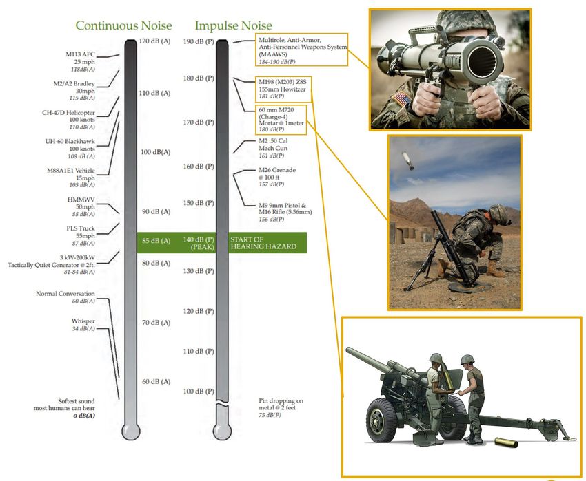
Table 34. Historical Military Weapon Noise Levels [24] . . . . . . . . . . . . . . . . . . . . . . . . . 66
Table 35. Table of Assumptions for Cost Reduction . . . . . . . . . . . . . . . . . . . . . . . . . . . . 67
Table 36. Development Costs for Past Tactical Missiles [15] . . . . . . . . . . . . . . . . . . . . . . . 67
Table 37. ISLAND compliance with the AIAA RFP requirements . . . . . . . . . . . . . . . . . . . . 69
v
Introduction

1     Introduction

1.1     Project Introduction

This report details the final missile design of the Georgia Institute of Technology’s Missile Design team for the 2020-

2021 American Institute of Aeronautics and Astronautics (AIAA) Graduate Team Missile Systems Design Competi-

tion. Each year, AIAA hosts an intercollegiate Missile Systems Design Competition with a Request for Proposal (RFP)

for a missile system that meets design requirements and has real-life applicability. For the 2020-2021 competition,

the RFP calls for a shoulder-launched, anti-UAV missile system, capable of targeting, tracking, and destroying Type

1 and Type 2 UAVs. This report provides a detailed description and discussion of the design environment, the design

process, and the final design for the ISLAND Missile.

1.2     Background and Existing Systems

As technology continues to advance, its accessibility in the commercial and military markets, both domestically and

globally, continues to increase. One technology advancement to highlight is that of drones and other unmanned aerial

vehicles (UAVs) in civilian, commercial, and military applications. Gaining popularity because of their low cost and

versatility, both the commercial and military drone markets are expanding at a rapid rate [1]. As seen in Figure 1, there

is a projected two-fold increase in the military spending on drones from 2018 to 2025. With the proliferation of these

systems, however, comes security concerns in terms of air space security and defense.

                                  Figure 1: Military UAV Market Projections [1]

                                                           1
1.2   Background and Existing Systems

      By definition, UAVs are considered to be any “powered, aerial vehicle that does not carry a human operator,

uses aerodynamic forces to provide vehicle lift, can fly autonomously or be piloted remotely, can be expendable or

recoverable, and can carry a lethal or non-lethal payload” [2]. As seen in Figure 2, UAVs are classified by their size,

range, and speed. Type 1, 2, and 3 UAVs are typically smaller models with shorter ranges, can be easily acquired, and

are available at low costs. Types 4 and 5 UAVs are less widespread, more susceptible to anti-aircraft weapons, similar

in size to manned aircraft, and are capable of larger payloads and greater ranges.

      The primary counter-UAV (c-UAV) capabilities, currently available in the U.S., are advanced air and missile de-

fense systems. These systems are designed to protect against conventional attack aircraft, bombers, and ballistic

missiles. Thus, current U.S. c-UAV capabilities are behind the curve, specifically in countering Type 1 and Type 2
                   12/7/2020                                                                Unmanned Aircraft System (UAS) Basics – Missile Defense Advocacy Alliance
low cost, small size, UAVs [3]. This gap in defensive capabilities for Type 1 and 2 UAVs is the motivation behind the
                                                                                                                                                                        Menu
design of this shoulder-launched, anti-UAV system.

                                                      Figure 2: Current US UAV Defense Capabilities [4]
                   https://missiledefenseadvocacy.org/missile-threat-and-proliferation/missile-basics/unmanned-aircraft-systems-uas/                                           4/9

      A shoulder-launched system allows for portability, providing a layer of defense to U.S. troops operating outside

the protective range of advanced air and missile defense systems. The shoulder-launch system also reduces cost

by decoupling the system from a vehicle or installation for operation. Low cost is an important feature to counter

inexpensive commercially available drones.

      Current c-UAV technologies exist in the form of current missiles, nets, directed energy, and cyber-takeovers. A

brief summary of these technologies advantages and disadvantages can be seen below in Table 1.

                                                                                                                     2
1.3 Target Characterization
Table 1: Pre-existing c-UAV Systems Advantages and Disadvantages
Advantage Disadvantage
Current Missiles Proven against larger targets Over-engineered
Net Entanglement Low Cost Slow, Low Accuracy
Directed Energy Effective against swarms Large battery capacity needed
Cyber Takeover Low recurring cost Not effective against autonomous vehicles
1.3 Target Characterization
Type 1 and 2 UAVs are small aerial systems with minimal weight and structure, typically with no hardening or armor,
and with exposed and vulnerable propulsion and flight sensor components [5]. While these characteristics make the
target more susceptible to damage, Type 1 and 2 UAVs are highly maneuverable, with vertical flight drones capable of
extreme changes in altitude. Characteristics of Type 1 and 2 UAVs can be seen in Table 2, with examples depicted in
Figure 3 and Figure 4.
Table 2: Type 1 and 2 UAV Characterization [5]
Max Operating Max Airspeed Max
Category Size MGTW (lbs)
Altitude (ft) (knots) Maneuverability (g)
Type 1 Small 0-20Requirements
Figure 4: Medium UAV’s [5]
2 Requirements
In the Systems Engineering V-model, the step following market analysis is requirement definition and concept of
operations development [6]. This section will outline the team’s interpretation of the explicit requirements, the derived
requirements, and the proposed concept of operations for the ISLAND missile.
2.1 Explicit Requirements
The request for proposal, supplied by AIAA, outlines key requirements about the missile system performance, opera-
tions, and launch crew safety, as well as information on entry into service dates and production run estimates [7].
In terms of performance requirements, the missile system shall have a threshold range of 3.0 nautical miles and
an objective range of 3.5 nautical miles. It shall have a threshold service ceiling of 3,000 ft above ground level and
an objective service ceiling of 5,000 ft above ground level. The missile system, which includes one missile and one
launcher, shall weigh no more than 40 pounds. Ten missiles and one launcher shall weigh no more than 125 pounds,
split across three personnel, with each carrying no more than 50 pounds.
In terms of operations requirements, the system shall be capable of being used in a raid scenario where ten evenly
spaced UAVs must be detected, acquired, targeted, and engaged over a time period of one hour. The design and
development of the missile will begin in October 2022 and the initial operational capability (IOC) shall occur no later
than December 2027. For production, a 10 year run with 200 missiles and 20 launchers per year is assumed. Fifteen
additional missiles will be produced for developmental testing.
In terms of safety requirements, the system shall be able to be safely stored, transported and handled for ten years
without maintenance. Furthermore, the launch acceleration shall be no more than 2g’s, the warhead shall not be armed
within 200 feet of the launch site, and the decibel noise level shall not exceed 120dB(A) within 100 ft of the launch
location.
42.2 Derived Requirements
A summary of the explicit requirements can be found in Table 3, below.
Table 3: Explicit Requirements for ISLAND
Threshold Objective
Range (nmi) 3.0 3.5
Service Ceiling (ft) 3000 5000
40 lb. for 1 missile & 1 launcher
Weight
125 lb. for 10 missiles & 1 launcher
Lifetime 10 years without maintenance
Launch acceleration < 2g’s
Safety Noise limit within 100 ft < 120dBA
Warhead arming distance > 200 ft
200 missiles & 20 launchers per year for 10 years
Production Run
+15 missiles for development testing
Development: October 2022
Entry Into Service
IOC: December 2027
2.2 Derived Requirements
Additional requirements must be derived in order to complete a successful missile design and to satisfy the explicit
requirements of the RFP. The derived requirements are grouped into the same three areas as the explicit requirements.
In terms of the derived performance requirements, the propulsion system shall be properly sized in order to meet
the range and altitude requirements. The aerodynamics of the missile must provide sufficient lift and maneuverability
performance to complete the mission. To successfully perform endgame maneuvers, the missile shall have about 3
times the maneuverability of its target [8]. Type 2 UAVs have a maneuverability no more than 2g’s, thus the missile
must have 6g’s of maneuverability in the endgame. Lastly, the missile must have enough energy to execute endgame
maneuvers. As a first order estimate, the missile shall have twice the specific energy as the target [9]. Assuming a
Type 2 UAV traveling at 200 knots, the missile would need to be traveling at 283 knots in the endgame to meet this
requirement.
In terms of the derived operations requirements, an operations model shall be developed to test the missile system
against the raid scenario. Specifically, a reloading mechanism as well as specifics for powering the detection and
tracking hardware shall be outlined. Because of the unique target, the missile seeker system shall be capable of
detecting and targeting systems that have reduced visual, radar, and/or heat signatures. Additionally, the missile shall
have a control system that is capable of successfully engaging UAVs that are highly maneuverable. Finally, the payload
system must be capable of destroying or disabling the target and if it is determined that the payload is interchangeable,
a robust payload exchange system must be designed.
Finally, in terms of the derived safety requirements, a warhead arming system must be implemented. Next, a “soft”
52.3 Concept of Operation
launch configuration shall be designed to limit the launch acceleration. Finally, additional sound mitigation must be
implemented to meet the sound limits. Many of the configurations to reduce acceleration will assist in reducing noise,
therefore these two safety requirements are highly coupled and sensitive to the final configuration.
A summary of the derived requirements can be found in Table 4.
Table 4: Derived Requirements for ISLAND
Missile shall have a properly sized propulsion system and aerodynamic surfaces
Performance Missile propulsion system shall be storable without maintenance
Requirements Missile shall weigh less than 9.4 lbs, launcher shall weigh less than 30.6
Missile shall have enough energy to engage the target in the endgame
Missile shall travel at 283 knots and have 6g’s of maneuverability in the endgame
A robust reload procedure must be designed
Operations
Missile seeker and control configuration must be compatible with target type
Requirements
If needed, a robust payload exchange system must be designed
A smart arming system must be included
Safety
A soft launch configuration is required to limit launch acceleration
Requirements
Sound mitigation must be considered
2.3 Concept of Operation
The ISLAND system will be deployed in a variety of situations and environments, both domestically and interna-
tionally. ISLAND can be used to protect government installations, like military bases, or can be used abroad in an
anti-aircraft artillery role in the field. The United States Marine Core 2nd Low Altitude Air Defense (LAAD) unit
could be a potential user of the ISLAND system [10]. The team will consist of a gunner, a spotter, and a communica-
tions officer. The gunner will be responsible for carrying the launcher with additional missile munitions. The spotter
will be responsible for additional missile munitions, targeting optics, as well as providing team security. The com-
munications officer will carry communication systems to interface with command and control as well as additional
missile munitions. The communications officer will relay intelligence to the team regarding potential UAVs threats
and be responsible for communicating mission operating procedure and rules of engagement (ROE) against identified
threats.
In its deployment, the ISLAND missile system will depend on communications with local command and control
through defined operating areas to alert the team to threats, friendly assets, and non-combatants. Initial threat detection
will likely occur from locally deployed radar assets, visually identified by combat units, or through local intelligence
assets.
The ISLAND concept of operations (CONOPS) is shown in Figure 5. First, the potential threat is detected and
identified. If it is determined that the threat can be engaged per the ROE, the user will launch the missile. The missile
6Configuration Analysis
will accelerate and track the target while gaining an advantageous position to initiate endgame maneuvers to destroy
or disable the target. For one hour, the user will have to reload, detect the next target and launch the missile within six
minutes, to successfully eliminate the UAV raid.
Figure 5: Concept of Operation for ISLAND
3 Configuration Analysis
With the requirements defined, a high level configuration analysis can begin. The configuration analysis is performed
by dividing the missile into subsystems and investigating currently deployed systems. The configuration analysis used
three weapons systems to develop alternatives for the launch system: the Raytheon Coyote Block 1 cUAS, which
uses mechanical or compressed gas to launch, the Javelin, which uses an integrated launch and flight motor, and the
Raytheon Stinger, which uses an ejectable rocket motor at launch [11][12]. The purpose of this exercise is to consider
many different alternatives, no matter how unconventional, to keep the design space open. The initial Morph Matrix
is shown in Figure 6.
7Configuration Analysis
Figure 6: Initial Morphological Matrix
The initial Morph Matrix has 18.6 million combinations. It would be infeasible to conduct a study on every
combination. Therefore, configuration down selection must occur to simplify the problem. Reasons for down selection
are described below and the down selected Morphological Matrix is shown in Figure 7.
• Infrared and laser designation seekers are eliminated because they are ineffective against small targets and targets
that do not emit a heat signature. Active radar is eliminated due to cost.
• The high fineness and faceted nose types are eliminated due to incompatibility with the seeker. The finesse and
bluntness parameters can be explored using continuous variables.
• Net and kinetic payloads are eliminated due to ineffectiveness against Type 1 and 2 UAVs.
• Wing control is eliminated due to packaging concerns and the mission type, while thrust vectoring control is
eliminated due to cost and over-complexity.
• Flap based control surfaces are eliminated due to cost and over-complexity.
• Folded control surfaces are selected due to simplicity.
• Bank-to-turn and rolling airframe maneuvers are eliminated due to over-complexity.
• Liquid and gas turbine propulsion systems are eliminated due to inability to meet 10 year storage without
maintenance requirement.
8Configuration Analysis
• Mechanical launch is eliminated because of shoulder launched integration issues.
• Steel and Aluminum alloys are selected over exotic materials to minimize the cost.
Figure 7: Down selected Morphological Matrix
Not every configuration could be eliminated, instead some subsystems required further trade studies and technical
analysis. These subsystems are placed into a Trade-Study Morph Matrix, shown below in Figure 8. There are 24
combinations and the final down selections will be made using the design environment.
Figure 8: Trade-Study Morphological Matrix
9Approach
4 Approach
There is a need to size the missile and to perform trade studies on the configurations outlined in the Trade-Study Morph
Matrix above. To fulfill these needs, a missile design environment is developed. A Design Structure Matrix (DSM)
for the environment is shown in Figure 9. Along the diagonal, in the gold, are the disciplines. In the upper triangle,
there are blue boxes which represent outputs that are fed forward. In the bottom triangle, there are blue boxes which
represent overall environment outputs or outputs that are fed backward.
Figure 9: Design Structure Matrix
The following sections detail the technical approach and physics behind each discipline in the missile design
environment.
4.1 Geometry
The missile architecture is split into a four groups: control surfaces, boattail, body, and nose. Each of these groups
is assigned two or more continuous variables. The control surfaces parameters include the number of surfaces and
several geometric parameters defining the airfoil sizing. The geometric parameters include root chord, taper ratio,
aspect ratio, leading edge thickness angle, leading edge sweep angle, and location of max thickness.
104.2 Weights, Structures, and Cost
Figure 10: Geometry Variables
Many of the variables in the figure above are inputs into the overall environment. The body fineness ratio, nozzle
diameter and body diameter are calculated using the results from the other disciplines.
4.2 Weights, Structures, and Cost
In this section, the methodology for calculating the missile weight, structural thickness and cost is outlined.
4.2.1 Weight Analysis
Launch weight is a critical factor that is input into the trajectory design environment. In the conceptual design stage,
the launch weight is derived from published correlations. It is assumed that all subsystem weights account for their
respective airframe structure. The volume of the guidance, navigation, and control (GNC) system is estimated based
on a correlation relating design range, R, to GNC volume. Then, the mass is derived using the GNC volume [13]. The
correlations are shown below in Equation (1) and (2).
VGNC = 0.0038R1.38 (1)
0.69
mGNC = 78VGNC (2)
The GNC weight includes “all of the mechanical and electronic equipment necessary to guide the missile to the
target.” This includes the seeker and the control surface actuators as well as the body tube [13]. The correlation was
114.2 Weights, Structures, and Cost
developed in the year 1986 and it is reasonable to assume that circuit board technology has advanced and electronics
have become lighter. Thus, a 0.7 factor is applied to the calculated GNC weight.
The volume of the warhead is also determined from a published correlation relating mass of the warhead to the
volume [13]. This mass value is a continuous variable and can be changed depending on miss distance performance.
The correlation is shown below in Equation (3).
Vwarhead = (mwarhead /109.5)(1/0.83) (3)
The propulsion weight is also determined from a series of empirical correlations to estimate the weight of the
igniter, nozzle, and insulation [14]. The casing weight and the propellant weight are estimated using the definition of
mass: density times volume. The equations for propulsion mass are shown in Equation (4) to (9).
migniter = 0.1502Vc0.571 (4)
mnozzle = 0.6066m0.6543
propellant (5)
minsulation = 1.7 ∗ 10−7 m−1.33 0.965
propellant · tburn (L/D)
0.144 2.69
Awall (6)
m propellant = ρ propellant Vpropellant (7)
mcasing = ρcasingVcasing (8)
m propulsion = migniter + mnozzle + minsulation + m propellant + mcasing (9)
The control surface mass is estimated by calculating the volume, assuming a constant thickness surface. The mass
is then found by definition. The relationships are shown in Equation (10) and (11).
msur f aces = Vsur f aces ρsur f ace (10)
Vsur f aces = nsur f aces Ssur f acetsur f ace (11)
Thus the mass of the entire missile is the sum of each subsystem, as shown in Equation (12).
mmissile = ∑ msubsystems = m propulsion + mGNC + msur f aces + mwarhead (12)
The length of the missile can be found using the volume of the subsystem, and the diameter of the missile, which is
defined as the casing diameter plus twice the insulation thickness. This is shown below in Equation (13) and Equation
124.2 Weights, Structures, and Cost
(14).
dmissile = dcasing + 2tinsulation (13)
Vsubsystem
Lmissile = ∑ (14)
π(dmissile /2)2 )
4.2.2 Structural Analysis
To complete the structural analysis of the missile at this conceptual design phase, forces acting on the missile will be
assumed as shown in the simplified free body diagram shown below in Figure 11.
Figure 11: Free Body Diagram for Structural Analysis
The forces include axial forces of thrust and drag, aerodynamic lift forces from maneuvers, missile weight, and
internal motor pressure. These values will be output from the final trajectory analysis for a given missile DoE case.
From the forces acting on the missile, the structural thickness can be calculated for the motor casing and the structural
airframe. In calculating the thickness, six load conditions are evaluated. First is a minimum gauge thickness for
manufacturing as there is a minimum strength that will be required to resist the force of the tooling and fixtures. Next,
buckling conditions will need to be evaluated from the bending moment due to maneuvers and the axial loading from
thrust and drag. Following buckling, the thickness will need to be evaluated in yielding from the maneuver and axial
loading. For this conceptual design phase, the values considered will be the maximum seen during the design mission
profile. Finally, the thickness for the motor casing will be calculated using the peak internal motor pressure from the
propulsion simulation. The thickness calculations are shown below in Equations 15 to 20.
tm f g = 0.7d[[pext /E]lmissile /d]0.4 (15)
tthrust = T /2πσ r2 (16)
tbuckling,bending = 2.9rσ /E (17)
134.2 Weights, Structures, and Cost
tbending = M/πσ r2 (18)
tbuckling,compression = 4.0rσ /E (19)
t pressure = pint r/σ (20)
After the thickness calculations are completed for each of the previous conditions, a root sum of squares (RSS)
approach will be used with an appropriate factor of safety (FOS) to arrive at a material thickness value.
q
toverall = FOS tm2 f g + tbuckling,bending
2 2
+ tbucking,compression 2
+ tthrust 2
+ tbending 2
+ t pressure (21)
4.2.3 Factor of Safety Calculation
The FOS used in the material thickness calculations will be based on published values such as those various military
standards. Equation 21 is used for the calculating the thickness of the motor and airframe, and a FOS of 1.50 will be
used on the applied loads and on the final thickness [15].
4.2.4 Material Selection
In an effort to reduce manufacturing costs, the airframe will be made from seamless drawn aluminum tubing with
welded bulkheads made from machined billet aluminum. The nose cone and control surfaces will be machined from
solid billet aluminum. If the production scale and strength margins exist, the use of aluminum castings for the nose
cone and internal bulkheads can be considered. For the motor casing, alloy steel was qualitatively determined to be
the best option, given the cost constraints and the motor’s operating conditions. 4130 alloy steel will be used in the
motor casing with the main body machined from seamless drawn tubing. The casing will be welded to the forward
dome and aft nozzle sections, both machined from billet 4130 steel alloy. 4130 steel alloy is used for its acceptable
strength attributes at the high motor operating temperature and its resistance to buckling during flight loads. 4130 steel
also has superior qualities for machining and welding which will reduce cost and development time associated with
the development of the missile for production. Material properties are detailed in Table 5.
Table 5: Material Proprieties for Structural Analysis
Material Density (lb/inˆ3) Yield Strength (psi) Ultimate Strength (psi) Modulus of Elasticity (ksi)
Aluminum 2219 0.103 42,100 58,000 10,600
Steel 4130 0.2819 63,100 97,200 29,700
144.3 Propulsion
4.2.5 Cost and Manufacturing
Cost estimates for the ISLAND system are estimated from correlations published in Fleeman, which are then adjusted
with additional factors based on manufacturing difficulty and technology maturity. Two cost numbers are derived from
the correlations, the first being cost for the system design and development (SDD). This correlation is based on the
time duration of 21 previous missile development programs and is show in Equation (22) [15].
CSDD = 20(106 )tSDD
1.9
(22)
Where tSDD is the program time in years and the result is in 1999 USD. Following the cost estimate for the design
and development, a correlation is used to determine the individual missile unit cost for the ISLAND program. This
correlation is based on a regression to the unit production cost of the 1000th missile from current and historical
programs based on the launch weight of the missile. This regression is shown in Equation (23) [15].
C1000 = 6100WL0.758 (23)
A summary of the discipline inputs, outputs, and assumptions are shown in Table 6.
Table 6: Table of Inputs, Outputs and Assumptions for Weight, Structures and Cost Module
Inputs Outputs Assumptions
Range Missile Mass 0.7 Factor on GNC Weight
Warhead Mass Missile Length 1.50 Ultimate Factor of Safety
Missile Diameter Unit Cost 1.15 Yielding Factor of Safety
Propulsion Mass Development Cost
Structure Thickness
It is decided that the structural thickness is not an important metric during sizing and trade studies. Thus, the
structures will be evaluated only for the final design.
4.3 Propulsion
The propulsion system had to be designed to meet multiple requirements, including the launch acceleration, launch
noise, weight, and user safety requirements. In the configuration analysis above, a solid rocket motor was selected as
the primary propulsion system type and its design process will be discussed in the upcoming sections.
154.3 Propulsion
4.3.1 Solid Rocket Motors
Solid rocket motors are commonly used in air-to-ground, ground-to-air, and booster rockets, due to their simplicity
and stability in long term storage. To model the solid rocket motor (SRM) for ISLAND, an internal ASDL tool called
Solid Motor Development Code (SMAC), was used [16]. SMAC’s current capabilities allow users to vary multiple
design, geometry, and propellant variables to output SRM specifications such as: thrust and pressure curves, motor
dimensions, and system weight. These outputs provide the necessary information for trajectory to conduct its mission
and to determine whether the safety requirements are met.
SMAC works by first defining the SRM geometry and then feeding the results into a geometric burn simulation.
The geometry module uses an edge finding algorithm to converge on a nozzle geometry as well as a propellant geom-
etry. The burn simulator models the motor burn via a unsteady lumped parameter burn algorithm [16]. An example of
the burn simulation is shown in Figure 12.
Figure 12: Example of a SMAC’s burn simulation [16]
In order to evaluate some of the alternatives in the Trade Study Morph Matrix, SMAC is modified to solve for the
characteristics of a two stage motor, that shares a common nozzle for both stages.
For solid rocket motors, the grain geometry is the driving factor for motor cost and performance. BATES grains,
or tubular grains, have progressive burn times, where star grains have more steady burn times, and multi-fin grains
have large thrust profiles very early in the burn, but quickly reduce to low thrust for the remainder of the burn. The
difference between the grain geometries is shown in Figure 13.
164.3 Propulsion
Figure 13: Solid Rocket Motor Grains and their Thrust Profiles [17]
Due to the short design range, low launch acceleration and low noise requirement, a BATES grain was selected
for further analysis, with possible implementation of an end-burn geometry to boost the missile speed and increase
maneuverability in the endgame. A BATES grain is also the cheapest and simplest to manufacture, reducing the unit
cost.
A standard commercially available Ammonium Perchlorate Composite Propellant (APCP) is selected for the pre-
liminary design. Its characteristics were experimentally determined by the Georgia Tech Experimental Rocketry Club
and the results are shown in Table 7.
Table 7: Propellant Characteristics used in ISLAND Preliminary Design
Burn Rate Pressure Propellant Density Characteristic
Coefficient (psi) Exponent (psi) (slug/inˆ3) Velocity
0.027 0.3 0.00176 4890
A summary of the discipline inputs, outputs, and assumptions are shown in Table 8.
Table 8: Table of Inputs, Outputs and Assumptions for Propulsion Module
Inputs Outputs Assumptions
MEOP Thrust Curve Grain Type: BATES
Grain Diameter M-dot Curve Propellant Type: APCP with characteristics in Table 7
Grain Inner Diameter Nozzle Geometry Density of Motor Casing: 0.284 lb/inˆ3 (4130 Steel)
Grain Fineness Ratio Insulation Geometry Density of Insulation: 0.0311 lb/inˆ3 (EPDM Rubber)
Casing Geometry
Subsystem Mass
174.4 Aerodynamics
4.4 Aerodynamics
The purpose of the aerodynamics discipline is to link missile geometry and flight conditions to the aerodynamic forces
produced by the missile. This discipline environment needed to be capable of producing lift and drag forces for each
time step when interfaced with the trajectory code. In addition, the aerodynamics code needed to be able to size
and verify stability and maneuverability requirements for individual on-design and off-design scenarios. The chosen
methodology that fits these calculation requirements is the conceptual design aerodynamics approach described in
Fleeman’s Tactical Missile Design book [15]. The aerodynamic predictions generated with this code are based on flight
conditions, geometry, historical regressions, and other derivations as described in Fleeman. The process walks through
the build up of axial and normal force coefficient calculations for the nose, body, boat tail, and any additional surfaces.
One assumption made during this build up process is that the aerodynamic axial force coefficient is dominated by the
zero-lift drag coefficient, so we assume that these are equal, as shown in Equation (24). A notional build up of the
normal force coefficient is shown in Equation (25). After these force coefficients are determined, basic transformations
can be applied to adjust axial and normal into lift and drag, as shown in Equations (26) and (27) respectively. The
following sub-sections will breakdown the individual missile contributions for Equations (24) and (25).
CA = CD0 = (CD0 )Body + (CD0 )Canard + (CD0 )Tail (24)
CN = (CN )Body + (CN )Canard + (CN )Tail (25)
CL = CN cosα −CD0 sinα (26)
CD = CN sinα −CD0 cosα (27)
4.4.1 Missile Body
The drag forces on the missile body are further broken down into the friction drag induced on the missile skin, the
wake drag produced by the missile base, and the wave drag at the missile nose during supersonic flight. The friction
drag is directly related to the length of the missile and the flight conditions. The wake drag is highly dependent on
whether or not the motor is firing. If the motor is firing then there is less aft area to create a wake. To further reduce
this aft area, a boat tail is often added. The wave drag is coupled with the nose fineness, so if the mission takes place
in the supersonic regime, then the drag could be reduced with a longer nose length. Equations (28) through (33) show
in detail the equations used to calculate the drag on the body.
184.4 Aerodynamics
(CD0 )Body = (CD0 )Body,Friction + (CD0 )Base + (CD0 )Body,Wave (28)
(CD0 )Body,Friction = 0.053(l/d)[M/(ql)]0.2 (29)
0.25/M M>1
(CD0 )Base,Coast = (30)
0.12 + 0.13M 2 M1
(CD0 )Base,Powered = (31)
(1 − Ae /SRe f )(0.12 + 0.13M 2 ) M1
(CD0 )Body,Wave = (32)
0 M4.4 Aerodynamics
4.4.2 Missile Control Surfaces
The drag forces on the missile control surfaces are further broken down into the friction and wave drag similar to the
body. It was assumed that the deflection of the control surfaces was zero throughout our sizing process and instead the
entire missile pitches to meet force requirements. This assumption was made because the trajectory code would have
needed to include a more advanced control system to leverage the surface deflection. The equations used to compute
the drag for the missile surfaces are shown in Equations (37) through (39).
(CD0 )W,Friction = nW [0.0133/(qcmac )0.2 ](2SW /SRe f ) (37)
γ 1
[(γ+1)MΛLE ] γ−1
2nW
(CD0 )W,Wave = [ (γM 2 ) ]{{ 2 } { [2γM2(γ+1)
−(γ−1)]
} γ−1 − 1}sin2 δLE cosΛLE tSmac b
Re f
MΛLE = McosΛLE > 1 (38)
LE ΛLE
(CD0 )Wing = (CD0 )W,Wave + (CD0 )W,Friction (39)
Next, the normal force coefficients for any surfaces on the missile need to be calculated. Linear wing theory and
Newtonian impact theory are applied to low aspect ratio surfaces AR ≤ 3. These relationships are summarized in
Equation (40), where α 0 = α + δ , where δ is the canard deflection. For preliminary design, δ is always assumed to be
0.
|(CN )Wing | = [4|sinα 0 cosα 0 |/(M 2 − 1)1/2 + 2sin2 α 0 ] SSReW f 8
M > {1 + [ (πAR) ]2 }1/2
(40)
|(CN )Wing | = [(πAR/2)|sinα 0 cosα 0 | + 2sin2 α 0 ] SSReW f 8
M < {1 + [ (πAR) ]2 }1/2
Equation (41) shows the equation to find the center-of-pressure location for a surface as a function of Mach number
and aspect ratio. This will be used with stability.
[AR(M 2 −1)1/2 −0.67]
xAC [2AR(M 2 −1)1/2 −1]
M>2
( )Wing = (41)
cMAC 0.25 M≈0
Equation (42) shows the equation to find the normal force curve slope due to angle of attack for the missile control
surfaces. This will also be used with stability.
4 8 2
√ M 2 > 1 + ( πAR )
(CNα )Wing = M 2 −1 (42)
8 2
π AR
2 M 2 < 1 + ( πAR )
204.5 Trajectory
4.4.3 Missile Stability
To calculate stability requirements, Equation (43) was rearranged to instead solve for the canard center of pressure
location. This leaves canard chord and tail chord as free variables. The tail location is fixed to the base of the body
tube for all configurations.
(ST )Req
SRe f = {(CNα )B [xCG −(x
d
CP )B ]
+ (CNα )W { [xCG −(x
d
CP )W ]
}/{{ [(xCP )Td −xCG ] SSReW f }(CNα )T } (43)
The implementation of the aerodynamics environment was verified against an air-to-air example sizing case in
Fleeman [15]. The results of the verification are shown in Table 9. The majority of this error is due to the truncation
and rounding of arithmetic presented in the text.
Table 9: Aerodynamics Environment Verification Results
Value Fleeman Aerodynamics Environment % Error
Missile Normal Force Coefficient 11.1 11.048 0.47%
Missile Drag Coefficient 1.06 1.053 0.66%
A summary of the discipline inputs, outputs, and assumptions are shown in Table 10. Fleeman’s estimate for
wave drag produced by a surface is based on a double wedge airfoil defined by a leading edge thickness angle and
location of maximum thickness. From initial trajectory analysis, it was assumed that the missile would spend time in
the transonic regime and thus double wedge airfoils are applicable to the mission and the provided equations can be
used. It was assumed that the maximum thickness would be located at the quarter chord and the leading edge thickness
angle would be driven by a maximum thickness constraint.
Table 10: Table of Inputs, Outputs and Assumptions for Aerodynamics Module
Inputs Outputs Assumptions
Surface Geometry Lift Airfoil Type: Double Wedge
Body Geometry Drag Location of Max Thickness: 0.25c
Boat-tail Geometry Max Maneuverability 4 Surfaces per Tail/Canard
Nose Geometry Stability Information
2D sketch
4.5 Trajectory
The purpose of the trajectory discipline is to carry the missile through its design mission and to determine whether
or not the missile hits the target and meets additional requirements. To carry out its goal, the trajectory environment
214.5 Trajectory
uses results from the weight, aerodynamics, and propulsion environments. The following subsections will outline the
equations of motion, trajectory propagation, trajectory guidance, and the sensor modeling.
4.5.1 Equations of Motion
The equations of motion for the missile and the target model the kinematics of the system. A three degree of freedom
(3-DOF) system was implemented because the requirements only specify a downrange objective. A 3-DOF system is
preferred over a full 6-DOF system because of the reduction in run time and complexity. Furthermore, control design
is not the goal of the preliminary trajectory environment so a 6-DOF system is not needed. A flat earth assumption is
made because the objective range is small, only 3.5 nautical miles.
Because a 3-DOF system is chosen, only movement in the horizontal, vertical and pitch directions is modeled. The
state of the system is shown below in Equation (44).
ẋ vx
ẏ v
y
v˙x Fx /m
= (44)
v˙y Fy /m
α̇ q
ṁ ṁ
The missile experiences lift and drag forces that are parallel and perpendicular, respectively, to the wind direction.
Thrust is always applied parallel to the roll axis since thrust vectoring is not used. A free body diagram is developed
for the missile and it is shown in Figure 14.
Figure 14: Free Body Diagram of the 3DOF Missile System
224.5 Trajectory
Using this diagram, the equations for the X and Y direction forces are derived. Equations (45) through (47) show
equations for the X and Y direction forces as well important aerodynamic variables like flight path angle and pitch
angle.
Fx = T cos(θ ) − Dcos(γ) − Lsin(γ) (45)
Fy = T sin(θ ) − Dsin(γ) + Lcos(γ) −W (46)
vy
γ=p (47)
vx + vy 2
2
θ = γ +α (48)
The thrust and mass flow are found by interpolating the thrust and mass flow curves output by the propulsion
environment. Aerodynamic forces were found by calling the aerodynamics module for each time step. Information
such as angle of attack, Mach number, dynamic pressure, and whether or not the missile was powered was input into
the module. The following equations were used to model the standard atmosphere:
T = T0 + ah (49)
T ( −g0 )
P = P0 ( ) aR (50)
T0
T −g0 +aR
ρ = ρ0 ( )( aR ) (51)
T0
In the equations above, a represents the slope of temperature with respect to altitude, h represents altitude, R
represents the ideal gas constant, g0 represents the sea level gravitational acceleration and T0 , P0 and ρ0 represent the
sea level standard temperature, pressure and density.
For preliminary sizing, the target is modeled as a hovering target at 3.5 nautical miles, 5,000 ft. Capability does
exist to test a moving and accelerating target during detailed design.
4.5.2 Trajectory Propagation
The purpose of trajectory propagation is to move the missile or target state one time step. The environment implements
the fourth order Runge Kutta method (RK4) to propagate the target and missile [18]. Because the equations of motion
234.5 Trajectory
are of the form ẋ = f (xi ,ti ), Equations (52) through (56) can be used to solve for the state in the next time step.
k1 = f (xi ,ti ) (52)
h h
k2 = f (xi + k1 ,ti + ) (53)
2 2
h h
k3 = f (xi + k2 ,ti + ) (54)
2 2
k4 = f (xi + k3 ,ti + h) (55)
h
xi+1 = xi + (k1 + 2k2 + 2k3 + k4 ) (56)
6
The time step, h, is held constant at 0.1 seconds for a majority of the flight. When the missile travels within 300 ft
of the target, the time step decreases to 0.01 seconds. This selection of time steps provides good run time performance
while not compromising endgame fidelity.
4.5.3 Trajectory Guidance
The purpose of the trajectory guidance is to control the vehicle by changing the pitch rate, q. For preliminary design,
the pitch rate is assumed to have no lag. The sizing mission is either the objective mission or the threshold mission, as
outlined in the requirements.
The guidance is broken down into three phases, launch, boost and tracking, each with its own control logic. The
control logic uses noise measurements from the GPS/INS and the seeker. These measurements must be filtered using
a Kalman filter before being used in the control algorithm.
Launch Phase
The launch phase lasts only 0.5 seconds, enough time for the missile to travel approximately 100 feet. The purpose
of this phase is to gain speed as well as to travel directly away from the soldier, to minimize the noise when the flight
motor ignites. During this phase, the missile guidance attempts to target a flight path angle, γ0 of 45 degrees. This
flight path angle will ensure a positive rate of climb during the launch phase and is similar to that of the Stinger missile
[12].
A simple proportional controller is sufficient to achieve this task. Equation (57) shows the algorithm. In the
equation below, the proportional gain, K p , was set to 0.1.
q = K p,launch (γ0 − γ) (57)
244.5 Trajectory
If a lower launch angle is chosen, K p,launch must be increased to ensure the missile does not have a negative climb
rate.
Boost Phase The purpose of the boost phase is to allow the missile to climb and gain speed. The inputs to this phase
are the flight path angle and the time of the boost phase. These inputs are optimized using Python’s Scipy Optimize
package. The angle and time are optimized for each missile design and configuration. For better performance, the
boost time is limited to 5 seconds maximum, and the angle is limited to 70 degrees. The missile guidance algorithm
attempts to target the optimized flight path angle, γopt . As above, a simple controller is sufficient to achieve this task.
Equation (58) shows the algorithm. In the equation below, the proportional gain, K p,boost , was set to 0.1.
q = K p,boost (γopt − γ) (58)
Tracking Phase
The tracking phase lasts for the rest of the flight. The purpose of this phase is to track and hit the target. During
this phase, the missile implements a proportional navigation algorithm, shown in Figure 15.
Figure 15: Diagram of proportional navigation [19]
The goal of proportional navigation is to maintain a constant line of sight (LOS) angle rate, λ˙0 = 0, between the
target and the missile [19]. This is achieved by first using the GPS/INS and seeker filtered measurements to calculate
the line of sight angle rate. A proportional integral derivative (PID) controller is used to drive this LOS angle rate to
zero. Equations (59) through (61) show this calculation and the control algorithm. The gains are determined on a trail
basis and are as follows K p,track = 5, Ki,track = 0.1 and Kd,track = 14.
254.5 Trajectory
yt − ym
λ = atan( ) (59)
xt − xm
dλ
e(t) = − λ˙0 (60)
dt
de(t)
Z
q = K p,track e(t) + Ki,track e(t)dt + Kd,track (61)
dt
A simple proportional (P) controller is insufficient to hit the target and results in very high oscillations. A proportional-
derivative (PD) controller is sufficient to hit the target but has somewhat poor accuracy. The algorithm could be
improved if a full PID controller is implemented. Care should be taken to ensure that integral gain is not too high
otherwise the trajectory will flatten out. Figure 16 shows examples of the trajectory when different control algorithms
are implemented.
Figure 16: Comparison of different controller gains
The pitch rate, q, is limited by the maximum possible acceleration that can be generated from the aerodynamic
surfaces. If the pitch rate exceeds the maximum allowable pitch rate it is updated as shown in Equation (62).
q = amax /v (62)
The different phases of the trajectory guidance, for a notional mission, are illustrated below in Figure 17.
26You can also read