Design of Smart Home Service Robot Based on ROS
←
→
Page content transcription
If your browser does not render page correctly, please read the page content below
Hindawi
Mobile Information Systems
Volume 2021, Article ID 5511546, 14 pages
https://doi.org/10.1155/2021/5511546

Research Article
Design of Smart Home Service Robot Based on ROS

          Jiansheng Peng ,1,2 Hemin Ye ,1 Qiwen He ,1 Yong Qin ,1 Zhenwu Wan ,3
          and Junxu Lu 1
          1
            Hechi University, 42 Longjiang Road, Yizhou 546300, China
          2
            School of Electronic Engineering, Guangxi Normal University, Guilin, Guangxi 541004, China
          3
            Hubei University of Education, Wuhan 430205, China

          Correspondence should be addressed to Qiwen He; saymyself2006@163.com

          Received 6 January 2021; Revised 2 March 2021; Accepted 16 June 2021; Published 28 June 2021

          Academic Editor: Hsu-Yang Kung

          Copyright © 2021 Jiansheng Peng et al. This is an open access article distributed under the Creative Commons Attribution License,
          which permits unrestricted use, distribution, and reproduction in any medium, provided the original work is properly cited.
          At present, the functions of home service robots are not perfect, and home service robot systems that can independently complete
          autonomous inspections and home services are still lacking. In response to this problem, this paper designs a smart home service
          robot system based on ROS. The system uses Raspberry Pi 3B as the main control to manage the nodes of each sensor. CC2530 sets
          up a ZigBee network to collect home environmental information and control home electrical appliances. The image information
          of the home is collected by the USB camera. The human speech is recognized by Baidu Speech Recognition API. When en-
          countering a dangerous situation, the GSM module is used to give users SMS and phone alarms. Arduino mega2560 is used as the
          bottom controller to control the movement of the service robot. The indoor environment map of the home is constructed by the
          lidar and the attitude sensor. The service robot finally designed and developed realizes the functions of wireless control of home
          appliances, voice remote control, autonomous positioning and navigation, liquefied gas leakage alarm, and human infrared
          detection alarm. Compared with the household service robots in the related literature, the household service robots developed by
          us have more complete functions. And the robot system has completed the task of combining independent patrol and home
          service well.

1. Introduction                                                         the population becoming more and more serious, the de-
                                                                        mand for smart home service robots is also increasing.
In recent years, with the development of science and tech-                  Most young workers nowadays basically go out to work
nology, various robots have appeared in people’s lives, for             during the day and only spend a short time at home. If there
example, handling robots in factories [1], medical robots in            is any dangerous situation at home, it is difficult to find out
hospitals [2], service robots in hotels [3], food delivery robots in    and take relevant measures at the first time. In recent years,
restaurants [4], and smart home service robots that reduce the          home burglaries and gas leaks have occurred frequently. In
burden on family members [5]. Among them, the smart home                order to ensure that the home is safe enough, there needs to
service robot is the closest to people’s lives and the most used.       be a “people” in the home at this time and can send alarm
    According to a recent survey by the World Health                    messages to the owner at any time when encountering
Organization, in 2015, the number of people over 60 years               danger so as to reduce the owner’s economic loss. The
old in the world reached 900 million people, and by 2050, the           “people” mentioned here are smart home service robots. In
number of people over 60 years old will reach 2 billion [6].            addition, this type of robot can help the owner do housework
More and more elderly people are unable to complete some                (such as sweeping the floor) to reduce the burden on the
tasks smoothly due to their age. At this time, they need the            owner. In addition, when the owner who works outside
assistance of smart home robots. And smart home service                 wants to have hot water to drink as soon as he returns home,
robots can be used as companion objects for the elderly so              he can send corresponding instructions to the smart home
that they will not feel lonely at home. And with the aging of           service robot in advance to turn on the electric tea kettle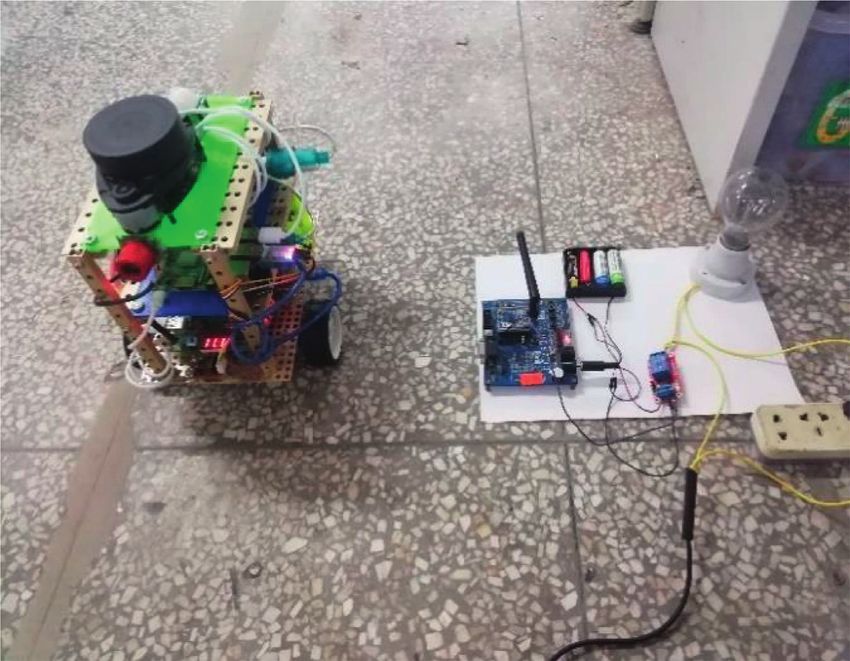
2                                                                                                    Mobile Information Systems

heating function, and the owner can drink hot water when             thereby motivating them to stay active and independent and
he returns home.                                                     improve their well-being. The goal of this work is to enable
    In summary, smart home robots can share housework                these elderly people to live independently for as long as
for people and reduce the burden on the owner and can                possible in their preferred environment by providing in-
bring a lot of convenience to people’s lives. Especially for the     formation and communication technology nursing services.
elderly, smart home service robots bring convenience to              As a service robot, the platform provides assistance to users
their lives and add a lot of fun to their lives. In addition, the    and aims to solve the early preventive and health care
danger alarm function of the smart home service robot can            problems of the aging process. The three robots mentioned
make people’s home life safer. Therefore, smart home service         above are mainly human-computer interaction functions,
robots are becoming more and more important to people’s              which are designed to bring convenience and joy to the
daily lives. However, the functions of some smart home               owner, especially for the elderly, but they are not involved in
service robots are not yet perfect, so it is necessary to re-        other functions.
search and develop smart home service robots with more                   Saunders et al. deployed a commercial autonomous
comprehensive functions.                                             robot in an ordinary suburban house. This robot describes
    The organizational structure of the rest of this article is as   teaching, learning, and robot and smart home system design
follows. Related work will be discussed in the second part.          methods as an integral unit. Experimental results show that
The third part introduces the overall design of the system in        participants think this method of robot personalization is
detail. In the fourth part, the hardware design of the motion        easy to use and can be used in real life [5]. Abdallah and
system, power supply system, wireless communication                  others used open source solutions to build a completely
system, alarm system, and autonomous navigation system is            independent intelligent assistant robot, specifically for the
introduced. In the fifth part, the software design of the             elderly to manage smart homes. The system is built around a
system is introduced, including motion system software               voice communication module based on Mycroft AI for
design, wireless communication system software design, and           communicating with sensors and smart devices. It includes
autonomous navigation software design. The sixth part gives          many software applications for recognizing faces, setting
an introduction to system debugging. The seventh part                tasks, and answering specific questions and requests. The
compares the functions and experience of the smart home              embedded system is used as the local server to manage the
service robot. The eighth part is the summary of this article.       smart home and its applications. The results show that the
                                                                     robot can perform various forms of actions to answer user
2. Related Work                                                      queries [12]. Berrezueta-Guzman et al. [13] introduced the
                                                                     design of smart home environment. In this project, the
With the development of electronic information technology            Internet of Things (IoT) paradigm is combined with the
and the improvement of people’s living standards, people are         development of robotic aids to realize a smart home envi-
increasingly yearning for the life of smart home [7]. The            ronment. In this environment, the included smart things can
concept of smart home is to integrate different services in           determine the behavior of the child in the process of doing
one home by using a common communication system [8].                 homework in real time. There is also a robotic assistant in the
Smart homes ensure economical, safe, and comfortable                 project that interacts with the child and provides necessary
home operations, including highly intelligent functions and          companionship (supervision and guidance), just like the
flexibility. In recent years, with the development of robotics        therapist would do. The purpose of this project is to create a
technology, more and more robots are used in smart homes             smart place for treatment purposes in the family to help
and become smart home service robots. These robots bring             children who suffer from ADHD and find it difficult to
people an economic, safe, comfortable, and happy family              complete their homework. The above three kinds of robots
life.                                                                can all perform voice interaction, but they all lack the
      With the gradual aging of society, the number of elderly       functions of hazard alarm and home appliance control.
people has gradually increased. When there is only one                   Literature [14] explored the possibility of integrating
elderly person at home, the mood and safety of the elderly           wireless sensor networks and service robots into smart home
are worthy of consideration. Wada K et al. invented a                applications. Service robots can be regarded as mobile nodes,
companion robot for the elderly named “Paro” [9]. “Paro” is          providing additional sensor information, improving/fixing
a robot that can imitate animals. While bringing joy to the          connectivity, and collecting information from wireless
owner, there is no need to worry that it will bite you like a        sensor nodes. The wireless sensor network can be regarded
real animal. “Schpuffy” is also a companion robot [10]. It            as an extension of the robot’s perception ability, providing
checks the owner’s schedule every morning. If it finds that           an intelligent environment for the service robot. The robot
the owner has an appointment at 8 : 30, it will wake up the          mainly realizes that the robot obtains effective information
owner in advance at 8 o’clock. If the weather is very cold, it       from the sensor network so as to control the related
will remind the owner to wear more clothes to keep warm. It          equipment. In 2018, Taiwanese researchers proposed a smart
will say goodbye to the owner when the owner leaves, and it          home control system. The system integrates the Internet of
will lock the door when the owner leaves. Literature [11] is         Things, wireless sensor networks, smart robots, and single
dedicated to the development of social robotic systems to            board computers to realize smart home applications. They
provide companionship, care, and services to the elderly             use wireless technology and automation equipment to avoid
through information and communication technology (ICT),              adding too many communication cables, making the house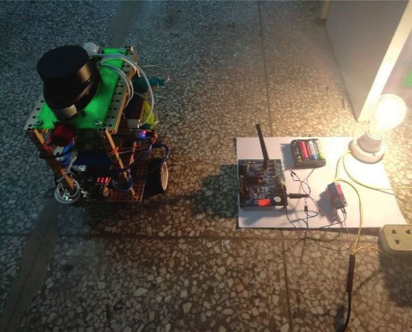
Mobile Information Systems                                                                                                    3

more intelligent, keeping indoor activities smooth and tidy.          The system framework is shown in Figure 1. The ROS-
This system brings intelligence and convenience to the            based smart home service robot system uses Raspberry Pi 3
family and makes the living environment more comfortable          as the main control core board. It consists of lidar, attitude
[15]. However, the above two types of robots do not have          sensor, USB camera, CC2530 coordinator, CC2530 terminal
functions such as human-computer interaction and voice            node, relay module, MQ-5 module, SHT temperature and
recognition.                                                      humidity module, Arduino mega2560, motor, motor drive
     The functions of the robots researched and developed in      module, human body infrared module, and GSM module.
the above literature are not very comprehensive, and it is        The ROS system is installed on the main control core board
difficult to meet people’s needs for a comfortable, conve-          to exchange information with each module to control and
nient, safe, and fun home life. And they generally lack a         run the entire system. The CC2530 coordinator and CC2530
home robot system that can independently complete the             terminal nodes construct a ZigBee network. The serial
combination of autonomous inspections and home services.          communication between the CC2530 coordinator and the
If the smart home service robot has incomplete functions          main control core board realizes information exchange. The
and cannot complete the task of combining autonomous              CC2530 terminal node drives the relay module, MQ-5
patrols and home services, this will bring a bad experience to    module, and SHT temperature and humidity module, re-
users. In order to meet people’s needs for a comfortable,         spectively. These are used to collect environmental infor-
convenient, safe, and fun home life, this paper has               mation at home and control household electrical appliances.
researched and developed a home robot system that has             Users can control the entire system by connecting the robot
more complete functions and can independently complete            through the mobile phone.
independent inspections and home services. This system is a
smart home service robot system based on ROS, which can           4. System Hardware Design
help people manage and control household appliances,
which brings convenience to people. Its voice recognition         4.1. Motion System Hardware Design
function makes the communication between the owner, and
it simple and convenient. For the elderly, this function can      4.1.1. Mobile Chassis Structure Design. The movement
make them no longer feel lonely when they are at home             method of robot movement adopts wheeled transmission
alone and at the same time increase the joy of life for the       method. The structure of the mobile chassis is shown in
elderly. It can also detect the situation at home. When there     Figure 2. The a and the b are DC geared motors. A wheel and
is a dangerous situation, it will send out an alarm to the        B wheel are used as driving wheels. The C wheel is a universal
owner, thereby reducing the owner’s economic loss and             wheel as an auxiliary wheel. This constitutes a self-balancing
playing the effect of protecting the safety of the home.           robot mobile chassis.

3. Overall System Design                                          4.1.2. Movement System Hardware Composition. The
                                                                  hardware of the robot motion system is composed of the
ROS (robot operating system) [16] is a metalevel operating        L298P Moto Shield DC motor drive expansion board, the
system suitable for robot open source. Compared with other        Arduino mega2560 development board, and the DC gear
robot operating systems, ROS mainly has the following             motor. The DC geared motor has a 13-wire AB two-phase
characteristics. (1) ROS provides a publish-subscribe com-        Hall encoder. The phase A and phase B outputs of the
munication framework for building distributed computing           encoder differ by 90°. The value read by the combination of
systems simply and quickly. (2) It provides a large number of     two-phase is 4 times the term. The motor generates 780
simulation and data visualization tool combinations to            pulses per revolution. Then, the speed n is as follows:
configure, start, self-check, debug, visualize, login, test, and
terminate system. (3) It also provides a large number of                                          N
                                                                                         n�               ,                 (1)
library files and realizes functions such as autonomous                                        4 × 780 × t
movement, operating objects, and perception of the envi-          where N is the number of pulses in time t.
ronment. (4) The support and development of ROS con-                  The system uses the external interrupt of the I/O port of
stitute a powerful ecosystem.                                     the Arduino mega2560 development board to read the
    ZigBee technology [17] is a low-rate and short-distance       encoder pulse number. The speed of the geared motor is
wireless transmission technology based on IEEE802.15.4. It        calculated by Equation (1). The controller outputs PWM
is characterized by self-organizing network, supporting a         through the driver to drive the reduction motor to rotate.
large number of network nodes, low power consumption,
low speed, low cost, safe, and reliable. ZigBee technology is
widely used in the fields of home network, medical sensors,        4.2. Power System Hardware Design. The power system
and servo execution.                                              structure is shown in Figure 3. The main power supply uses
    Arduino is an open source electronic platform [18]. It        11 V lithium battery. The secondary power supply uses 5V
has rich library resources and simple code structure, suitable    batteries. The main power supply supplies power to the gear
for completing the driving of the robot and connecting with       motor through the L298P Moto Shield DC motor drive
various electronic components to realize data collection and      expansion board. Raspberry Pi power supply needs 5 V/2A
processing.                                                       to work properly. Therefore, the CKCY buck module (which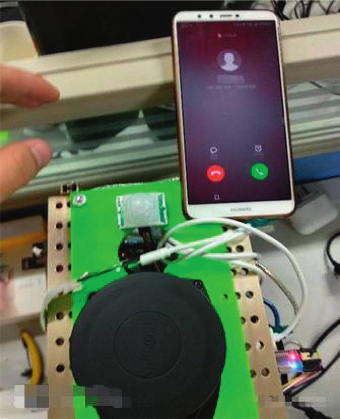
4                                                                                                                                                                        Mobile Information Systems

                                                        SHT temperature
                                                         and humidity
     MQ–5 module                                           module                                             Relay module
    CC2530 terminal                                     CC2530 terminal                                         CC2530
        node                                                 node                                            terminal node

     USB camera                                                                                                      CC2530
                                                                                                                   coordinator

                                                        Raspberry Pi 3B
                                                                                                                     Attitude
             Lidar                                                                                                    sensor
                                                                              Wi-Fi                                                                                                 Mobile
                                                                                                                                                                                   terminal

     Motor drive                                                                                                   GSM module
      module
                                                       Arduino mega2560
         Human
         infrared                                                                                                  Geared motor                                                                  Wi-Fi
         module

                                                          Figure 1: System framework diagram.

                                                                                  C

                                                   A                          a                       b                                         B

                                                   Figure 2: Structure diagram of mobile chassis.

                                                    Main power supply (11 V)                                                                                        Secondary power
                                                                                                                                                                      supply (5 V)

                                            CKCY                                                          LM2596S
    L298P moto shield DC
    motor drive expansion

                                           (5V/3 A)                                                       (5 V/1 A)
           board

                                                                                                                                            Human infrared module

                                                                                                                                                                          CC2530 terminal node
                                                                                                                       CC2530 coordinator

                                    Raspberry Pi 3B
                                                                                      Motor encoder

                                                                                                      GSM module
                                      USB camera

                                                        mage2560
                                                        Arduino

                                                                   Attitude
       Geared

                                                                    sensor
       motor

                            Lidar

                                                       Figure 3: Ower system structure diagram.
Mobile Information Systems 5
can output 5 V/3A) is used to get 5 V power supply. The VCC (5V) VCC (5 V)
lidar, USB camera, Arduino mega2560, and attitude sensor Arduino mage2560
VCC
are powered by the USB serial port of the Raspberry Pi. The Human VCC PIN 31 UTX
main power supply is reduced to 5 V through the LM2596S infrared OUT PIN 8 GSM module
buck module and supplies power to the motor encoder, GSM module GND PIN 33 URX
GND
module, CC2530 coordinator, and human body infrared
module. The CC2530 terminal node is directly powered by a
GND GND
5 V secondary battery.
Figure 4: Human body module and GSM module wiring diagram.
4.3. Wireless Communication System Hardware Design.
The coordinator and the terminal nodes constitute the
hardware component of the wireless communication sys- VCC VCC
tem. There can only be one coordinator in each network. The CC2530
DO P0_5
main functions of the coordinator are to establish a network, MQ–5 module end
assign network addresses, and maintain a binding table. The AO P0_6 node
terminal node is used for each device node of the network.
The same network can have up to 256 end nodes. The MQ-5 GND GND
module, SHT temperature and humidity module, and relay
switch are connected to the terminal node for information Figure 5: Wiring block diagram of MQ-5 module and CC2530
collection and control of household electrical appliances. terminal node.
4.4. Alarm System Hardware Design. The human body in- operation of the Arduino mega2560. The CC2530 coordi-
frared module, MQ-5 liquefied gas module, and GSM nator is mainly used to obtain data of CC2530 terminal
module constitute the hardware component of the robot nodes. Arduino mega2560 mainly obtains encoder data and
alarm system. The human body infrared module is used to human body infrared sensor data. Control motor drives and
detect whether there are someone breaks into the house controls GSM module work. The service robot software
when living outdoors. MQ-5 liquefied gas module is used to framework is shown in Figure 7.
detect whether there is a liquefied gas leak in the home. The
GSM module is used to send text messages and dial phone
calls to the residents. The wiring of human body infrared 5.2. Motion System Software Design. The robot adopts the
module, GSM module, and Arduino mage2560 is shown in incremental PID method to adjust the movement speed. The
Figure 4. The connection mode between the MQ-5 module specific steps for adjusting the movement speed are as
and the CC2530 terminal node is shown in Figure 5. follows:
(1) When the deviation value of the motor speed is
obtained, the upper computer sets the moving speed
4.5. Autonomous Navigation System Hardware Design.
of the service robot. The lower computer obtains the
The hardware components of the robot’s autonomous
speed value sent by the upper computer. The en-
navigation system are composed of lidar and attitude sen-
coder’s own encoder is used to calculate the en-
sors. The system uses lidar to detect the surrounding en-
coder’s pulse to obtain the current actual speed of the
vironment through 360° scanning and ranging and then
service robot. Finally, the system subtracts the two to
collects and processes the data. Finally, the system builds a
get the speed deviation value.
digital map of the surrounding environment. The attitude
sensor is used to obtain the data of acceleration, angular (2) This system calculates the duty cycle through the
velocity, and magnetometer. In this way, the current real- PID incremental algorithm. The system obtains the
time motion state of the robot can be solved. The wiring of latest 3 speed deviation values and then obtains the
Lidar, attitude sensor, and Raspberry Pi 3B is shown in duty cycle through the PID incremental algorithm.
Figure 6. It should be noted here that the minimum and
maximum duty cycle values need to be set to avoid
the motor rotating speed being too small or too
5. System Software Design large.
5.1. Software Overall Design. The designed smart home (3) Let the drive motor rotate to achieve speed regula-
service robot uses Raspberry Pi as the main control core. The tion. The obtained duty ratio is converted to the
system uses CC2530 coordinator to build the network and corresponding PWM output value. Let the output
CC2530 terminal nodes to form a wireless control network. PWM drive the motor speed to achieve speed reg-
The system also uses Arduino mega2560 as the slave con- ulation. The change of the motor speed will in turn
troller. The Raspberry Pi 3B mainly processes lidar data, affect the speed deviation value. The duty cycle
attitude sensor data, USB camera data, voice recognition changes as the motor speed changes. The output
API, and CC2530 coordinator data and controls the PWM value also changes accordingly. This process is6 Mobile Information Systems
GND
USB to TTL
TX adapter
RPLIDAR
Attitude sensor
RX A1USB USB USB board GND GND
serial serial serial RX TX
Lidar
VS
GND port port 1 port 2 TX RX
adapter
DTR VCC VCC
board
VS Raspberry Pi 3B
Figure 6: Wiring diagram of lidar and attitude sensor.
Lidar
Attitude Motor encoder
sensor
USB camera Motor driven
Speech Raspberry Pi 3B Arduino mega2560
recognition Human
API infrared
sensor
CC2530
coordinator
GSM module
CC2530
terminal node
Figure 7: Software block diagram.
repeated, and the final motor speed tends to the set
theoretical speed.
5.3. Software Design of Wireless Communication System.
ZigBee technology is a low-rate and short-distance wireless
transmission technology based on IEEE802.15.4. ZigBee
technology has the characteristics of self-organizing net-
work, supporting a large number of network nodes, low
power consumption, low speed, low cost, safety, and reli-
ability. ZigBee technology is widely used in the fields of
home network, medical sensors, and servo execution. The End node
robot wireless communication system uses ZigBee network
for wireless communication. The ZigBee network is com- Coordinator
posed of a coordinator and terminal nodes and uses a star Figure 8: Star network topology.
network topology as shown in Figure 8.
configure the PIN_ID and network channel consistent with
5.3.1. CC2530 Coordinator Builds ZigBee Network. In a the coordinator. After receiving the request sent by the
wireless communication system, the coordinator is equiv- coordinator, the terminal node recognizes it. After the
alent to the controller in the network. It dominates the entire recognition results completely match, the network is built.
network. From the establishment of the network to the The process for the coordinator to build a ZigBee network
processing and transmission of system data, including the is shown in Figure 9.
realization of system functions, it is inseparable from the
coordinator. The specific steps of the ZigBee network
construction process are as follows. First, the system con- 5.3.2. CC2530 Terminal Node Joins ZigBee Network.
figures the type of coordinator and sets PAN_ID! � 0XFFFF There is a ZigBee network within the scope of the CC2530
coordinator. In this way, the coordinator will only generate terminal node. The terminal node matches the coordinator
one network. Then, the system configures the network by scanning the channel. After a successful match, the
channel and scan channel of the coordinator and config- terminal node applies for joining the network. If the co-
ures the short address of the coordinator. Finally, the ordinator agrees to the terminal node to access the network,
coordinator starts to wait for the terminal node to join. If the terminal node will receive the short address assigned by
the terminal node wants to join the network, it first needs to the coordinator and successfully access the network. TheMobile Information Systems 7
Start Start
End node
Initialization initialization
Configure Find coordinator
coordinator type
Whether No
Whether No the coordinator
to establish matches
a network
Yes
Yes Send association
request
Scan channel command
Does No
Set coordinator the coordinator
short address agree to access the
network
Yes
Successful network
initialization Successfully get
waiting for the
terminal node to join corresponding
short address
Figure 9: Coordinator network building flow chart.
End
process of the terminal node joining the ZigBee network is
shown in Figure 10. Figure 10: Flow chart of terminal node network connection.
5.3.3. CC2530 Coordinator Workflow. The coordinator the network is successful, the system setting indicator lights
constructs the network and configures the network channel up. The control-type terminal node starts to obtain com-
and initializes the address table. Then, the terminal node mands and analysis sent by the coordinator and judges
starts scanning. After the coordinator agrees, the terminal whether to execute control. The control terminal node
node joins the network to complete the ZigBee networking. workflow is shown in Figure 12.
After successful networking, the coordinator waits for the
command sent by the host computer and executes the
corresponding operation after parsing the command. For 5.4. Autonomous Positioning and Navigation Design. At
commands of the control-type terminal node, the coordi- present, it is difficult to realize high-precision robot posi-
nator sends commands to the terminal node. The terminal tioning and navigation with a single sensor. Therefore,
node performs the work, and there is no information multisensor fusion is carried out in the design of this paper,
feedback. For the instructions of the information collection and the data collected by the attitude sensor and the lidar
terminal node, the coordinator sends a work command to are fused to realize the high-precision pose estimation of
the terminal node. The terminal node performs the work. the service robot in the environment map. SLAM (si-
The coordinator receives the information from the terminal multaneous localization and mapping) means simulta-
node and sends it to the main control. The coordinator neous localization and map construction. It is a common
workflow is shown in Figure 11. method to solve robot localization and mapping, and it is a
research hotspot in the field of robotics. The optimization
of the SLAM process can be achieved through multisensor
5.3.4. Controlled Terminal Node Workflow. The control data fusion. Figure 13 is a basic structure diagram of
terminal node is responsible for controlling household multisensor data fusion. Firstly, relevant data are collected
electrical appliances on the node. The workflow is as follows. from the attitude sensor and lidar, and then the data are
First, it is initialized. Then, it starts to scan the network built calculated and processed by the fusion model, and finally
by the coordinator and applies to join the network. If joining the robot pose is output.8 Mobile Information Systems
Start Start
Initialization
Initialization
Whether to No
Whether No join the
the network is network
successful
Yes
Yes
Set indicator
Set indicator
Get
coordinator
Whether No network
serial port instructions
command
Yes Whether to No
control
Parsing
serial port
commands Yes
Executive
control
Query command Control
commands
End
Whether No Send to Figure 12: Controlled end node flow chart.
received node control
information node
Attitude
sensor Attitude
Yes
sensor data
Fusion model Pose output
Information
analysis
Lidar
Radar
Encapsulated scanning data
packets Figure 13: Basic structure diagram of multisensor data fusion.
each layer of the network to correct the partial derivatives of
Send to
master node weights and the corresponding weights. In the process
of network learning, the error is propagated from the last
output node to the entire BP neural network in each layer of
the network in order to achieve the gradual convergence of
End the final output error. Figure 14 is the basic structure model of
the BP neural network. The model has an input layer, a hidden
Figure 11: Coordinator work flow chart. layer, and an output layer. In the figure, Ii is the input data, Wij
is the connection weight between the nodes of each layer, and
Oi is the output data. In order to make the target output closer
In the fusion model, a data fusion method based on BP to the true value, it is necessary to take the average of the three
neural network [19] is used to fuse the attitude sensor and consecutive pose outputs to achieve data smoothing and
lidar data, and finally the high-precision pose is output. BP denoising. The specific operations are as follows:
neural network is one of the most widely used neural net-
works at present; it is trained according to the error back Pk−1 + Pk + Pk+1
Pk � . (2)
propagation algorithm. BP neural network uses the errors in 3Mobile Information Systems 9
Ii Wij Wij Wij We install the corresponding SDK on the Raspberry Pi
Wjk
3B and build a speech recognition and speech synthesis
Oi platform. We write a node function in the SDK and let the
function run as a node in the system.
5.5.2. Voice Wake Engine SnowBoy. The voice wake-up
engine SnowBoy is used to wake up the robot. We use
SnowBoy to train a model as the wake word of the robot.
Input layer Hidden layer Output layer When the service robot awakened, it enters the working state
Figure 14: The basic structure model of BP neural network.
of voice recognition so as to perform voice control on the
service robot.
The designed BP neural network model takes the data of 6. System Debugging
lidar and attitude sensor as input. Among them, the lidar has
440 data and the attitude sensor has 6 data, a total of 446 6.1. Robot Control Household Electrical Debugging. On the
input data. There are three output data, which are x-axis system, we send a command to the service robot to turn on
coordinates, y-axis coordinates, and robot rotation angle. In the light. The service robot sends instructions to the terminal
the neural network training process, according to the error node that controls the lights through the CC2530 coordi-
change and the analytical effect of the training model on the nator. The terminal node controls the on and off of the relay
test data set, while ensuring the higher accuracy of the two switch to control the light on and off. The control effect is
parts, the number of nodes in the hidden layer is sequentially shown in Figures 17 and 18. In the debugging process, we
reduced in order to as much as possible use a smaller-scale test the control distance of the service robot by continuously
neural network model. Finally, an ideal training result is increasing the distance between the service robot and the
obtained, as shown in Figure 15. As shown in Figure 15, in terminal node. In the absence of walls or other obstacles, the
BP neural network, the training function used is trainrp, control distance of the service robot is within 10 meters. If
logsig is used as the transfer function between the first three there are obstacles, the control effect will be greatly affected.
layers, and the purelin linear function is used to adjust the
output in the fourth layer.
6.2. PID Parameter Debugging. The stability of the service
In order to verify the effectiveness of using the designed
robot movement requires tuning of PID parameters. This
BP neural network for data fusion to estimate the relative
design uses empirical trial and error method to determine
displacement of the robot, the situation of sensor data fusion
PID parameters through experiments. The service robot
is compared with the situation of using a single sensor for
conducts experiments under the condition of only its own
relative displacement estimation. Table 1 is the comparison
weight and determines the PID parameters. Considering
of the relative displacement estimation error of the attitude
that the service robot is in the actual practical teaching
sensor, the lidar, and the data fusion of the two sensors.
application scenario, the load will not change much in a
Figure 16 is a comparison diagram of the relative dis-
short time. Therefore, the parameters determined after ex-
placement estimation error. It can be clearly seen from the
periments are applicable in general. The specific operation
figure that the accuracy of the relative displacement esti-
method of PID parameter tuning is as follows. First, we
mation of the two sensors using the BP neural network
determine a set of parameter values of kp , ki , and kd and put
method designed in this paper is higher than that of using a
the system into operation. Then, we set the desired motor
single sensor.
speed. Observe the step response curve of the motor speed
output through the rqt_plot tool, and continuously change
5.5. Voice Control Software Design. This design uses the the parameter values of kp , ki , and kd to obtain a satisfactory
speech recognition API interface of Baidu AI platform for step response curve.
speech recognition. In addition, we use SnowBoy offline
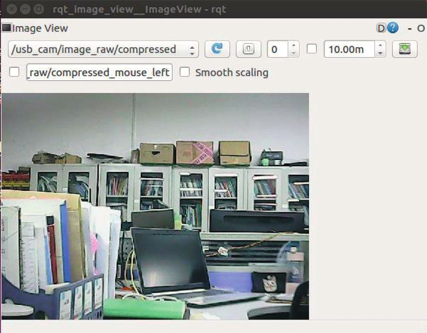
voice wake-up engine to achieve offline voice wake-up and 6.3. Camera Information Collection and Debugging. The
voice interaction. camera and the Raspberry Pi are directly connected through
the USB serial port. Then, the PC is connected to the
Raspberry Pi 3B remotely. The PC side runs the node
5.5.1. Baidu Speech Recognition API. We register an account
(usb_cam) that starts the camera in the Raspberry Pi 3B, and
on Baidu AI official website. Then, we create a speech
then the PC side runs the rqt_imsge_view tool to obtain the
recognition application and get the ID number and key as
image information of the camera as shown in Figure 19. By
follows:
adjusting the focus of the camera, clear image information is
(i) APP_ID � ‘16188196’ obtained.
(ii) API_KEY � ‘c8i1D8ncIKuUK8HOPYeESojR’
(iii) SECRET_KEY � ‘dhmLkQBjztATaDXrygYetKGQ 6.4. Human Infrared Detection Alarm Debugging. We issue
0k46EiPn’. commands to the service robot on the PC side. Let the10 Mobile Information Systems
W W W W
Input + + + + Output
b b b b
446 3
100 100 50 3
Figure 15: The final designed BP neural network model.
Table 1: Comparison of relative displacement estimation errors.
Time Attitude sensor Lidar Attitude sensor and lidar data fusion
1 0.536 0.403 0.100
2 0.478 0.512 0.050
3 0.494 0.511 0.060
4 0.501 0.496 0.030
5 0.564 0.500 0.041
6 0.478 0.533 0.091
... ... ... ...
45 0.580 0.494 0.196
46 0.700 0.601 0.136
47 0.674 0.632 0.133
48 0.601 0.678 0.145
49 0.654 0.631 0.101
50 0.625 0.589 0.091
1
0.9
0.8
0.7
0.6
Error (m)
0.5
0.4
0.3
0.2
0.1
0
0 4 8 12 16 20 24 28 32 36 40 44 48
Time
Attitude sensor
Lidar
Attitude sensor + lidar
Figure 16: Comparison of relative displacement estimation errors.
Figure 17: Effect picture before robot control.Mobile Information Systems 11
Figure 18: Effect picture after robot control.
Figure 19: Information collected by the camera.
infrared module of the human body start to detect if there is 7. Function and User Experience Comparison
a human being. The system uses Arduino mage2560 to
control the GSM module to call and send text messages to In order to reflect the advantages of the home service
users. This system can remind users in time by dialing. The robot designed in this article, we compared the robot
user can know the specific information of the alarm by function developed in this article with the robot func-
checking the short message. The test is shown in Figures 20 tion in the reference. We randomly selected 15 people,
and 21. and each person experienced the robots in the following12 Mobile Information Systems
Figure 20: Human infrared sensor detects someone.
Figure 21: View SMS messages.
table for two days and then scored the experience of robot designed in this article has more complete func-
each robot. The results of the survey are shown in Table 2. tions than other robots, and the user experience is the
It can be seen from the table that the home service best.Mobile Information Systems 13
Table 2: Survey results.
Literature Features User experience
Temperature and humidity measurement, camera, light control, flame/smoke alarm, human ∗∗∗
Reference [7]
body infrared sensor
∗∗
Reference [5] Human-computer interaction
∗∗∗∗
Reference [12] Voice communication, face recognition, human-computer interaction
∗
Reference [14] Wireless sensor and robot communication
∗∗
Reference [13] Speech recognition, human-computer interaction
∗
Reference [15] Wireless control
∗∗
Reference [16] Robot walking (balanced walking motion)
Robot walking, wireless communication, hazard alarm, autonomous navigation, indoor
The robot designed in this ∗∗∗∗∗
positioning, voice control, control of home appliances, human infrared detection warning,
article
camera information collection
8. Conclusion Acknowledgments
Currently, smart home service robots have fewer functions, The authors are highly thankful to the Research Project for
and it is difficult to meet people’s needs for a comfortable, Young and Middle-Aged Teachers in Guangxi Universities
convenient, safe, and fun home life. And they still generally (ID: 2019KY0621), to the Natural Science Foundation of
lack the ability to independently complete the task of Guangxi Province (No. 2018GXNSFAA281164), and to the
combining autonomous patrols and home services. In re- support by National Natural Science Foundation of China
sponse to this problem, this article has researched and de- (No. 62063006). This research was financially supported by
veloped a home robot system that has complete functions the project of outstanding thousand young teachers’ training
and can independently complete the task of combining in higher education institutions of Guangxi, Guangxi Col-
autonomous patrols and home services. The system is based leges and Universities Key Laboratory Breeding Base of
on ROS to design a smart home service robot system. It uses System Control and Information Processing.
the framework and principles of the ROS system to build a
distributed computing system through message publish- References
subscribe. The ZigBee networking structure between the
CC2530 chip, the coordinator, and the terminal nodes is [1] S. Gürel, H. Gultekin, and V. E. Akhlaghi, “Energy conscious
used to realize the ZigBee wireless networking. The voice scheduling of a material handling robot in a manufacturing
control service robot is realized by Baidu AI voice recog- cell,” Robotics and Computer-Integrated Manufacturing,
nition API. Using the combination of lidar and attitude vol. 58, pp. 97–108, 2019.
sensor, the service robot realizes the establishment of maps [2] G. Niu, B. Pan, Y. Fu et al., “Development of a new medical
robot system for minimally invasive surgery,” IEEE Access,
and autonomous navigation of the indoor environment.
vol. 8, pp. 144136–144155, 2020.
Compared with related home service robots, the home [3] J. W. Jia, N. Chung, and J. Hwang, “Assessing the hotel service
service robots researched and designed in this paper have robot interaction on tourists’ behaviour: the role of anthro-
relatively sound functions and at the same time complete the pomorphism,” Industrial Management & Data Systems,
task of combining independent inspections with home vol. 121, 2021.
service. Compared with other home service systems, the [4] Y. Sun, L. Guan, Z. Chang et al., “Design of a low-cost indoor
system designed in this paper has a better user experience, navigation system for food delivery robot based on multi-sensor
making the user’s life more comfortable, convenient, safe, information fusion,” Sensors, vol. 19, no. 22, 4980 pages, 2019.
and fun. [5] J. Saunders, D. S. Syrdal, K. L. Koay et al., ““Teach me–show
me”—end-user personalization of a smart home and com-
panion robot,” IEEE Transactions on Human-Machine Sys-
Data Availability tems, vol. 46, no. 1, pp. 27–40, 2015.
[6] World Health Organization, 10 Facts on Ageing and the Life
The data used to support the findings of this study are in- Course, World Health Organization, Geneva, Switzerland,
cluded within the article. 2014, http://www.who.int/features/factfiles/ageing/en/.
[7] R. Turjamaa, A. Pehkonen, and M. Kangasniemi, “How smart
homes are used to support older people: an integrative re-
Conflicts of Interest view,” International Journal of Older People Nursing, vol. 14,
The authors declare that they have no conflicts of interest to no. 4, Article ID e12260, 2019.
[8] M. R. Alam, M. B. I. Reaz, and M. A. M. Ali, “A review of
report regarding the present study.
smart homes—past, present, and future,” IEEE Transactions
on Systems, Man, and Cybernetics, Part C (Applications and
Authors’ Contributions Reviews), vol. 42, no. 6, pp. 1190–1203, 2012.
[9] K. Wada, T. Shibata, T. Asada et al., “Robot therapy for
Jiansheng Peng, Hemin Ye, Yong Qin, and Zhenwu Wan prevention of dementia at home,” Journal of Robotics and
contributed equally to this work. Mechatronics, vol. 19, no. 6, 691 pages, 2007.14 Mobile Information Systems
[10] D. Lee, T. Yamazaki, and S. Helal, “Robotic companions for
smart space interactions,” IEEE Pervasive Computing, vol. 8,
no. 2, pp. 78–84, 2009.
[11] D. Portugal, P. Alvito, E. Christodoulou et al., “A study on the
deployment of a service robot in an elderly care center,”
International Journal of Social Robotics, vol. 11, no. 2,
pp. 317–341, 2019.
[12] N. H. Abdallah, E. Affes, Y. Bouslimani, M. Ghribi,
A. Kaddouri, and M. Ghariani, “Smart assistant robot for
smart home management,” in Proceedings of the 020 1st In-
ternational Conference on Communications, Control Systems
and Signal Processing (CCSSP), pp. 317–321, El Oued, Algeria,
March 2020.
[13] J. Berrezueta-Guzman, I. Pau, M. L. Martı́n-Ruiz et al.,
“Smart-home environment to support homework activities
for children,” IEEE Access, vol. 8, pp. 160251–160267, 2020.
[14] W. Wang Huiyong, W. Huang Min, and H. Min, “Building a
smart home system with WSN and service robot,” in Pro-
ceedings of the 2013 Fifth International Conference on Mea-
suring Technology and Mechatronics Automation,
pp. 353–356, Hong Kong, China, January 2013.
[15] H. Hsu, K. Yu, W. Ouyang, and C. J. Xu, “Constructing a
smart home control system with the Internet of things,” in
Proceedings of the 2018 IEEE Asia-Pacific Conference on
Antennas and Propagation (APCAP), pp. 1-2, Auckland, New
Zealand, August 2018.
[16] W. Guan, S. Chen, S. Wen et al., “High-accuracy robot indoor
localization scheme based on robot operating system using
visible light positioning,” IEEE Photonics Journal, vol. 12,
no. 2, pp. 1–16, 2020.
[17] O. P. Bodunde, U. C. Adie, O. M. Ikumapayi et al., “Archi-
tectural design and performance evaluation of a ZigBee
technology based adaptive sprinkler irrigation robot,” Com-
puters and Electronics in Agriculture, vol. 160, pp. 168–178,
2019.
[18] I. González and A. J. Calderón, “Integration of open source
hardware Arduino platform in automation systems applied to
Smart Grids/Micro-Grids,” Sustainable Energy Technologies
and Assessments, vol. 36, Article ID 100557, 2019.
[19] S. Song, X. Xiong, X. Wu et al., “Modeling the SOFC by BP
neural network algorithm,” International Journal of Hydrogen
Energy, vol. 46, no. 38, pp. 20065–200077, 2021.You can also read