Designing and investigation of braided-cum-woven structure for wearable heating textile - IOPscience
←
→
Page content transcription
If your browser does not render page correctly, please read the page content below
Engineering Research Express

PAPER

Designing and investigation of braided-cum-woven structure for
wearable heating textile
To cite this article: Akanksha Pragya et al 2020 Eng. Res. Express 2 015003

View the article online for updates and enhancements.

                               This content was downloaded from IP address 176.9.8.24 on 01/03/2020 at 17:03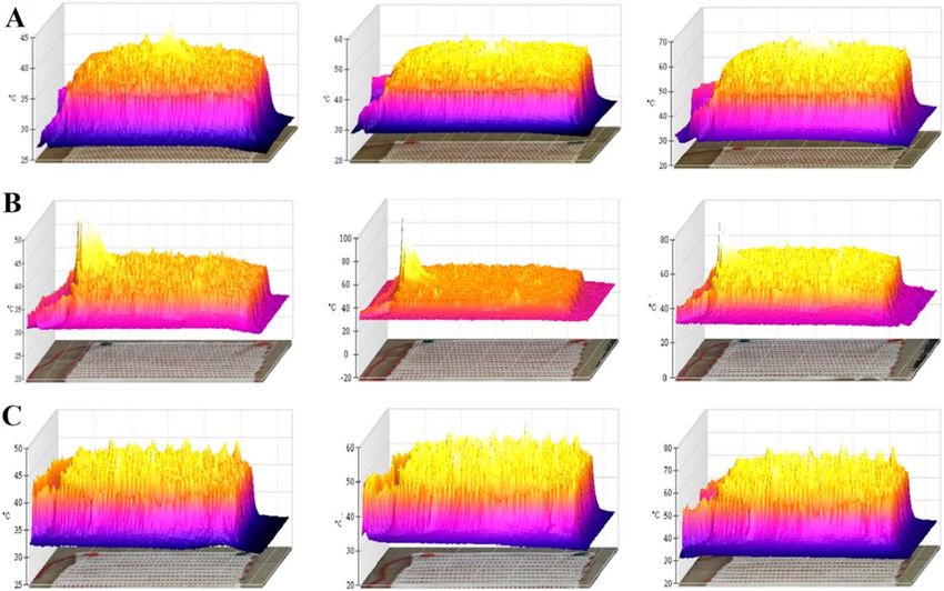
Eng. Res. Express 2 (2020) 015003                                                              https://doi.org/10.1088/2631-8695/ab63f3

                           PAPER

                           Designing and investigation of braided-cum-woven structure
RECEIVED
2 September 2019
                           for wearable heating textile
REVISED
18 December 2019
ACCEPTED FOR PUBLICATION
                           Akanksha Pragya          , Himanshu Singh, Bipin Kumar , Harsh Gupta and Promod Shankar
19 December 2019           Department of Textile Technology, Indian Institute of Technology Delhi, Hauz Khas, New Delhi-110016, India
PUBLISHED
                           E-mail: bipin@textile.iitd.ac.in
6 January 2020
                           Keywords: braiding, conductive yarn, thermal conductivity, e-textile, heating textile, heating garments, active heating garment

                           Abstract
                           The present research makes use of a braiding-cum-weaving technique for the fabrication and
                           investigation of electricity-induced heating fabrics. Braided conductive yarns (BCYs) were produced
                           using a Maypole braiding machine by introducing conductive copper filament as the core and
                           polyester multifilament yarn as the sheath. A different number of polyester yarns, 6-, 10- and 16-end,
                           were used to cover the copper core. Electrically heating fabrics (e-HFs) were fabricated by interweaving
                           the BCYs through pick insertion in a plain-woven construction at 4-, 8- and 12-pick spacing. Various
                           electro-mechanical tests were carried out on the BCYs and e-HFs. The mechanical performance of
                           16-end BCY was the most superior while 6-end BCY exhibited the poorest performance amongst
                           the three BCY-types. The temperature profiles obtained via thermal mapping elucidate the difference
                           in the heat-barrier effect of each of the BCYs. It also shows the presence of overlapping concentric
                           (cylindrical) isotherms running along the axes of the BCYs. These isotherms have shown to
                           significantly affect the temperature uniformity on the e-HF surface. Heating response under different
                           variables—pick-spacing, time, voltage and input power, were evaluated, and direct correlations were
                           found. A temperature of about 89.8 °C was attained at 5 V after 40 min of heating. For an input power
                           of 3, 5 and 7 W, a maximum temperature of 40.5, 48.8 and 55.3 °C was measured for different e-HFs.
                           Wash and sweat durability tests were also carried out to corroborate the utility of the e-HFs for day-to-
                           day usage. These tests proved to have a minimal detrimental effect on the heating performance of the
                           e-HFs establishing a good utilitarian quotient of such material for the purpose of wearable electronics
                           and essentially, as active heating garments.

                           1. Introduction

                           Recent developments in the field of wearable electronics have demarcated new areas of application like sensors,
                           healthcare, defense, and ergonomic monitoring. Simultaneously, a lot of focus has been shifted towards heating
                           fabrics and garments like electrothermal jackets, heated gloves, and belts with active thermal properties [1, 2]. A
                           number of studies to date have discussed the performance benchmark of functional textiles for the purpose of
                           product development for a wide range of applications. Necessary safety limits and commercial standards were
                           also discussed explicitly [3–8]. Additionally, to assert the credibility of the relevant properties, a few researchers
                           have attempted to simulate real-life situations through live tests on human bodies and mannequins. The
                           advantages of electronic textiles as well as the underlying loopholes have also been studied in thorough detail
                           [8, 9]. Depending on their mode of heating, Wang et al [9–14] have classified heating fabric majorly into four
                           different classes—electrically heated fabrics, heating fabrics based on phase change materials, chemically heated
                           fabrics and fabrics heated through the aid of fluid or airflow. The present paper is a focused investigation into the
                           fabrication and performance of electrically heating fabrics.
                                A number of methods have been employed to impart electrical properties to the woven, knitted and non-
                           woven textile fabrics. These include methods of coating via electrospinning [15, 16], solution impregnation,
                           in situ polymerization [17, 18], and nanocoating [19] of conductive materials like graphene, single/multi-walled

                           © 2020 IOP Publishing Ltd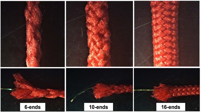
Eng. Res. Express 2 (2020) 015003 A Pragya et al
Table 1. Relevant properties of various conductive metal filaments.
Material Resistivity, ρ (Ω.m) Conductivity, σ (S.m−1) Temperature coefficient (K−1) Young modulus (GPa) References
Copper 1.68×10⁻⁸ 5.96×10⁷ 0.00404 128 [41]
Silver 1.59×10⁻⁸ 6.31×10⁷ 0.00382 69 [41]
Aluminium 2.65×10⁻⁸ 3.77×10⁷ 0.00391 70 [42]
Nickel 6.99×10⁻⁸ 1.43×10⁷ 0.00601 190 [3]
carbon nanotubes, silver nanoparticles, etc [20–25] on fabric substrate. Other approaches include the
introduction of metallic or metal-coated fibers and yarns [20] through weaving, braiding, knitting or
embroidery [26–28]. For instance, wearable electronic garments were fabricated by weft insertion of cotton
coated nichrome and copper yarn using handloom and power loom [28]. For the production of conductive
filaments, nickel, iron, stainless steel, chromium, brass, bronze, silver, gold, aluminum, etc is widely used.
However, stainless steel is the most commonly used material of all due to its non-toxicity, rust resistance,
recyclability, and long life. On the other hand, weaving and knitting have been most commonly employed to
fabricate conductive textile substrates [10, 29–32]. Incorporation of bare metallic wires into wearable textile
electronics is mostly avoided due to the possibilities of rashes, cuts or burns on the skin. Therefore, an insulating
sheath is put through wrapping, coating, braiding, etc to ensure a more comfortable user experience. The high
surface smoothness of bare filaments leads to poor gripping within the fabric structure. The absence of inter-
yarn friction results in unstable conformation, negligible fabric assistance, and improper fabric cover. Moreover,
an insulating layer can slow down the rate of surface modification and oxidation of the inner yarn under
atmospheric conditions over a prolonged time period.
Hybrid yarn with a conductive core has been widely produced using the ring spinning system. A common
problem with ring spinning is the slippage of the sheath fibers that leave the core filament bare and exposed to
the surface (‘strip back’ or barber-pole effect) [33]. Methods like air-texturing are also present but the stringent
nozzle air pressure damages the core [34]. Coating yarn and fabric with conducting polymers via spraying,
vaporization, solution coating, and polymerization calls for complex and time taking processing. It also leads to
harmful by-products and involves huge costs for liquid-waste treatment. Literature has shown instances where
metallic yarn (nichrome, copper, aluminum, stainless steel, etc) were wrapped around textile yarn (pristine
cotton, nylon, etc). But the subsequent hybrid yarns produced are unnecessarily brittle and incompatible with
the existing textile processes and machinery [33]. Thus, after due consideration of all these issues, the fabrication
of conductive yarn through the braiding technique was chosen. By the common understanding of the braided
structure, it is evident to expect a fewer chance of core filament undergoing knotting, breaking, and sharp point-
bending. The tubular braided structure maintains the mechanical strength of core yarn by decreasing the stress
concentration generated at the point of bending [35]. Also, previous studies have established that the braiding
technique leads to higher mechanical properties of the fabricated yarns [27, 36–39].
As discussed previously, a number of metallic alternatives are available to impart electrical conductivity to an
electrical fabric. Table 1 shows the values of some of the commonly used materials measured at 20 °C. The
amount of heat produced in an electrically heating fabric is governed by Ohm’s law of heating. The power
generated is directly proportional to the value of resistance. This power is dissipated in the resistor and
transferred to its surroundings through Joule’s heating [40]. Thus, to achieve the best heating performance, a
copper filament was chosen as the core of the BCYs.
The present study is an attempt to design electrically heating fabric by incorporating the cotton substrate
with BCYs via weft insertion during weaving on a Heddle loom. An assessment of the BCY structure, its
mechanical properties, the heating behavior of the e-HFs, along with the scope of its application has been
included—in order to visualize the portability and utility of the e-textiles as active heating garment components.
Past few reports on braids have recommended braided structures to be highly efficient in the protection of the
conductive core wires from abrasion and humidity [43]. Thus, washing and sweat durability analysis were
included in the assessment of the electro-thermal and the electro-structural performance of the electrically
heating fabric system.
2. Materials and methods
2.1. Preparation of braided conductive yarns
To develop the braided conductive yarns (BCYs), copper wire of diameter 0.784 mm and linear density 116 tex
was used as the temperature-sensitive conductive core. Copper wire was purchased from Protocentral A
Division of Circuitects, Electronic Solutions Pvt. Ltd, Bangalore, India. Braiding was carried out on a maypole
2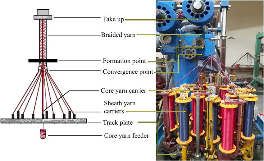
Eng. Res. Express 2 (2020) 015003 A Pragya et al
Figure 1. Braided conductive yarns with single copper core covered with 6-, 10-, and 16-end polyester sheath. The braiding angles are
76°, 96°, and 120° respectively.
Figure 2. Illustration of schematic and actual image of maypole braider used for the production of braided conductive yarns with
copper core.
braiding machine from Yiwu Wenli Weaving & Zipper Machinery Co. Ltd to make 6, 10 and 16-end BCYs,
shown in figure 1. Polyester multifilament (Petrorays Products Co., Mumbai, India) of linear density of 154 tex
were braided on a 16-carrier maypole circular braiding machine for the production of regular 1×1 sheath on a
copper core being held in the middle by the core-yarn carrier. Figure 2 shows the maypole braider that consists of
two sets of yarn carriers rotating on a circular track in which half of the carriers rotate in a clockwise direction
and the remaining half of the set rotates in a counter-clockwise direction. In this study, the regular braided
conductive yarn consisting of 6, 10 and 16 filaments (or ends) were produced on the circular braiding machine at
a take-up speed of 0.60 cm s−1 and rotational horn-gear speed of 16.50 rad s−1.
3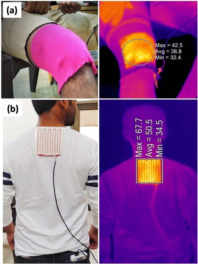
Eng. Res. Express 2 (2020) 015003 A Pragya et al
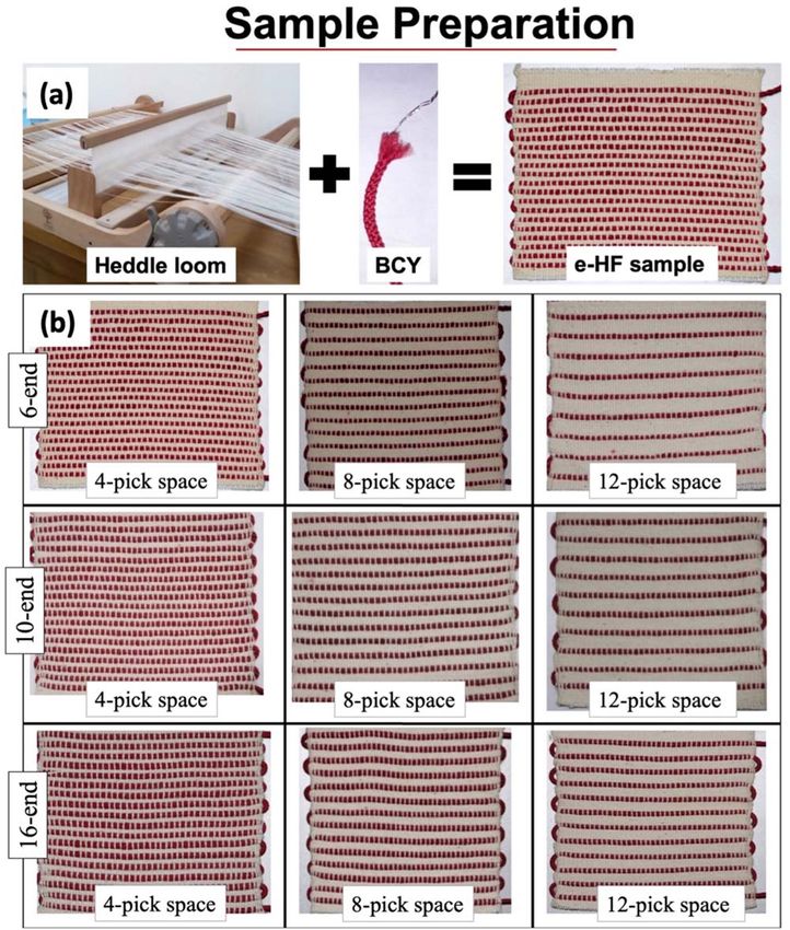
Figure 3. (a) Fabrication of electric heating fabrics (e-HFs) using polyester-copper braided yarn via pick insertion during weaving on a
heddle loom. (b) Final e-HFs samples fabricated by the integration of braided copper yarn at 4-, 8-pick, and 12-pick spaces.
Table 2. Nomenclature of the e-HF samples.
BCY-type 6-end 6-end 6-end 10-end 10-end 10-end 16-end 16-end 16-end
BCY-space 4-pick 8-pick 12-pick 4-pick 8-pick 12-pick 4-pick 8-pick 12-pick
Sample Code HF6,4 HF6,8 HF6,12 HF10,4 HF10,8 HF10,12 HF16,4 HF16,8 HF16,12
2.2. Preparation of electric heating fabric
The electric heating fabric (e-HF) was developed by the integration of the BCYs into the cotton fabric during
weft (or pick) insertion. As illustrated in figure 3(a), a two-heald frame, 32-inch wide Ashford Weaving Rigid
Heddle Loom was employed for weaving three variations of e-HFs by inserting the BCYs at 4-, 8- and 12-pick
spacing. Cotton yarn, linear density of 134 tex, was acquired from Petrorays Products Co., Mumbai, India and
was used to make the fabric substrate for e-HF, with an EPI and PPI values of 25 each as shown in figure 3(b). The
nomenclatures of the prepared samples are mentioned in table 2, for perusal for further discussion.
2.3. Measurement of basic properties of BCYs
For measuring the diameter, 1 m sample of the polyester sheath yarn, the copper core and the BCYs were
observed under a microscope. Approximately twenty-five readings of each sample were taken and averaged out
before reporting. The asymmetric selection of horn gear during braiding of the 6- and 10-end sheaths might
4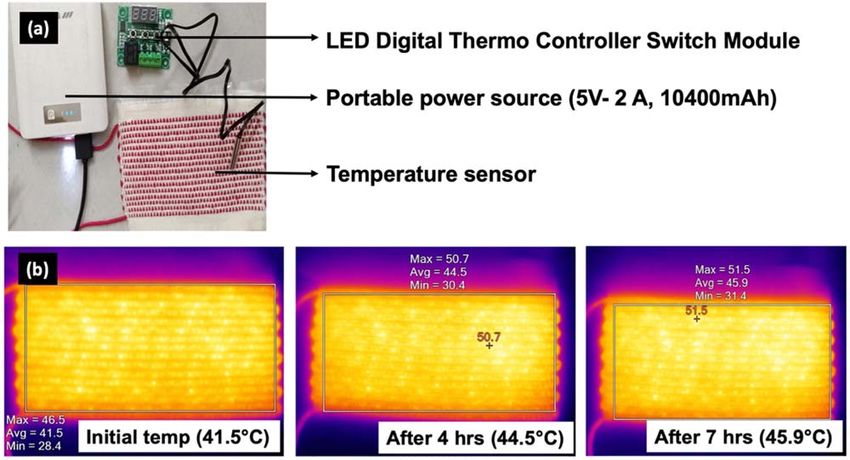
Eng. Res. Express 2 (2020) 015003 A Pragya et al
Figure 4. Experimental setup for the heat mapping and image of heat trace result of BCY embedded e-HF.
Table 3. Specifications and basic properties of BCYs.
Sample Braid angle (°) Diameter (mm) Linear density (ktex) Resistance (Ω/m)
6-end 76.00±0.05 2.00±0.04 1.051±0.10 2.428±0.48
10-end 95.00±0.21 2.31±0.08 1.550±0.07 2.119±0.02
16-end 120.00±0.11 2.50±0.07 1.881±0.16 1.519±0.91
have induced a slight non-uniformity in the braided yarns. Thus, acknowledgment of standard deviations was
important to gauge the degree of unevenness in the BCY samples. Braiding angles were measured by capturing
the images of biaxial braids and then analyzing with ImageJ® software [44]. An average of twenty readings were
recorded for determining the braid angles. The electric resistances of BCYs were measured by a Fluke 8846A
6-1/2 digit precision multimeter. All tests were performed in a laboratory at standard ambient temperature,
25 °C and pressure, 1 atm (SATP). The specifications and basic properties of the prepared samples are tabulated
in table 3.
2.4. Mechanical testing of BCYs and e-HFs
The tensile test was carried out for the BCYs on a universal tensile tester machine INSTRON 5566 with 500 N
load cell at a cross-head velocity of 100 mm min−1 at a gauge length of 250 mm by ASTM D6775−13.
Maintaining similar cross-head velocity and gauge length, the tensile testing of the polyester yarn and copper
filament was done according to ASTM 2256.
Fabric bending was done using Shirley Stiffness Tester as per ASTM D1388-18. A horizontal strip
(200 mm×25 mm) of fabric is slide on a horizontal plate. The length of the overhang is measured when the tip
of the specimen is depressed under its own mass. This measured length is used to calculate the flexural rigidity of
the fabric along weft direction according to the following formula;
⎡ ⎛q ⎞ ⎤
⎢ cos ⎝⎜ ⎠⎟ ⎥
2 ⎥
G = M .L3 ⎢ (1)
⎢ 8 tan q ⎥
⎢⎣ ⎥⎦
Where G is the flexural rigidity, M is the mass per unit area (g/m2), and θ is the angle fabric bends at (θ=7.1
rad), L is the bending length at θ=7.1 rad (mm).
2.5. Infrared heat mapping of BCYs and e-HFs
The conductive material generates heat when current is passed through it. In order to understand the
subsequent heat generation and distribution over the surface both in the transverse and longitudinal direction,
heat mapping of the BCYs, as well as the e-HFs was carried out through Fluke TIS20 9HZ Thermal (120×90
resolution) Infrared Camera at SATP. The current was passed through the heating-element an external variable
DC voltage source (60V/5A). The emissivity of the system was about 95%, and the distance of the lens from the
test sample was 35 cm, as shown in figure 4. The electric heat generated over a given period of time was calculated
via Ohm’s law of heating;
5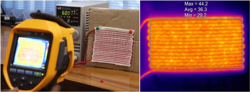
Eng. Res. Express 2 (2020) 015003                                                                            A Pragya et al

   Figure 5. Load-elongation curves for copper, polyester and 6-, 10- and 16-end braided conductive yarns.

                                                            H = I 2. R. t                                              (2)

Where H is the heat generated (joules, J), I is the current passing through the heating element (amperes, A) and t
is the time-period for which the heat generation is calculated (seconds, s).
     Maximum equilibrium temperature (MET) of e-HF surface with time and loaded voltage was measured
[45]. The effect of pick spacing over the surface of e-HFs was also studied. Heating performance and saturation
time were also studied as a function of input power. For supplying net power (P) of 3, 5, and 7 W, the calculation
of input voltage (V) for the e-HFs was done by

                                                                    V2
                                                             P=        .                                               (3)
                                                                    R

    The heating stage, equilibrium temperature stage and the cooling stage were respectively mapped via
infrared temperature images and subsequently, the three-dimensional temperature images of MET over the
surface of the e-HF were obtained.

2.6. Wash and sweat durability
For the assessment of the durability of structure and heating performance, all the three types of 4-pick spaced
e-HFs (HF10,4, HF10,8, and HF10,12) were subjected to machine laundry test. Samples were washed for 30 min
using a washing machine (manufacturer: Whirlpool) in the warm wash setting of 30 °C at 800 RPM to simulate
real domestic washing [46]. After each wash, the samples were air-dried at SATP for 12 h before they were
subjected to further tests and the next round of washing. Five wash cycles were repeated for each sample, and
readings were averaged out before reporting.
    Human body, when exposed to heat, is prone to sweat or perspiration. Testing under sweating directly on
the human body is difficult to achieve due to high variability amongst individuals. To examine heating behavior
under sweating condition, a simulated environment was staged. A handheld steam gun (Model: Shoreless RZ-
608) was used to spray steam directly on the heating area of the HF10,4, HF10,8, and HF10,12 samples for 10 s.
Thermal mapping for each sample was taken directly after the test without drying them. The saturation
temperature values were recorded at three instances and used for comparison.

3. Result and discussion

3.1. Tensile performance of BCYs
The force-elongation curve of the braided yarn in figure 5 shows a linear nature. This is atypical to the
conventional non-linear tensile behavior of braided yarn. In the usual case of braids, initially, a linear behavior is
observed due to the frictional resistance offered by the constituent filament. Thereafter, a plateau region is
observed, indicating crimp interchange. Finally, a linear region reappears, indicating the jamming of the braided
structure [47]. Therefore, an all-linear nature of the curve in figure 5 indicates that the jamming has not been
realized. A similar force-elongation curve has been reported in previous literature [48].

                                                        6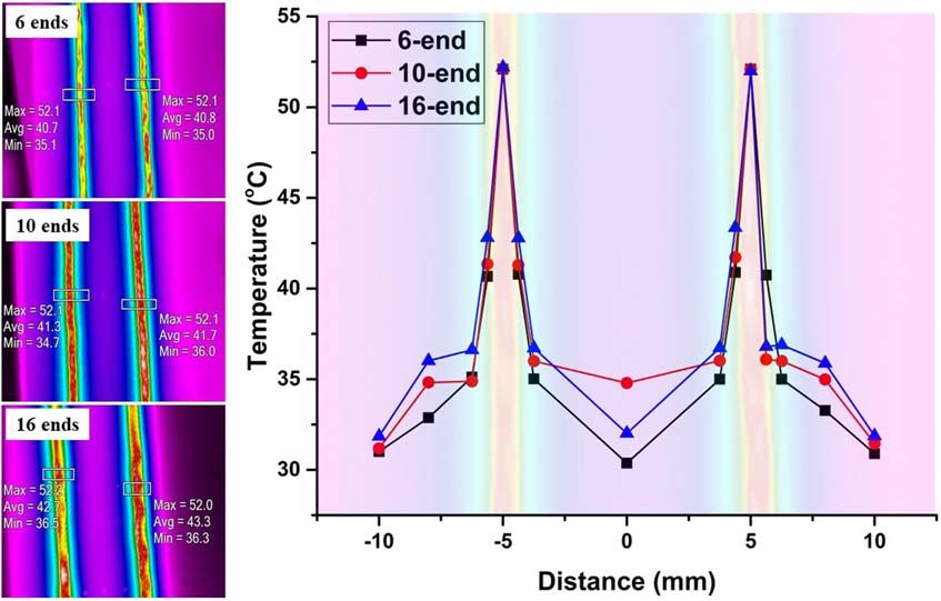
Eng. Res. Express 2 (2020) 015003 A Pragya et al
Figure 6. (a) Heat maps of 6-, 10- and 16-end BCYs when a voltage of 3 V is applied across each of them, (b) Temperature variation
around BCYs immediate environment.
Table 4. Results of tensile test of the BCYs.
Braid
angle Breaking Breaking
Sample (°) strength (N) elongation (mm)
Copper — 3.75±0.10 6.48±0.15
Polyester — 26.54±2.32 33.15±1.28
6-end BCY 76 205.97±10.20 54.86±0.27
10-end BCY 95 295.33±9.77 65.90±1.49
16-end BCY 120 348.73±4.10 69.96±0.68
The tensile test results for polyester, copper and 6-, 10- and 16-end BCYs are summarized in table 4. It is
observed that as the end-values increase, the tensile properties increase proportionally. The measured values of
braid angles are 76°, 96°, and 120°. The breaking strength and breaking elongation from table 4 clearly state that
the braiding angle has a direct correlation with the tensile properties of the BCYs. The elongation at break
increases with increasing the braiding angle. Because of the braided structure, the yarns are in a crimped state.
Hence, when force was applied during the tensile test, the yarns take time to axially arrange itself [49], and a high
braiding angle adds flexibility to the structure. Tensile properties are also dependent on the number of yarn-ends
in each BCY. A higher number of yarn-ends (at higher braid angle) led to a more compact structure. This
hampers the sliding of the braid yarns and the rearrangement of the braid geometry under external load.
Previous studies have reported that the rubbing of yarns against each other imparts extra strength to the braid
structure. Thus, the tensile strength of the BCYs increases as the number of yarn-ends increases [48].
It must be noted that lower breaking strength of copper core wire (3.75±0.10 N), serving as common core
material, is still the limiting factor in determining the tensile property of the BCYs. Through visual observation,
the internal BCY-diameters (Di) and copper’s external diameter (de) do not appear the same. This produces a gap
(Di − de) inside the BCYs, which is reflected in the heat maps in figure 6(a). The space inside the braided
structure enables the accommodation of a greater length of copper wire (l) within a given BCY length (L); by
acquiring a twisted configuration. The difference (l - L) increases as the number of yarn-ends increases. The
twisted layout straightens whenever the BCY is stretched during a tensile test. This is how their electrical
properties are kept intact even at a strain value beyond the breaking elongation of copper wire.
3.2. Infrared heat mapping of BCYs
3.2.1. Effect of distance on heating profile
A line source of heat based on Ohm’s law of heating can be created experimentally by a thin wire. This electricity-
induced heat gets transferred to the surrounding fluid (here, air) by the mechanism of steady free convection.
Agitated molecules near the heated core set in motion a process of molecular diffusion and the isotherms, in the
7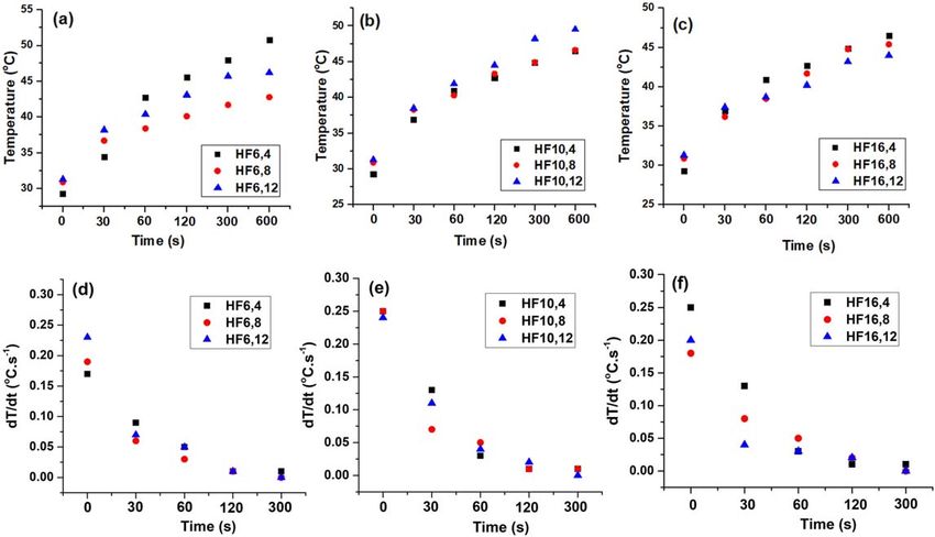
Eng. Res. Express 2 (2020) 015003 A Pragya et al
Figure 7. Time versus temperature trend for maximum equilibrium temperature obtained for 6-, 10- and 16-end BCYs.
Figure 8. Effect of voltage applied to the performance of a 6 ends conductive braided yarn.
form of concentric cylinders, are formed [50–54]. Temperature mapped at 3 V around the BCYs are shown in
figures 6(a) and (b). The highest temperature drop was observed in 16-end BCY and lowest in 6-end BCY. This
may be due to the highly compact structure of PP sheath which results in a stronger barrier effect against the
outward heat propagation. The effect diminishes for a relatively low packed structure of 10- and 6-end BCYs.
Only two readings out of the total four taken are reported here for reference.
3.2.2. Effect of time on heating profile
As time proceeds from 0 to 15 min, average temperature (at 3 V) increases in proportional to time, according to
equation (2). Starting from the same initial temperature of 25±2 °C, it increases by 102.9, 106 and 120% for 6-,
10- and 16-end BCYs respectively, as shown in figure 7. The maximum temperature is obtained for 16-end BCY
and minimum for 6-end BCY. This is in coherence with the barrier effect which is most significantly present in
the former than the latter.
3.2.3. Effect of voltage on heating profile
Applied voltage has a direct effect on the surface temperature of the e-HFs. To quantify this, a 6-end BCY (initial
temperature 32 °C) was subjected to a step-wise increase in voltage from 2 V up to 5 V. Figure 8 shows the values
of equilibrium surface temperature obtained at different voltage. By an alternate version of Ohm’s law of heating
(equation (2)), heat produced in a current-carrying medium is directly proportional to the second power of
8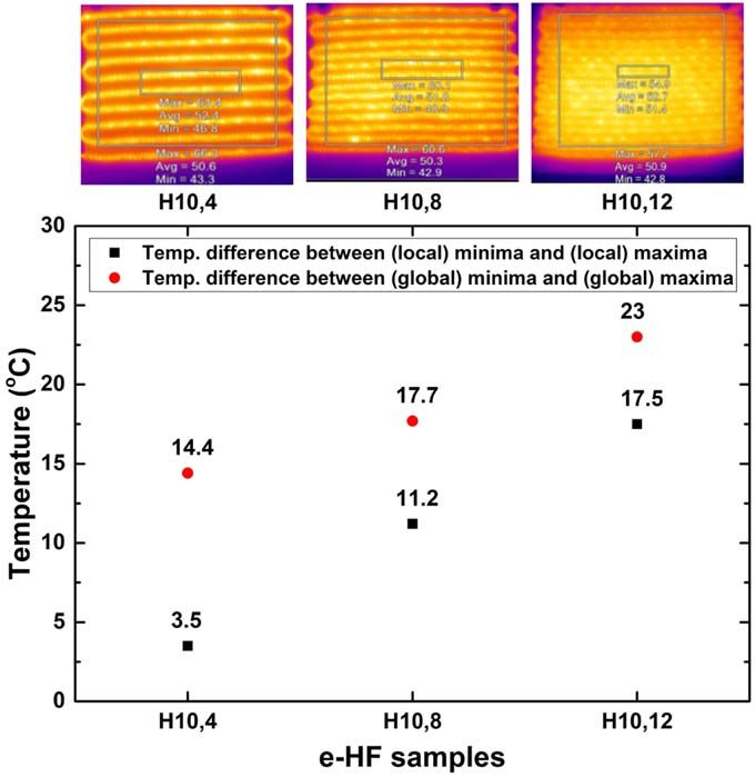
Eng. Res. Express 2 (2020) 015003                                                                                        A Pragya et al

   Figure 9. (a)–(c) heating of e-HFs with time (d-f) Rate of increase of temperature in each fabric sample with time.

voltage applied to it and is inversely proportional to its resistance [45]. Here, the effect of resistance is nullified by
using a single type of (6-end) BCY for the measurement of the heat produced.

3.3. Flexural rigidity of e-HFs
Measured flexural rigidity values of H10,4, H10,8 and H10,12 were 397.91, 322.86 and 296.94 μJ m−1. It is observed
that high pick spacing leads to a stiffer structure due to a corresponding increase in the BCY compactness. This
proves beneficial to sustain high mechanical impacts like those during bending or washing. A good flexural
rigidity will support e-HFs to maintain its electro-structural robustness by preventing breakage of copper core,
damage to the braided structure, etc.

3.4. Infrared heat mapping of e-HFs
Heat mapping of e-HFs is important to understand the intensity of the heat produced, its distribution and
homogeneity over the heating fabric surface. Results of e-HFs fabricated using 10-end BCY only are shown here
for the purpose of clarity.

3.4.1. Time-variant heating profile
As time progresses, there is an increase in the MET of each of the e-HFs. The fabric samples were tested at 5.3 V
(6 W) by passing a current of 1.12 A. It must be noted that the saturated temperature in figures 9(a)–(c) is
considerably lower than those for individual BCYs in figures 6(a) and (b). This is because of the temperature
difference in global minima and global maxima over the surface of the e-HF. Thus, the average surface
temperature is lowered due to the presence of global minima. As discussed in section 3.2.3, the temperature
increase can be explained on the basis of Ohm’s law of heating. In the case of 6-end BCY (figure 9(a)), the
maximum increase in temperature (73.37%) is observed for HF6,4 fabric. In figure 9(b), the highest increase in
temperature is found in HF10,12 (58.87%) while in figure 9(c), it is observed in HG16,4 (54.95%).
    As the diameters of BCYs increase, the rate of increase in temperature diminishes. It may be explained via the
barrier effect property of the BCYs. Highly compact 16-end BCY causes more heat to restrict around the
immediate premise of the copper core. However, the close spacing of 4-pick (even for low compact 6-end BCYs)
leads to a higher (average) surface temperature due to constructive overlaps of local concentric isotherms. These
overlap in between two adjacent BCYs form regions of elevated temperature. As a result, a comparatively higher
temperature is seen in a 4-pick spaced e-HF in figures 9(a)–(c). Thus, the average temperature of e-HFs is
dependent equally on the BCY-thickness and pick-spacing. The time derivatives of temperature in figures 9(d)–(f)
show a gradual decrease with time. To further validate the above results and study heating behavior, the effect of a
step-wise voltage fluctuation was done on HF6,4 over a range of time (figure 10).

                                                          9
Eng. Res. Express 2 (2020) 015003 A Pragya et al
Figure 10. Temperature profile of HF6,4 under different values of voltage, measured over progressing time range of 0-10 min.
Figure 11. Time versus temperature trend for maximum equilibrium temperature obtained at the surface of HF10,4 HF10,8 and
HF10,12.
3.4.2. Effect of Pick Spacing on Heating Profile
Figure 11 shows the heating profile of HF10,4 HF10,8 and HF10,12. The difference in the global temperature
maxima and minima of 14.4 °C was measured in HF10,4. The difference increased to 17.7 °C and 23.0 °C for
HF10,8 and HF10,12 respectively. This re-validates the fact that a lower pick-spacing corresponds to a more
homogenous heat production on the e-HF surface due to isotherm overlapping.
3.4.3. Effect of Input Power on Maximum Equilibrium Temperature (MET)
3-D mapping of e-HFs is shown in figure 12. It clearly shows that e-HFs at higher input power attain higher
surface saturation temperature. The saturation temperatures at 3, 5 and 7 watts of input power are tabulated in
table 5. As the voltage increases, the temperature of the e-HF increases in accordance with the direct correlation
of temperature with power [45].
3.5. Wash and sweat durability
One of the major setbacks of e-textiles is its durability against moist conditions like laundering and perspiration
[55–57]. To evaluate the mechanical and electrical strength of heating fabrics, heat mapping was done under
washed and sweat-simulated conditions. The resultant heat maps and average temperatures obtained are shown
10Eng. Res. Express 2 (2020) 015003 A Pragya et al
Figure 12. Three-dimensional temperature mapping of HF6,4, HF6,8 and HF6,12 at input powers of (from left to right) 3, 5 and 7 watts
respectively.
Figure 13. Saturation equilibrium temperature measured on the surface of the HF10,8 fabric after (a) wash durability test and (b) sweat
simulated test.
Table 5. Measurement of e-HFs saturation surface at 3, 5, and 7
watts input power.
Sample Power –3 W Power –5 W Power –7 W
HF6,4 38 °C 47 °C 55.3 °C
HF6,8 37.6 °C 43.9 °C 50.9 °C
HF6,12 40.5 °C 46.6 °C 53.5 °C
HF10,4 38.7 °C 47.4 °C 54.9 °C
HF10,8 39.2 °C 47 °C 53.8 °C
HF10,12 38.7 °C 45.1 °C 51.6 °C
HF16,4 39.9 °C 48.8 °C 55.3 °C
HF16,8 37.2 °C 44.4 °C 55.1 °C
HF16,12 38.6 °C 44.6 °C 52.1 °C
in figures 13(a) and (b). For the sake of clarity, results for only HF10,8 tested at 3, 5 and 7 W are included. The
retention of heating performance is higher in case of perspiration than washing. It may be explained on the basis
of the interim gap (Di − de), within the BCYs. Because perspiration is a dynamically slower and less harsh than
11Eng. Res. Express 2 (2020) 015003 A Pragya et al
Figure 14. (a) Portable power source connection (b) Continuous heating of the e-HF up to full battery use.
Figure 15. In lab medical product developed using e-HF for localized heating of affected area of (a) knee and (b) neck for muscle
relaxation and pain relief.
washing, the physical impact and effect of water (or moisture) is less damaging than washing. Moreover, the
simulated sweat-fluid is withheld on the surface of the sheath polyester by absorption. In this light, the gap
(Di − de) is beneficial because it acts as a barrier by preventing the conducting core from coming in direct contact
with the sweat. Despite this, the lowering in saturation equilibrium temperature for perspiration-fastness is
more than expected. This can be because for the sweat-simulated test, heat mapping was done while the e-HFs
were still wet, thereby, decreasing the average surface temperature.
12Eng. Res. Express 2 (2020) 015003 A Pragya et al
4. Application potential
To understand the efficiency of the presented e-HFs, its heating performance was studied by incorporating it in an
electric circuit and connecting to a portable power source, as shown in figure 14(a). The aim was to reduce the battery
size and connect the fabricated e-HF system to a thermos controller switch module to gauge its heating performance
as a portable heat source. Upon calculation for a battery source of 10400 mAh capacity, it was concluded that the
e-HF can remain functional for about 8.9 h in a temperature range of 41 °C–46 °C, shown in figure 14(b).
The potential area of application for the given e-HFs is medical healthcare, especially for physiotherapeutic
relief from muscular pain in the knee, neck, spine, etc [58–63]. Figures 15(a) and (b) shows one such application
where e-HFs are used to make thermal heating pads for localized heating of pain-affected area in the knee and neck
region. A sufficiently high temperature of 40 °C–50 °C was be obtained by supplying a rather small amount of
power input. The cooling down process also occurred over a prolonged period of time. This makes the e-HFs
highly favorable as heating garments or as medical heat massage products. These e-HFs are equally suitable for
application in motorbike gloves, and sports garments in low-temperature climate. These electrically heating fabrics
hold an equal potential to substitute leisure garments or woolen wear where the temperature regulation is easier.
5. Conclusion
The present study discusses a facile method for the fabrication of woven-cum-braided electrically heating fabrics
(e-HFs). Braided copper yarns (BCYs) were prepared by using 6-, 10- and 16-end polyester yarn as a sheath around
the copper core. The BCYs were then integrated into cotton fabric substrate at 4-, 8- and 12-pick spacing through pick
insertion during weaving on a Heddle Loom. The results from the electro-thermal experiments showed a significant
correlation between the numbers of yarn-end in the braid and the temperature-barrier effect of the BCYs. The dense
sheath structure of 16-end BCY enabled a higher heat-trapping within its immediate surroundings as compared to
6- and 10-end BCYs. Thus, a temperature drop of 17.1 °C, 15.7 °C and 14 °C was observed for 6-, 10- and 12-end
BCYs respectively. The temperature variation and maximum equilibrium temperature (MET) on the surface of
the e-HFs were mapped as well. Also, it was established that pick-spacing influenced fabric heating performance.
Closely spaced BCYs cause an increase in the overall surface temperature of the e-HFs due to overlapping cylindrical
isotherms. The effect of time, voltage and input power was also studied. For instance, it was shown that temperature
as high as 97 °C was achieved by applying 7 V for 40 min The e-HFs impart heat to its surroundings through the
steady convective mode of heat transfer. It holds strong potential to cater to wide application prospects as an active
heating garment. Contrary to conventional belief, the small diameters of the prepared BCYs and the method of its
integration with fabric substrate resulted in a higher sense of comfort when these e-HFs were used as active heating
garments in the laboratory-developed pain relief bandages. Yet, it is possible to create an even more stretchable and
comfortable fabric structure though other interlacement techniques like warp knitting. Such a structure will be purely
based on the BCYs without an intervening fabric substrate to hamper the conductive yarns from attaining their
highest potential temperature. Such a fabrication technique seems to be a perspective field for a different field of
study. However, the straight-forward fabrication method of weaving, the subsequent heating performance and
portability of e-HF systems discussed in the present paper satisfactorily endorse the scalability of the manufacturing
process of these heating fabrics and their utility as active heating garments in a wide range of human-centric heating
application.
Acknowledgments
The author would like to thank funding support from the Department of Science and Technology, India (Project
Codes: RP03454G, MI01695G).
ORCID iDs
Akanksha Pragya https://orcid.org/0000-0002-6013-5025
Bipin Kumar https://orcid.org/0000-0002-9754-8210
References
[1] Catrysse M, Puers R, Hertleer C, Langenhove L V, Egmond H V and Matthys D 2004 Towards the integration of textile sensors in a
wireless monitoring suit Sens. Actuators A Phys. 114 302–11
[2] Park S and Jayaraman S 2003 Enhancing the quality of life through wearable technology IEEE Eng. Med. Biol. Mag. 22 41–8
13Eng. Res. Express 2 (2020) 015003 A Pragya et al
[3] Hao L, Yi Z, Li C, Li X, Yuxiu W and Yan G 2012 Development and characterization of flexible heating fabric based on conductive
filaments Measurement 45 1855–65
[4] Wagner S, Bonderover E, Jordan W B and Sturm J C 2002 Electrotextiles: concept and challenges Int. J. High Speed Elect. Syst. 12 391–9
[5] Baurley S 2004 Interactive and experiential design in smart textile products and applications Pers. Ubiquitous Comp. 8 274–81
[6] Cottet D, Grzyb J, Kirstein T and Troster G 2003 Electrical characterization of textile transmission lines IEEE Trans. Adv. Pack. 26
182–90
[7] Haisman M F 2007 Physiological aspects of electrically heated garments Ergonomics 31 1049–63
[8] Wang F, Gao C, Kuklane K and Holmér I 2010 A review of technology of personal heating garments Int. J. Occup. Saf. Ergon. 16
387–404
[9] Ozan K, Ender B and Ozge S 2009 Implementation of steel-based fabric panels in a heated garment design Text. Res. J. 79 1427–37
[10] Hamdani S T A, Fernando A and Maqsood M 2016 Thermo-mechanical behavior of stainless steel knitted structures Heat Mass
Transfer 52 1861–70
[11] Wang F, Gao C, Kuklane K and Holmér I 2010 A review of technology of personal heating garments Int. J. OccupSaf. Ergon. 16 387–404
[12] Bai Y, Li H, Gan S, Li Y, Liu H and Chen L 2018 Flexible heating fabrics with temperature perception based on fine copper wire and
fusible interlining fabrics Measurement 122 192–200
[13] Akbar A R, Kamruzzaman M, Xu W, Gull S, Ahmed W and Khalid J 2016 Development of weft knitted heating pads on V-bed hand flat
knitting machine by using conductive yarns American Journal of Polymer Science & Engineering 4 133–41
[14] De Mey G, Özçelik M, Schwarz A, Kazani I, Hertleer C, Van Langenhove L and Gürsoy N Ç 2014 Designing of conductive yarn knitted
thermal comfortable shirt using battery operated heating system Journal of Textile & Apparel/TekstilveKonfeksiyon 24 26–29
[15] Liu Z H, Pan C T, Lin L W, Huang J C and Ou Z Y 2013 Direct-write PVDF nonwoven fiber fabric energy harvesters via the hollow
cylindrical near-field electrospinning process Smart Mater. Struct. 23 025003
[16] Inagaki M, Yang Y and Kang F 2012 Carbon nanofibers prepared via electrospinning Adv. Mater. (https://doi.org/10.1002/
adma.201104940)
[17] Bhat N V, Seshadri D T and Nate M M 2006 Development of conductive cotton fabrics for heating devices J. Appl. Polym. Sci. (https://
doi.org/10.1002/app.24708)
[18] Lee J Y, Park D W and Lim J O 2013 Macromol. Res. 11 481–7
[19] Xie L, Shan B, Xu H, Li J, Li Z M and Zheng Q 2018 Aqueous nanocoating approach to strong natural microfibers with tunable electrical
conductivity for wearable electronic textiles ACS Applied Nano Materials (https://doi.org/10.1021/acsanm.8b00591)
[20] Hamdani S T A, Potluri P and Fernando A 2013 Thermo-mechanical behavior of textile heating fabric based on silver coated polymeric
yarn Materials 6 1072–89
[21] Shen B, Zhai W and Zheng W 2014 Ultrathin flexible graphene film: an excellent thermal conducting material with efficient EMI
shielding Advanced Functional Material 24 4542–8
[22] Chen L, Zhang Y and Wu Q 2017 Effect of graphene coating on the heat transfer performance of a composite anti-/deicing component
Coatings 7 158
[23] Cui J and Zhou S 2018 Highly conductive and ultra-durable electronics textile via covalent immobilization of carbon nanomaterials on
cotton fabric Journal of Materials Chemistry C 45
[24] Govaert F and Vanneste M 2014 Preparation and application of conductive textile coatings filled with honeycomb structured carbon
nanotubes J. Nanomater. (https://doi.org/10.1155/2014/651265)
[25] Neves A I S et al 2017 Towards conductive textiles: coating polymeric fibers with graphene Nature 7 4250
[26] Varnaite S 2010 The use of conductive yarns in woven fabric for protection against electrostatic field Mater. Sci. 16 133–7
[27] Patel P C, Vasavada D A and Mankodi H R 2012 Applications of electrically conductive yarns in technical textiles IEEE Int. Conf. on
Power System Technology (POWERCON) (https://doi.org/10.1109/powercon.2012.6401374)
[28] Kumar A 2015 Study on different techniques of fabricating conductive fabrics for developing wearable electronics garments Journal of
Textile Science & Engineering (https://doi.org/10.4172/2165-8064.1000212)
[29] Kayacan O and Bulgun E Y 2009 Heating behaviors of metallic textile structures Int. J. Cloth Sci Tech. 21 127–36
[30] Liu H, Li J, Chen L, Liu L, Li Y, Li X, Li X and Yang H 2016 Thermal-electronic behaviors investigation of knitted heating fabrics based
on silver plating compound yarns Text. Res. J. 86 1398–412
[31] Sakthivel S and Ramachandran T 2012 Thermal conductivity of Non-woven materials using reclaimed fibers IJERA 2 2983–7
[32] Kayacan O, Bulgun E and Sahin O 2009 Implementation of steel-based fabric panels in a heated garment design Text. Res. J. 79 1427–37
[33] Gowda R V M 2010 Advances in yarn spinning and texturing Technical Textile Yarn- Industrial and Medical Applications ed
R Alagirusamy and Apurb Das 1 (Cambridge, England: Woodhead Publishing Limited) pp 56–80
[34] Kakvan A, Najar S, Saidi R G and Nami M R 2007 Effects of draw ratio and elastic core yarn positioning on physical properties of elastic
wool/polyester core-spun ring yarns J. Text I. 98 57–63
[35] Ohtani A and Nakai A 2007 Effect of internal structure on mechanical properties of braided composite tubes 16th Int. Conf. on
Composite Materials
[36] Ma J, Xue Y, Liang X, Liao C, Tan Z and Tang B 2019 Bi-directional regulatable mechanical properties of 3D braided
polyetheretherketone (PEEK) Materials Science and Engineering: C 103 109811
[37] Heieck F, Hermann F, Middendorf P and Schladitz K 2017 Influence of the cover factor of 2D biaxial and triaxial braided carbon
composites on their in-plane mechanical properties Compos. Struct. 163 114–22
[38] Memon A and Nakai A 2013 Mechanical properties of Jute Spun Yarn/PLA tubular braided composite by pultrusion molding Energy
Procedia 34 818–29
[39] Nasu S, Ohtani A, Nakai A and Hamada H 2010 Deformation behavior and mechanical properties of braided rectangular pipes
Compos. Struct. 92 752–6
[40] Whites K W 2005 The Electrical Engineering Handbook (Boston: Elsevier Academic Press)
[41] Giancoli D 2009 Electric currents and resistance Physics for Scientists and Engineers with Modern Physics ed J Phillips 25 4th ed. (Upper
Saddle River, New Jersey: Prentice Hall) p 65807458
[42] Serway R A 1998 Principles of Physics 2nd ed. (Fort Worth, Texas; London: Saunders College Pub) p 602
[43] Guo L, Berglin L, Mattila H and Wiklund U 2012 Design of a garment-based sensing system for breathing monitoring Textile Res. J. 83
499–509
[44] Rawal A, Sibal A and Saraswat H 2015 Tensile behaviour of regular triaxial braided structures Mech. Mater. 91 277–89
[45] Bai Y, Li H, Gan S, Li Y, Liu H and Chen. L 2018 Flexible heating fabrics with temperature perception based on fine copper wire and
fusible interlining fabrics Measurement 122 192–200
14Eng. Res. Express 2 (2020) 015003 A Pragya et al
[46] Paul G, Torah R, Yang K, Beeby S and Tudor J 2014 An investigation into the durability of screen-printed conductive tracks on textiles
Meas. Sci. Technol. 25
[47] Rawal A, Kumar R and Saraswat H 2012 Tensile mechanics of braided sutures Textile Res. J. 82 1703–10
[48] Rosso S D, Lannucci L and Curtis P T 2015 Experimental investigation of the mechanical properties of dry microbraids and microbraid
reinforced polymer composites Compos. Struct. 125 509–19
[49] Noughabi H, Vadood M and Safar Johari M 2018 Investigating the effect of pattern and core yarn on the mechanical properties of
braids and braided composites Mater. Res. Express 5
[50] Duluc M C, Xin S, Lusseyran F and Quéré P 2008 Numerical and experimental investigation of laminar free convection around a thin
wire: long time scalings and assessment of numerical approach Int. J. Heat Fluid Flow 29 1125–38
[51] Comini G, Savino S, Bari E and Bison A 2008 Forced convection heat transfer from banks of helical coiled resistance wires Int. J. Therm.
Sci. 47 442–9
[52] Gao M, Zhang L S, Zhang D and Zhang L X 2019 Experimental study on the enhancement of free convection heat transfer under the
action of an electric field Exp. Therm. Fluid Sci. 104 9–14
[53] Wang J, Fu R and Hu X 2019 Experimental study on EHD heat transfer enhancement with a wire electrode between two divergent fins
Appl. Therm. Eng. 148 457–65
[54] Kakuta N, Arakawa Y, Kyoda M, Miyake T, Mishiba K and Kondo K 2019 Near-infrared measurement of axisymmetric temperature
field formed by free convection from a 1-mm-diameter heating sphere in water Int. J. Heat Mass Transfer 137 847–56
[55] Stoppa M and Chiolerio A 2014 Wearable electronics and smart textiles: a critical review Sensors 14 11957–92
[56] McFarland E G, Carr W W, Sarma D S and Dorrity J L 1999 Effects of moisture and fiber type on infrared absorption of fabrics Textile
Res. J. 69 607–15
[57] Lusis A, Pentjuss E, Bajars G, Gabrusenoks J, Janeliukstis R and Zandersons J 2012 Materials Science and Engineering, Study of effect of
moisture content on the electrical properties of technical textiles by impedence spectroscopy Int. Conf. on Functional Materials and
Nanotechnologies 38
[58] Bonaldi R R 2010 Electronics used in high-performance apparel High-Performance Apparels 285–306
[59] Anandjiwala R D 2006 Role of advanced textile materials in healthcare Medical Textiles and Biomaterials for Healthcare 90–8
[60] Robinson M D and Shannon S 2002 Rehabilitation of peripheral nerve injuries Physical Medicine and Rehabilitation Clinics of North
America 13 109–35
[61] Jones D C 2015 The role of wearable electronics in meeting the needs of the active ageing population Textile-Led Design for the Active
Aging Population (Cambridge, England: Woodhead Publishing Limited) pp 173–83
[62] Arafa A E, Khamis Y, Hassan H E, Saber N M and Abbas A M 2018 Epidemiology of dysmenorrhea among workers in Upper Egypt; a
cross section study Middle East Fertility Society Journal 23 44–7
[63] Mohring U, Schwabe D and Hanus S 2011 Textiles for patient heat preservation during operations Handbook of Medical Textiles 434–42
15You can also read