Developing Drone Experimentation Facility: Progress, Challenges and cUAS Consideration - Cranfield University
←
→
Page content transcription
If your browser does not render page correctly, please read the page content below
Developing Drone Experimentation Facility: Progress, Challenges
                  and cUAS Consideration

 Dimitri Panagiotakopoulos1, Alex Williamson1, Ivan Petrunin1, Stephen Harman2, Tim
  Quilter2, Ian Williams-Wynn3, Gavin Goudie3, Neil Watson4, Phil Vernall4, Jonathan
               Reid5, Eimantas Puscius5, Adrian Cole1, Antonios Tsourdos1
                       1
                      Cranfield University, Cranfield, United Kingdom (UK)
email: {d.panagiotakopoulos; Alex.A.Williamson; i.petrunin; A.C.Cole; a.tsourdos} @cranfield.ac.uk
                                     2
                                       Aveillant Ltd, Cambridge, UK
                           email: {stephen.harman; tim.quilter} @aveillant.com

                       3
                       Blue Bear Systems Research Ltd, Oakley, Bedford, UK
                      email: {Ian.Williams-Wynn; Gavin.Goudie} @bbsr.co.uk

                                         4
                                      Thales UK, Crawley, UK
                     email: {Philip.Vernall; Neil.Watson} @uk.thalesgroup.com
                            5
                            Vodafone Group Services Limited, London, UK
                      email: {eimantas.puscius1; jonathan.reid} @vodafone.com

      Abstract:

      The operation of Unmanned Aerial Systems (UAS) is widely recognised to be limited
      globally by challenges associated with gaining regulatory approval for flight Beyond
      Visual Line of Sight (BVLOS) from the UAS Remote Pilot. This challenge extends from
      unmanned aircraft flights having to follow the same ‘see and avoid’ regulatory principles
      with respect to collision avoidance as for manned aircraft. Due to the technical challenges
      of UAS and Remote Pilots being adequately informed of potential traffic threats, this
      requirement effectively prohibits BVLOS UAS flight in uncontrolled airspace, unless a
      specific UAS operational airspace is segregated from manned aviation traffic, often
      achieved by use of a Temporary Danger Area (TDA) or other spatial arrangements.
      The UK Civilian Aviation Authority (CAA) has defined a Detect and Avoid (DAA)
      framework for operators of UAS to follow in order to demonstrate effective collision
      avoidance capability, and hence the ability to satisfy the ‘see and avoid’ requirement. The
      National BVLOS Experimentation Corridor (NBEC) is an initiative to create a drone
      experimentation facility that incorporates a range of surveillance and navigation
      information sources, including radars, data fusion, and operational procedures in order to
      demonstrate a capable DAA System. The NBEC is part located within an active Airodrome
      Traffic Zone (ATZ) at Cranfield Airport, which further creates the opportunity to develop
      and test systems and procedures together with an operational Air Traffic Control (ATC)
      unit. This allows for manned and unmanned traffic to be integrated from both systems and
      procedural perspectives inside segregated airspace in a first stage, and then subsequently
      transiting to/from non-segregated airspace. The NBEC provides the environment in which
      a number of challenges can be addressed.
      This paper discusses the lack of target performance parameters, the methodology for
      gaining regulatory approval for non-segregated BVLOS flights and for defining
      peformance parameters for counter UAS (cUAS).

The International Radar Symposium IRS 2021, June 21-23, 2021, Berlin, Germany
                                                                                                    1
978-3-944976-30-3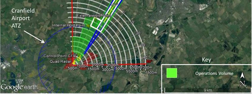
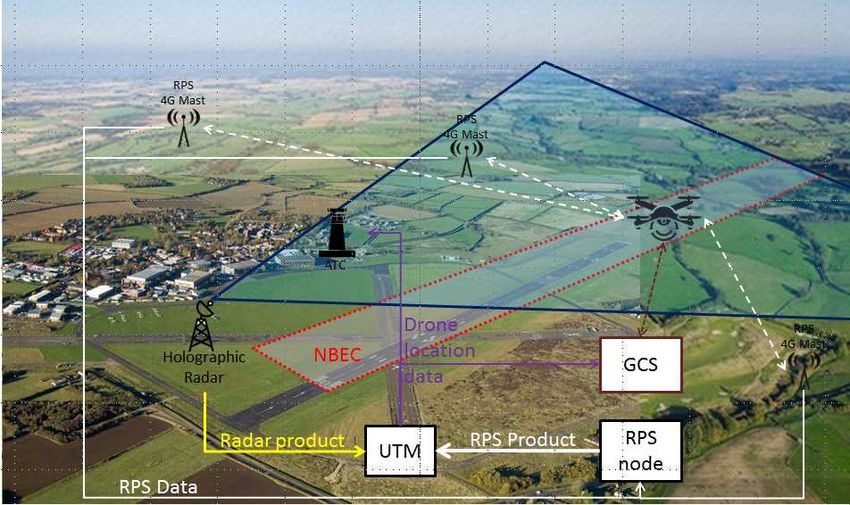
1. Introduction
A drone experimentation facility is being setup between Cranfield Global Research Airport and
Blue Bear Systems Research (BBSR) Twinwoods flight facility to develop and demonstrate
new capability whereby Unmanned Aerial Vehicles (UAS) and manned aircraft can jointly
operate Beyond Visual Line of Sight (BVLOS) in non-segregated airspace. The facility includes
ground infrastructure (radars, communications), procedures and airspace and has been named
National BVLOS Experimentation Corridor (NBEC). NBEC aims to provide the environment
in which a number of challenges can be addressed that currently prevent the large-scale roll-out
of UAS operations into manned aviation airspace. Firstly, the lack of system performance
requirements for the enabling communications, navigation and surveillance (CNS) ground
infrastructure for BVLOS operations. Unlike manned Air Traffic Services where these are well
established [1-2], these safety envelopes need to be quantified and then recommended and
endorsed by the National Supervisory Authority (e.g. CAA in the UK). Secondly, gaining
regulatory approval for BVLOS flights in non-segregated airspace requires a significant body
of evidence which can only be built if such flights are conducted in the first place, this has
created a long-standing catch-22 scenario.
NBEC addresses these two challenges by bringing together partners with complimentary
expertise, capability, experience and technology, and leveraging its Global Research Airport
ecosystem. NBEC has defined a phased approach using flight trials to test and characterise the
safety envelopes of the systems to be used in the ecosystem, and at the same time ensure safety
assurance mechanisms are followed during the testing phase, to increasingly gather evidence
and build confidence for the safe and expeditious integration of UAS BVLOS flights within
new and emergent airspace structures. Finally, NBEC investigates a holistic approach to deal
with rogue and intruding air vehicles entering the Airport operational environment
implementing thus cUAS functionality.
The remainder of the paper is organized as follows. Section 2 provides an overview of the drone
experimentation facility, its architecture, sensors and ground infrastructure; Section 3 presents
the capability development strategy. It presents the phased approach followed to incrementally
gather the appropriate evidence for the ecosystem’s individual components and inform the
safety, regulatory and performance requirements. Section 4 describes current progress:
identification of initial performance parameters and preliminary simulated sensor performance.
Finally, Section 5 summarises the salient points of the report and discusses future work.

2. Drone Experimentation Facility
2.1.Experimentation Volume
The initial NBEC volume consists of a narrow section of airspace extending from Cranfield’s
Airport Traffic Zone (ATZ) towards BBSR’s Twinwoods flight facility 10 miles away and from
surface to 400 feet AGL (see Fig. 1). The corridor follows the approach / departure route to the
Cranfield main runway; in order to de-conflict with manned aviation traffic, the corridor “dog
legs” to the west (approaching the airport). Provision for an aircraft (drone) ‘hold’ has been
made either side of the Cranfield ATZ boundary. The volume has been developed to allow
sufficient ‘down range’ for NBEC’s radar and ‘hold points’ either side of the ATZ boundary to
allow airspace management requirements to be taken into account.
The drone experimentation facility is shown in Fig. 2 and consists of a 3D Holographic radar,
a Radio Positioning System (RPS), an Unmanned Traffic Management (UTM) system that

2
integrates to Air Traffic Control (ATC) and its ADS-B capability. Note that Fig. 2 illustrates
only the initial NBEC footprint, i.e. within ATZ, whilst the actual corridor is 10 miles long.

                                   Figure 1. NBEC Test Volume.

                        Figure 2. Drone Experimentation Facility Components.

2.2. Aveillant Holographic Radars
To provide a non-cooperative target surveillance capability to the overall ecosystem, a 3D
holographic radar system is installed. Initially, the Gamekeeper 16U is employed, which will
eventually be replaced by the longer range ‘QUAD’ demonstrator radar (see Fig. 3). Both are
advanced 3D holographic radars developed by Aveillant Ltd and are deployed to provide
situational awareness in terms of the localization of all airspace users within the range of the
systems. With no moving parts, holographic radars consist of a 2D receiver array that
continuously "floodlights" the entire field of view, resulting into longer coherent integration
times and thus providing 3D position and very high Doppler resolution at a high update rate.
                                                                                              3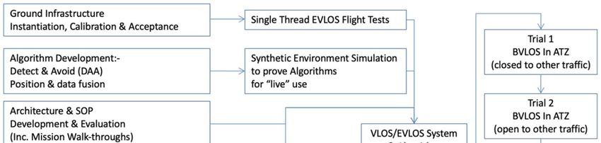
These radar characteristics are crucial for better detection, discrimination and tracking of small,
slow, but manoeuvrable targets, such as UAS and other Class G targets, even against stationary
clutter and ground targets. The Gamekeeper [3, 4] has been specifically designed for high
performance detection of drones and has been deployed at numerous airfields worldwide.
Previous work has documented its sensitivity against typical drone targets [5]. Table 1 lists the
operating parameters for the Gamekeeper 16U and QUAD sensors.

                          Gamekeeper radar                                          QUAD radar

                                       Figure 3. Aveillant Holographic Radars.

                              Table 1. Gamekeeper 16U and QUAD Radar parameters
                          Parameter                 Gamekeeper Value               QUAD Value
                  Frequency                              L band                      L band
                  Bandwidth                             ~2 MHz                       ~2 MHz
                  Transmit power                         >1 kW                       >12 kW
                  Receiver channels                      4 x 16                     4 x 8 x 16
                  Azimuth coverage                         90°                      Up to 90°
                  Elevation coverage                       30°                      Up to 60°
                  Update rate                         ~0.25seconds                Configurable
                  Drone detection range                  7.5 km                10 km (expected)

2.3. Vodafone Radio Positioning System
RPS provides real-time location of a mobile device by using the ubiquitous Mobile Radio
Network information and thus, not relying on having GPS reporting capability (or GPS
coverage) on the device. The technology can display information on the quality of the mobile
connection plus the reported GPS location, estimated RPS location and the accuracy confidence
value simultaneously for drones used for the trial in real time. Moreover, RPS can be used to
improve current services (e.g. network optimisation tools and emergency calls accuracy). Table
2 provides a summary of its performance parameters [6,7]. It is used to demonstrate that cellular
networks can: (i) be used to identify and distinguish between different UAS; (ii) estimate the
location of the UAS independently of GPS telemetry, thus providing a means to verify such
telemetry and flag up cases where the GPS location may be being spoofed; and (iii), when
required, transmit flight commands to UASs allowing for modifications of flight plans.
                                        Table 2. Vodafone’s RPS parameters
                                          Parameter                                       RPS Value
                                          Latency (from mobile network)1                   40-50 ms
                                          Update rate                                     2 Hz (0.5 s)
                                          Horizontal accuracy                              +/- 150 m
                                          Theoretical limit                                 +/- 60 m

1In the case of operating a single UAS, the time taken between the mobile network data being sent and a location estimate
being produced is around 100 ms which is comparable to GPS,
4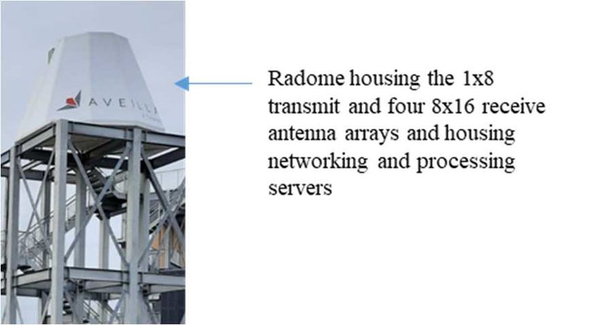
2.4. Unmanned Aircraft Systems Traffic Management
A UTM is installed to provide a composite situational awareness display to the operator (or
service provider) by acting as the host for the fusion algorithms and outputs from the various
navigation and surveillance technologies. Information is collected and analysed to determine
the viability of different solutions and algorithms used to support drone operations in both
normal operating and contingency circumstances. The UTM will carry out:-
    • Pre-flight flight plan de-confliction and approval, including liaison with local ATC and
        [Simulated] mission de-confliction with all UAS operations;
    • In flight route management, including UAS operation Situational awareness display,
        Adherence to published plan, Ground-based DAA (GBDAA) function, local ATC
        liaison and connectivity with UAS operator.

2.5. Integrated Link to Air Traffic Control
For the controlled airspace integration, the drone experimentation facility include a link with
manned aviation and ATC. Cranfield University has its own Airport, ATC, aircraft (manned
and unmanned) and pilots and thus provides a unique sandbox, where concepts, systems and
solutions can be tested and validated in a controlled manner in an safe operational environment,
obtaining direct feedback from the various stakeholders. To supplement the ATC capability, a
new ADS-B workstation was installed for enhanced situational awareness to allow controllers
to receive clear identification of any dronesand manned aircraft in the controller airspace which
are fitted with a compliant ADS-B transmitter. A dedicated Radar Display Position is currently
being procured to further extend the separation and deconfliction capability of the controllers.

2.6. Data Provision
For each flight, data is collected from (up to) four independent systems: (i) the holographic
radar(s), (ii) the RPS, (iii) the Cranfield Airport’s ADS-B system and (iv) the drone’s GPS and
flight data. Other technologies are being considered for future inclusion (e.g. acoustic sensing).
In addition to these data samples, atmospheric conditions will be recorded prior to each trial
session, with this information gathered at Cranfield Airport. Table 3 presents the data gathered
by each of the four sources and the frequency at which they are logged. These will be used to
charctaerise the various safety envelopes for each of the facility components described above.

                                    Table 3. Trial Data Logging
 Data Source                         Data set                         Sample        Data Format
                                                                     Frequency
   Drone     Timestamp, Position and altitude estimates 30 Hz                       BBSR
  Telemetry  (lat/long/alt WGS 84 for position and AMSL in                          Standard
             meters for altitude), Speed estimates in 3 dimensions                  Protocol
             (for dead reckoning if required), dilution of precision
    RPS      Can be customised but as a minimum time, lat, long, 2 Hz               JSON file
             altitude, horizontal dilution of precision
 Holographic Time of measurement, Track Identification, Target 4 Hz                 ASTERIX
   Radar     type, 3D position, velocity, track status                              CAT34/48
   ADS-B     Time, identification, current position, altitude, 2 Hz                 ASTERIX
             velocity                                                               CAT21

                                                                                                5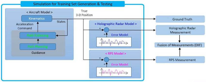
3. Experimentation Capability Development
3.1. Development Strategy
The test strategy consists of gathering sufficient evidence incrementally to support an
operational approval by the CAA’s regulatory team to enable routine non-segregated BVLOS
flights in uncontrolled (Class G) airspace. The test plan focuses primarily on incorporating a
DAA ecosystem solution in order to support the flight trial series, addressing the CAA’s
requirements [8]. To achieve a compliant DAA solution not only is there the technical system
automation / autonomy development element, but also the integration with extant manned
aviation traffic management systems, processes and procedures. This integration approach will
be assessed initially with minimal automation in the UAS management architecture so that the
processes and procedures can be fully understood by Air Traffic Controllers including their
ability to manage UAS within the ATZ with required response timeliness and accuracy
established. The individual test strategy activities are depicted in Fig. 4 and are described below.
To support the trials, the ground infrastructure elements, described in section 2, are deployed
in the most suitable position to maximise their coverage and ensure safe flight operations. Each
element will go through its own calibration needed for its commissioning, that includes testing
through a comprehensive series of visual line of sight (VLOS) / extended visual line of sight
(EVLOS) flights (denoted as the single thread flight tests in Fig. 4) designed to support its
operational readiness. Those data are captured to formulate their initial performance envelope.
Positional information of UAS (and indeed of all airspace users) is required to support the
NBEC airspace management, and thus to provide resilience and avoid any single-point-of-
failure. For this purpose, the ecosystem fuses positional information from the radars and other
independent data sources. An assessment of these algorithms will be carried out to assess the
accuracy to which they can derive UAS (and/or other airspace users) position not only when all
data sources are available, but also as source data degrades and/or ceases.

                               Figure 4. The streamline of the trials / tests

A synthetic environment is developed to carry out assessments of the positioning data fusion
and GBDAA prior to being flown in the ‘real world’ (see Fig. 5). This allows a wide selection
of use cases to be modelled, with different operational situations and solution variants,
including failure cases, reversionary / contingency planning and adverse meteorological
conditions. This ensures robustness testing using numerous simulated “threats” thus allowing

6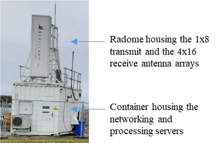
the system to be stressed without eroding safety margins or increasing risk. Once the entire
ecosystem is commissioned and integrated, initial VLOS / EVLOS integration flight tests will
be conducted on the same four BVLOS profiles and configuration to prove the flight
management processes derived to enable UAS to safely operate within those airspace volumes
and to gather DAA performance data. This will finally enable entry into the final BVLOS trials
phase, which consists of 4 trials as shown in Fig. 4.

                    Figure 5. Initial Synthetic Environment for algorithms validation

3.4. Counter drone capability development
Existing approaches to deal with rogue and intruding drones at airports have been disparate as
drone detection technologies do not yet have institutionalised regulatory requirements. This is
because the majority of these systems have been installed for business continuity and security
reasons, rather than safety, following major disruptive events at airports such as Gatwick, and
Frankfurt [9]. There are currently over 500 counter UAS (cUAS) solutions, which use different
techniques [10], none of which is optimal on its own and most airports have a combination of
sensors and procedures to mitigate against these threats. The Gamekeeper radar has been
installed at major Airports such as London Heathrow, where it forms part of a drone detection
and mitigation solution that includes other sensors. This project takes a holistic approach to
cUAS by providing a fused output that leverages and combines sensor capability and
performance (as per Fig. 5). The trials strategy will gather evidence to produce performance
requirements as well as recommended methods (e.g. sensors, procedures, responses, etc.) to
detect and mitigate against rogue drone threats. Comparison of all sensors will be conducted in
order to ascertain the best method to deal with those threats.

4. Progress and Challenges
The first project outputs have been the submission of the BVLOS within the ATZ Operational
Safety Case and the CAA’s BVLOS DAA Ecosystem exposition, which includes initial target
performance (Table 4) and the DAA mitigation strategies (Table 5).
                Table 4. Initial Target Performance requirements (from Manned Aviation)

                                                                                             7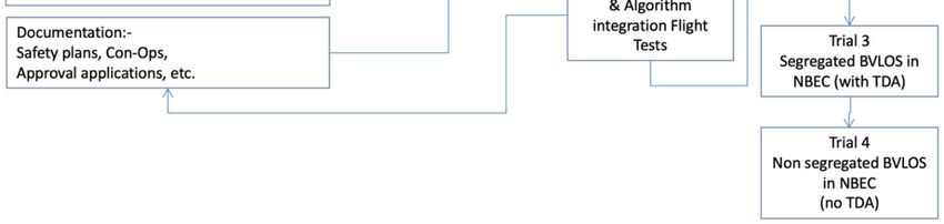
Requirement for 3 NM separation        Non-cooperative sensor            Cooperative sensor
    Nominal refresh period                 ≤5 seconds                        ≤5 seconds
    Probability of position update (per    ≥90%                              ≥97%
    aircraft in global coverage)
    Horizontal position RMS error          ≤300 m in global coverage         ≤300 m global and ≤330 m
                                                                             for 100% of the flights
    Average data age                       ≤2.5 seconds                      ≤4 seconds
    Continuity (probability of critical    ≤2.5 10-5      per   hour    of ≤2.5 10-5 per hour of operation
    failure)                               operation
    Probability of update of aircraft      N/A                               ≥98% global
    identity with correct value
    Delay of change in aircraft identity   N/A                               ≤15 s for 100% of the cases
    Resolution                             Ability to resolve two aircrafts at 1 NM, with a probability of
                                           greater than 95%

There are currently no specific performance requirements set for BVLOS, ground infrastructure
or DAA for UAS and UTM, and thus the first baseline NBEC adopted was based on existing
manned aviation requirements [1, 2], understanding that these would be ratified as evidence is
gathered. For reference, Table 4 provides a sample of the requirements for the 3 NM separation
provision, which are compared to Tables 1 and 2 that describe the infrastructure (radar and
RPS) anticipated performance, based on previous analyses. to provide further insights on
potential sensor performance, simulations were carried out using the synthetic environment
shown in Fig. 5, as it is expected that these safety envelopes will be tightened as the kinetic
characteristics of small drones are lower than commercial aircraft. Initial error figures were
obtained as shown in Table 5 for the fused measurement output (through a simple Extended
Kalman Filter), which as expected provide over 30% improvement in performance compared
with the individual sensor performance. These simulated results will be validated by the flight
trials programme mentioned in the previous section.
                    Table 5. Expected performance of fused positioning based on simulations
                                Mean Error (m)          Standard Deviation of Error (m)
                       E           -0.9235                          8.7375
                       N           -2.2386                         35.6729
                       U            0.4706                         23.4983

The DAA mitigation strategies for each trial have been defined in Table 6. These provide safety
assurance that the trials can be conducted, as well as providing a security mechanism to develop
cUAS strategies by combining sensor capabilities to identify rogue and intruding aircraft.

8
Table 6. DAA mitigation strategies
Evidence Trial 1 BVLOS in (closed) ATZ Trial 2 BVLOS in (open) ATZ Trial 3 Segregated BVLOS in Trial 4 Non-segregated BVLOS in
NBEC (with TDA) NBEC (no TDA)
Mitigations ATZ active and staffed but ATZ active and staffed. ATZ ATZ closed to all other traffic. ATZ closed to all other traffic. UAS
closed to all traffic except closed to non-cooperative traffic. UAS only area defined for BVLOS only area defined for BVLOS flight
NBEC UAS. ATZ closed to visiting traffic. ATZ flight envelope. Issue NOTAM. envelope. Issue NOTAM. NBEC
open to pre-approved specific NBEC 'airspace' segregated by 'airspace' non-segregated and
Cranfield-based cooperative traffic. means of TDA and monitored for monitored for coop and non-coop
coop and non-cooperative aircraft. aircraft.
Cooperative NOTAM issued, ATC open to Only Cranfield-based manned NOTAM issued for Sterile (pre-
NOTAM issued for Sterile (pre-
(coop) Aircraft respond to radio calls from coop aircraft operating. Mandate that defined, NOTAM’d) UAS-only
defined, NOTAM’d) UAS only
(Manned) aircraft and to monitor positions only those ADS-B equipped can section of ATZ and NBEC
section of ATZ and NBEC 'airspace'.
of those that are ADS-B operate. ATC monitors segregation 'airspace'. ATC monitors
ATC monitors volume through
equipped. Local Operators brief through receipt of ADS-B info. segregation through receipt of
receipt of ADS-B information.
in advance. Local Operators briefed in advance. ADS-B information.
Cooperative All UAS ADS-B equipped (EC All UAS ADS-B equipped (EC
All UAS ADS-B equipped (EC approved spec). UAS fitted with RPS as
Aircraft approved spec) approved spec). UAS also fitted
backup system (expect to have reduced accuracy vs ADS-B).
(Unmanned) with Vodafone RPS for evaluation.
Non- NOTAM issued. Non-compliant ATZ closed to NC2 aircraft.
cooperative/ Local Operators briefed in Accuracy of Holographic Radars RP monitors NC2 aircraft position RP monitors NC2 aircraft position
non- advance. feeds to be identified in advance and velocity detected using and velocity detected using
communicative using LOS/EVLOS flight. Non- Holographic Radar, to a known Holographic Radar, to a known
(NC2) Aircraft compliant Local Operators briefed accuracy. accuracy.
in advance.
Tactical RP has visibility of UAS location from GCS (GPS derived). ATC has RP has visibility of UAS location from GCS (GPS derived), and other
Collision visibility of UAS location from ADS-B received (GPS derived). traffic from Holographic radar feed. ATC has visibility of UAS location
Avoidance from ADS-B received (GPS derived). UAS restricted to specific area
through use of Geofencing. ATC has visibility of all aircraft together with
their position and velocity within ATZ and NBEC, to known accuracies.
UAS restricted to Sterile (pre-
defined, NOTAM’s) area through
use of Geofencing.
The International Radar Symposium IRS 2021, June 21-23, 2021, Berlin, Germany
9
978-3-944976-30-3 ©2021 DGON5. Conclusions
This paper describes the current progress in development of the drone experimentation facility
and enabling ecosystem - NBEC, identifying some of the main challenges that it will address.
The ecosystem intends to establish the building blocks underpinned by a trials strategy with
incremental evidence gathering to demonstrate safe integration of manned and unmanned
aircraft, enable routine BVLOS operations in non-segregated airspace and subsequently allow
it to become a trials facility available for other users. The NBEC is a modular and ‘plug and
play’ ecosystem, where new concepts, systems and solutions can easily be integrated and tested
(at scale if necessary) in a real operational environment. The ecosystem provides along with the
DAA also cUAS capabilities that combine radar and supplementary sensor functionalities to
detect and identify rogue and intruding air vehicles.
A synthetic environment that accurately represents the real-life sensor architecture (radar and
RPS at this stage) and includes a fusion capability provides preliminary results that supports
the performance validation activity, ahead of the real flight trials.
The consortium works closely with the UK CAA’s Innovation Hub, to ensure that the solutions
and services developed to address these challenges are future proofed and aligned with extant
and emerging regulations. Close collaboration with NSAs is fundamental, as well as ensuring
lessons learnt, results and best practices are discussed and shared with the industry.
References
[1] CAA CAP670 Air Traffic Services Safety Requirements June 2019.
[2] EUROCONTROL Specification for ATM Surveillance System Performance (Volumes 1 & 2),
Ed. 1.1. September 2015.
[3] M. Jahangir and C. J. Baker, “Persistence Surveillance of Difficult to Detect micro-drones with
L-band Holographic Radar”, CIE 2016 IRS, Guangzhou, China, October 2016.
[4] M. Jahangir and C. J. Baker, “Characterisation of low observable targets with a multi-beam
staring radar”, IET Radar 2017, Belfast, UK, October 2017.
[5] M. Jahangir and C. J. Baker, “L-band staring radar performance against micro-drones”,
International Radar Symposium (IRS) 2018, Bonn, Germany, June 2018.
[6] Vodafone, “Beyond Visual Line of Sight Drone Trial Report”, November 2018.
[7] Vodafone, “Network-Based Drone Airspace Management Trial Report”, December 2019.
[8] CAA Innovation Hub CAP1861A, “Detect & Avoid Ecosystem for BVLOS in Non-Segregated
Airspace”, October 2020.
[9] G. Lykou, D. Moustakas, D. Gritzalis, "Defending Airports from UAS: A Survey on Cyber-
Attacks and Counter-Drone Sensing Technologies" Sensors 20, 2020.
[10] A. H. Michel, ``Counter-drone systems'', Center Study Drone Bard College, Bard College, NY,
USA, December 2019.
[11] K. Honggu, J. Jingon, K. Jinyoung, K. Joonhyuk, S. C. Tong, "Protect your sky: A survey of
counter unmanned aerial vehicle systems." IEEE Access 8 (2020).
The International Radar Symposium IRS 2021, June 21-23, 2021, Berlin, Germany
10
978-3-944976-30-3 ©2021 DGONYou can also read