Development of Bridge and Lever Type Compact Compliant Mechanism for Micro Positioning Systems
←
→
Page content transcription
If your browser does not render page correctly, please read the page content below

Journal of Physics: Conference Series

PAPER • OPEN ACCESS

Development of Bridge and Lever Type Compact Compliant Mechanism
for Micro Positioning Systems
To cite this article: Parag Marathe et al 2021 J. Phys.: Conf. Ser. 1969 012006

View the article online for updates and enhancements.

                               This content was downloaded from IP address 46.4.80.155 on 27/08/2021 at 12:05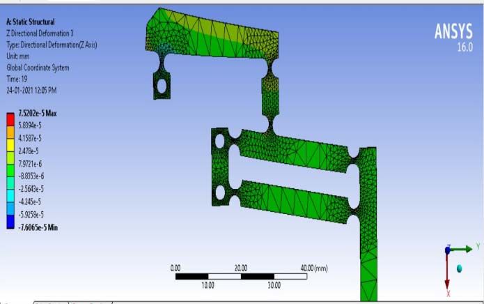
IRMAS 2021                                                                                                      IOP Publishing
Journal of Physics: Conference Series                         1969 (2021) 012006          doi:10.1088/1742-6596/1969/1/012006

Development of Bridge and Lever Type Compact Compliant
Mechanism for Micro Positioning Systems

                     Parag Marathe1*, Sujit S. Pardeshi1,and Bhagyesh Deshmukh1
                     1
                       Department of Mechanical Engineering, College of Engineering Pune, Pune,
                     Maharashtra, India
                     2
                       Department of Mechanical Engineering, Walchand Institute of Technology, Solapur,
                     Maharashtra India

                     *Corresponding Author: Parag Marathe, Email: paragmarathe9@gmail.com

                     Abstract. Nowadays, for precision positioning applications (Micro-Electro-Mechanical
                     Systems, Nano/Micro positioning devices), compliant mechanisms are extensively used over
                     traditional mechanisms. Compliant mechanisms are joint less mechanism having merits as no
                     wear and friction, no backlash and no lubrication. In this paper, a newly developed flexure
                     hinge based bridge and lever type compact compliant mechanism has been proposed for the
                     precision linear displacement applications. This mechanism can be used in the portable
                     cameras for image stabilization, lens shutters, alignment and levelling devices, etc. The key
                     performance parameters for developing the compliant mechanism are the input
                     displacement/force, output displacement and amplification ratio. For designing compact
                     amplified compliant mechanism (CACM), Pseudo-Rigid-Body-Model (PRBM) method is
                     used. The finite element analysis of developed micro-displacement amplifier compliant
                     mechanisms carried out by using ANSYS workbench. The analyses and experimentation is
                     performed for the input displacement, output displacement and amplification ratio of
                     mechanism. An input force range considered for analysis is in between 1 N to 50 N. All the
                     results from analytical, simulation and experimentation are compared. The error in output
                     displacement is observed up to 6% and the geometric amplification ratio for the mechanism is
                     observed up to 6.5.

1. Introduction
Compliant mechanisms are extensively used over the traditional mechanism due to advantages like no
lubrication required, no backlash, no friction. Also due to monolithic structure, a compliant
mechanism saves assembly time. Many researchers and professionals working on these mechanisms,
and explores plenty of designs according to need and application. In this literature, many in plane
micro positioning flexure mechanisms are reviewed. For example, Yang li [1] developed a structure
from material Al7075, of size 140 mm x 140 mm x 7 mm. This mechanism delivers maximum
displacement of output stage is 64.2 µm. The geometric amplification of the mechanism is 3.7. Also
JaroslavHricko [2] designed a compact compliant gripper mechanism of size 154.2 mm x 80 mm x 3
mm using polyamide material. A displacement delivered at the gripper tip by the mechanism is 8.5
mm. The amplification ratio achieved is up to 4.6. Guimin Chena [3] designed elliptical hinge based
displacement amplifier compliant mechanism of overall size approx. 210 mm x 150 mm x 5 mm. The
mechanism is made from the acrylic glass sheet and delivers 3 mm maximum output displacement.
The amplification ratio achieved is up to 33.6 and Yangmin Li [4] designed and developed the flexure
based parallel micro positioning stage from Al-7075 Alloy of overall dimensions are 75 mm x 75 mm
              Content from this work may be used under the terms of the Creative Commons Attribution 3.0 licence. Any further distribution
              of this work must maintain attribution to the author(s) and the title of the work, journal citation and DOI.
Published under licence by IOP Publishing Ltd                          1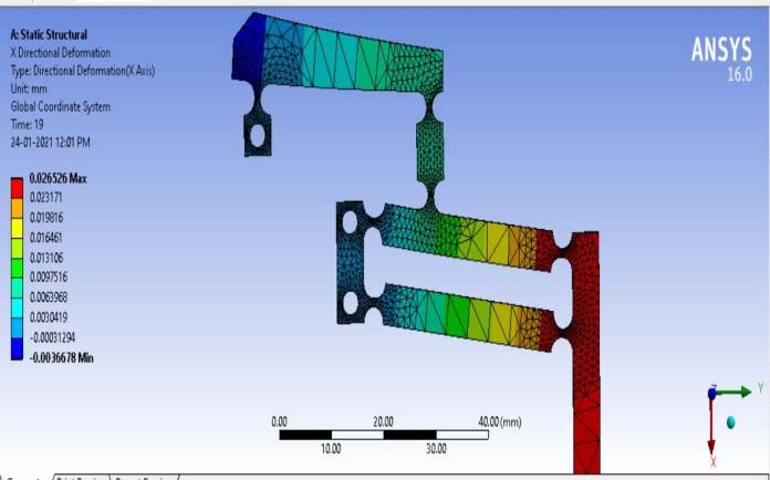
IRMAS 2021                                                                              IOP Publishing
Journal of Physics: Conference Series        1969 (2021) 012006   doi:10.1088/1742-6596/1969/1/012006

x 6 mm. The capacity of output displacement of mechanism is 15.74µm. The amplification ratio
achieved is 3.7.
    To design compliant mechanisms, there are various methods [5] such as Pseudo Rigid Body Model
(PRBM), Inverse Methods, structural optimization technique etc. In this paper, a bridge and lever type
compact compliant mechanism is designed by Pseudo Rigid Body Model (PRBM) method. In PRBM,
Flexure hinge of the mechanism is replaced by the torsion spring with equivalent stiffness and
modeling is done by considering the classical rigid body model equations.According to need and
applications, the first objective is to design and develop a compact sized compliant mechanism for
linear displacement application and second is to enhance the Geometric Amplification (GA) ratio. The
paper is organized as follows, after the briefing introduction, literature and objectives; section 2
describes the modeling of bridge and lever type compact compliant mechanism followed by the
Section 3 as FEA analysis of optimized compliant mechanism. In section 4, an experimentation
procedure is explained. In last results are plotted and draws some conclusions.

2. Modelling of Compact Amplifier Compliant Mechanism
A bridge and lever type compact compliant mechanism is shown in figure 1 (a). To carry out the
PRBM, the hinges of the mechanism are replaced with the torsion springs as shown in figure 1 (b).

                        (a)                                          (b)
      Figure 1: (a) Proposed Compact Compliant Mechanism; (b) PRBM of Compact Compliant
                                          Mechanism

    A right circular flexure hinges are used for mechanism [6]. The compliance ratio of right circular
hinges depends on the flexure hinge neck thickness (t) and radius of flexure hinge (r). Here t/R is
considered as 0.5 ease of manufacturing.
    The equation of stiffness of the circular hinge is,
                    .
                .                                                                                (1)
where,
w = mechanism thickness
r = flexure hinge radius
t = Flexure hinge notch thickness
l = overhang distance of lever
                 ∗                                                                               (2)
Rearrange the equation 2 as,
            ∗
                                                                                                 (3)
     The dimensions considered for the analysis are overhang distance of lever (l) is 5mm, thickness
of mechanism (w) is 1.5 mm, neck thickness of flexure hinge is 1mm and radius is considered as 2mm
for the analysis.

                                                   2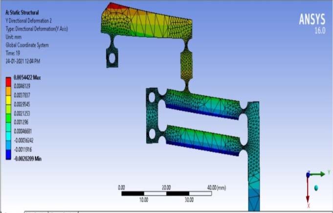
IRMAS 2021                                                                                     IOP Publishing
Journal of Physics: Conference Series           1969 (2021) 012006       doi:10.1088/1742-6596/1969/1/012006

     The output displacement of mechanism can be calculated by using the equation 4.
                                                                                                        (4)
A carbon steel material is selected due to its higher       value [7].
As this value is higher, it gives high rigidity and natural frequency. Following table shows the
mechanical properties considered for further analysis.

                                  Table 1.Material (Carbon Steel) Properties
                           Parameter                 Unit            Value
                           Yield stress (Syt)        MPa             250
                           Poisson's Ratio (μ)       ----            0.3
                           Density (ρ)               Kg/m3           7850
                           Young Modulus (E)         GPA             200

3. Optimized FEA Model
A simple rectangular shaped lever of the mechanism shows bending. To prevent such bending
deformation of beam, a triangular shaped beam is adopted as shown in following figures. The
simulation result of mechanism at 50N input force is shown in figure 2.Figure 2 (a) shows the
maximum displacement of motion stage as 26.5µm in desired direction. An error motion in
mechanism is shown in figure 2 (b) and (c) as 0.06µm and 0.005µm in Y direction and Z direction
respectively. Last figure (d) shows the stress distribution in the mechanism. A maximum stress
developed is 71.9MPa.

                            (a)                                                     (b)

                            (c)                                           (d)
         Figure 2. Simulation results of mechanism (a)X directional deformation, (b) Y directional
                Deformation, (c) Z directional Deformation and (d) Equivalent Stress.

                                                        3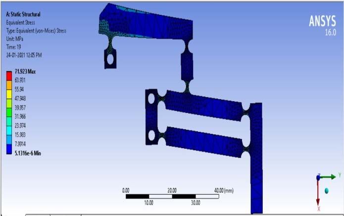
IRMAS 2021 IOP Publishing
Journal of Physics: Conference Series 1969 (2021) 012006 doi:10.1088/1742-6596/1969/1/012006
4. Experrimentation n of Mechaniism
Experimmentation is performed
p to compare analytical
a an
nd simulatioon results. The block diaagram of
experimeental set up is
i shown in figure
f 3.The mechanism is actuated by
b the linear precision miicrometer
based actuator.
a An applied foorce can be recorded using
u Arduiino controlliing unit. An
A output
displacemment value for
f corresponnding input force has beeen recordedd by using diigital dial gaauge with
LC 0.0001mm.The annalytical results obtainedd for the forrce range 1N
N to 50N arre compared with the
simulatioon and the experimentaal results. A comparativ ve representtation of Inpput force vss. Output
displacemment is show
wn in figure 4.
4 The numerical data is given in Apppendix.
Figgure 3.Blockk Diagram off Experimenttal set up
5. Resullt and discusssion
Simulatiion and expeerimentation results are examined
e forr the displaccements. Thee output disp
placement
results arre plotted w..r.t input forcce.
It has beeen observed that,
The maximum
m displacement in i the desiredd direction iss 26.5 µm whhen input forrce is 50N.
The parasitic
p erroor motion vallues of motioon stage at th he same forcce are approxximately 0.066µm in Y
directtion and 0.0005µm in Z direction
d whiich are negliigible. It meaans that the movement of o motion
stage is perfectly linear.
The maximum
m sttress developped in the mechanism
m iss around 72 MPa when 50N load iss applied.
Thereefore the mecchanism is safe for maxim mum operatiing conditionns.
The Geometric amplificationn (GA) ratiio achieved for plain carbon c steell material iss 7.2 by
simullation and 6.5 is by expperimentationn. It is twicee than the exxisting mechhanisms prop posed by
various researcheers.
The overall
o size of
o developedd compliant mechanism is 70 mm X 50mm X 1..2 mm. thereefore it is
calledd as compactt.
The variation
v in the
t output vaalues of dispplacement by y simulation and experim mentation is up
u to 6%.
This variation in the result occurs
o due too the variatiion in materiial structure, errors asso
ociated in
buildding the setuup (Alignmennt error) andd error assocciated with the instrumeents used fo or testing.
Also human erroors associateed during thhe actuation of mechaniism and recoording the values v of
displaacements.
4IRMAS 2021 IOP Publishing
Journal of Physics: Conference Series 1969 (2021) 012006 doi:10.1088/1742-6596/1969/1/012006
Figure 4. Comparative representation of Input force and Output Displacement
6. Conclusion
A compact model of compliant mechanism has been developed using PRBM and results are
corroborated with the simulation and experimental results. The design and modelling get simplified
due to the use of spring (energy) equation in the PRBM. The developed mechanism has been tested for
the force range of 1N to 50N; it has been observed that the maximum stress level is within the range of
Syt. Results values of displacement obtained by the FEA simulation are in close range with the values
by experimental result. Therefore FEA analysis is important prior to the experimentation. Both Lever
type and Bridge Type of mechanism used in combination successfully, which compiles the
characteristics of both mechanisms and forms stiff and compact size mechanism. Such mechanisms
can be used for MCB’s, electric switches for multiple connections also used for micro levelling and
micro positioning devices.
References
1. Li, Y., BohuaYin, B., Liu, J., Jin, P. (2017). Optimal Design of Micro/Nano Positioning Stage with Wide
Range and High Speed Based on Flexure Structure. IOP conference series: Materials Science and
Engineering, 2017, 274.
2. Hricko, J., Havlik, S. (2015). Design of Compact Compliant Devices – Mathematical Models vs.
Experiments.American Journal of Mechanical Engineering, Vol. 3, No. 6, 201-206.
3. Chena, G, Mab, Y, Lia, J (2016). A tensural displacement amplifier employing elliptic-arc flexure
hinges,Sensors and Actuators,A 247, 307–315.
4. Li, Y., QingsongXu Q. (2011). A Totally Decoupled Piezo-Driven XYZ Flexure Parallel Micropositioning
Stage for Micro/Nanomanipulation.IEEE Transactions On Automation Science And Engineering, Vol. 8, No.
2.
5. Howell L.L. (2001). Compliant mechanisms. New York, NY: John Wiley & Sons.
6. Deshmukh, B., Pardeshi, S., Mistry, R., Kandharkar, S., Wagh, S. (2014). Development of a Four bar
CompliantMechanism using Pseudo Rigid Body Model (PRBM).Procedia Materials Science,6, 1034 – 1039.
5IRMAS 2021 IOP Publishing
Journal of Physics: Conference Series 1969 (2021) 012006 doi:10.1088/1742-6596/1969/1/012006
7. Patil, V. S., Anerao, P. R., Chinchanikar, S. S. (2018). Design and Analysis of Compliant Mechanical
Amplifier, ICMMM - 2017, Materials Today: Proceedings, 5, 12409–12418.
8. Pardeshi, S., Kandharkar, S., Deshmukh, B. (2017). Monolithic compliant slider crank mechanism for motion
amplification, Materials Today: Proceedings, 4, 1677–1682.
Appendix A
A.1. Result values of Input Displacement, Output displacement and Amplification Ratio
Force Equi. FEA Simulation Experimental (Expt.) Geometric
(N) (Von Amplification (GA)
Mises) Ratio
Stress Input Disp. Output Disp. Input Disp. Output FEA Expt.
(MPa) (mm) (mm) (mm) Disp. (mm)
1 1.4385 7.34*E-05 5.31*E-04 - - 7.23 -
2 2.8769 1.47*E-04 1.06*E-03 - - 7.23 -
3 4.3154 2.20*E-04 1.59*E-03 - - 7.23 -
4 5.7538 2.93*E-04 2.12*E-03 - - 7.23 -
5 7.1923 3.67*E-04 2.65*E-03 - - 7.23 -
6 8.6307 4.40*E-04 3.18*E-03 - - 7.23 -
7 10.069 5.13*E-04 3.71*E-03 - - 7.23 -
8 11.508 5.87*E-04 4.24*E-03 - - 7.23 -
9 12.946 6.60*E-04 4.77*E-03 - - 7.23 -
10 14.385 7.34*E-04 5.31*E-03 - 5.00*E-03 7.23 -
15 21.577 1.10*E-03 7.96*E-03 - - 7.23 -
20 28.769 1.47*E-03 1.06*E-02 - 1.00*E-02 7.23 -
25 35.961 1.83*E-03 1.33*E-02 - - 7.23 -
30 43.154 2.20*E-03 1.59*E-02 2.50*E-03 1.50*E-02 7.23 6.00
35 50.346 2.57*E-03 1.86*E-02 - - 7.23 -
40 57.538 2.93*E-03 2.12*E-02 3.00*E-03 2.00*E-02 7.23 6.67
45 64.73 3.30*E-03 2.39*E-02 - - 7.23 -
50 71.923 3.67*E-03 2.65*E-02 4.00*E-03 2.50*E-02 7.23 6.25
* As the movement of Input link and Output link are in opposite direction, so output displacement carries
negative sign but real values are considered for calculation.
**An experimental Input displacement values are measured by using the optical microscope and sylvac digital
dial gauge of LC0.001mm.
6You can also read