Dissolved Oxygen Sensor - User Manual - Model: S-RJY-01 Version: V1.0
←
→
Page content transcription
If your browser does not render page correctly, please read the page content below
Dissolved Oxygen Sensor - User Manual
Model: S-RJY-01

Version: V1.0

                                         页   共        4        页
                ©        0        Se e           ch       ol       y   o   t   Al   i   s
                ww           tu   o
                     d
User Manual
Table of contents
1. Background meaning and working principle..................................................................................................... 3
1.1 Background meaning ............................................................................................................................ 3
1.2 Working principle ................................................................................................................................. 3
2. Technical Parameters ......................................................................................................................................... 4
3. Dimensions ........................................................................................................................................................ 5
4. Product installation and wiring ......................................................................................................................... 6
5. RS485 communication...........................................................................................................................................7
5.1 Frame format ........................................................................................................................................ 8
5.2 Register address .................................................................................................................................... 9
5.3 Command example ............................................................................................................................ 1 1
5.4 Error response ..................................................................................................................................... 12
5.5 Use the serial port debugging software to communicate ............................................................... 1 3
6. Maintenance......................................................................................................................................................... 1 4
6.1 Use and Maintenance .......................................................................................................................... 1 4
6.2 Calibration .......................................................................................................................................... 1 4
第 2 页 共 14 页
©2008-2023 Seeed Technology Co., Ltd. All rights reserved. www.seeedstudio.coUser Manual
1. Background meaning and working principle
1.1 Background meaning
Dissolved oxygen (DO) refers to the content of oxygen dissolved in water, which is expressed in
milligrams of oxygen per liter ofwater, and dissolved oxygen exists in water in a molecular state. The
amount ofdissolved oxygen in water is one ofthe important indicators ofwater quality and one ofthe
important factors ofwater purification.
The content of dissolved oxygen in water is related to factors such as atmospheric pressure, water
temperature and salinity. For water bodies not polluted by oxygen-depleting substances
(generally organic matter), the dissolved oxygen is saturated, for example, the dissolved oxygen in
clean surface water is close to saturation. When there is a lot of organic matter in the water
body, the oxygen consumption rate exceeds the oxygen supply rate, and the dissolved oxygen in the
water will continue to decrease, even close to zero, so that the organic matter will decompose under
the anoxic condition, and the phenomenon of corruption and fermentation will occur, making the
water quality serious. deterioration. Therefore, in the quality evaluation of water bodies, dissolved
oxygen is used as an indicator ofthe degree ofwater pollution.
1 .2 Working principle
S-RJY-01 integrated online fluorescence method dissolved oxygen sensor is designed based on the
principle ofquenching excitation fluorescence by specific substances in physics. When the excitation
light is irradiated on the fluorescent substance on the surface of the fluorescent
film head, the fluorescent substance is excited and emits fluorescence, and the extinguishing time
ofthe fluorescence is affected by the concentration of oxygen molecules on the surface ofthe
fluorescent film head. The concentration of oxygen molecules can be calculated by detecting the
phase difference between the fluorescence and the excitation light and comparing with the internal
calibration curve, and the final value is output after temperature compensation.
No electrolyte required, no polarization
No need to consume oxygen, not affected by flow rate
Built-in temperature sensor, automatic temperature compensation
Not interfered by chemicals such as sulfides
Small drift, fast response, more accurate measurement
Long service life and lower cost
Fluorescent membrane head is easy to replace and easy to maintain
RS-485 interface, Modbus/RTU protocol
Low power consumption and anti-interference design
第 3 页 共 14 页
©2008-2023 Seeed Technology Co., Ltd. All rights reserved. www.seeedstudio.coUser Manual
2. Technical Parameters
Model S-RJY-01
Measuring principle Fluorescence
Measuring range 0~20.00mg/L
Precision ±2%F.S., ±0.3℃
Resolution 0.01mg/L, 0.1℃
Two-point calibration
Calibration method
Temperature Automatic temperature compensation (Pt1000)
compensation
Output method RS-485(Modbus/RTU)
Operating conditions 0~50 ℃,User Manual
3. Dimensions
Note: The size sensor connector is a male M16-5 core waterproof connector.
第 5 页 共 14 页
©2008-2023 Seeed Technology Co., Ltd. All rights reserved. www.seeedstudio.coUser Manual
4. Product installation and wiring
The sensor should be submerged below the liquid surface for fixed installation. Avoid bumping
or scratching the surface ofthe fluorescent film head during installation and use. The fluorescent film
head part should be prevented from being attached to the bottom sediment. The rubber boot should be
removed when in use.
The cable is a 4-core twisted-pair shielded cable, and the line sequence definition is as follows:
Red wire—power line (12~24VDC)
Black wire—ground wire (GND)
Blue wire—485A+
White wire—485B-
Green wire—shielded wire
Check the wiring sequence carefully before powering on to avoid unnecessary losses due to wrong
wiring.
Note: Considering that the cables have been soaked in water (including sea water) or exposed to the
air for along time, all wiring points are required to be waterproofed, and the user's cables should have
certain corrosion resistance.
第 6 页 共 14 页
©2008-2023 Seeed Technology Co., Ltd. All rights reserved. www.seeedstudio.coUser Manual
5. RS485 communication
The Modbus protocol is a common language used in electronic equipment. Through this protocol,
network communication is carried out between devices. It has become a common industry standard
and is widely used in data collectors, sensor equipment, etc. Based on this protocol, devices produced
by different manufacturers can communicate with each other for system integration.
The Modbus protocol is a master-slave protocol. One node is the master,
and other nodes participating in the communication using the Modbus protocol are slaves.
Each slave device has a unique address. The sensor has an RS485 interface and supports the
Modbus-RTU protocol. Sensing data and communication parameters can be obtained or modified by
Modbus commands.
Note:
Default communication parameters:
Address 55(DEC), baud rate 9600bps, 1 start bit, 8 data bits, no parity, 1 stop bit.
第 7 页 共 14 页
©2008-2023 Seeed Technology Co., Ltd. All rights reserved. www.seeedstudio.coUser Manual
5.1 Frame format
1. Read data instruction frame:
06 03 xxxx xxxx xxxx
CRC check
register address number of code (low byte
address function code registers first)
2. Read data response frame:
06 03 xxxx xxxx xxxx
bytes Check code
address function code CRC (low byte first)
3. Write data instruction frame:
06 06 xxxx xxxx xxxx
register address Check code
address function code write data (low byte first)
4. Write data response frame (same as write data command frame):
06 06 xxxx xxxx xxxx
register address Check code
address function code write data (low byte first)
第 8 页 共 14 页
©2008-2023 Seeed Technology Co., Ltd. All rights reserved. www.seeedstudio.coUser Manual
5 .2 Register address
Register
Name Number of Method
address Description
registers
(DEC/HEX)
4 double- byte integers, which are
the measured value, the decimal
0x0000 measured value
place of the measured value, the 4 (8 bytes) read
+ temperature
temperature value, and the
decimal place of the temperature
value.
mg/L value x100 (for example: ODO of
0x0101
ODO Value 1.02mg/L is displayed as 102, 1 (2 bytes) read
with 2 decimal places by default.)
°C value x10 (for
temperature example: the temperature of 25.6
1 (2 bytes) read
0x0100 value °C is displayed as 256, and the
default is 1 decimal place. )
ODO saturation
The saturation value is multiplied by 10
0x0102
(e.g., a saturation of 50.5% is displayed 1 (2 bytes) read
as 505, with a default of one decimal
place). This register cannot be read in
sequence with the previous two
registers.
0x1001 Calibration in anaerobic water, write
ODO Zero 1 (2 bytes)
write data is 0; read data is zero offset. /read
calibration
Calibration in air-saturated water, write
0x1003 ODO slope write
data is 0; read data is slope 1 (2 bytes)
calibration value × 100. /read
When calibrating in solution, the written
0x1000 temperature data is the actual temperature value write
1 (2 bytes)
calibration × 10; the read data is the /read
temperature calibration offset × 10.
0x2000 The default is 55(DEC), and the write
sensor address 1 (2 bytes)
write data range is 1~127. /
read
第 9 页 共 14 页
©2008-2023 Seeed Technology Co., Ltd. All rights reserved. www.seeedstudio.coUser Manual
The calibration value is restored to the
default value, and the written data is 0.
0x2020
reset sensor Note: After the sensor is reset, it needs 1 (2 bytes) Write
to be calibrated again before it can
be used.
The default value is 9600. Write 0 to
4800; Write 1 to 9600; Write 2 to 19200. write
1 (2 bytes)
0x2003 Baud Rate /
read
第 10 页 共 14 页
©2008-2023 Seeed Technology Co., Ltd. All rights reserved. www.seeedstudio.coUser Manual
5 .3 Command example
Default Registers:
Change Slave Address:
Address: 0x2000 (42001)
Number of Registers: 1
Function Code: 0x06
Default Sensor Address: 01
To change the Modbus device address of the sensor from 01 to 06, use the following command:
Send Command: 01 06 20 00 00 06 02 08
Response: 01 06 20 00 00 06 02 08
Note: The address is changed to 06 and saved after power off.
Baud Rate:
Address: 0x2003 (42004)
Number of Registers: 1
Function Code: 0x06
Default Value: 1 (9600bps)
Supported Values: 0-2 (4800-19200bps)
The baud rate can be set via the upper computer and works immediately without needing a restart. The
baud rate is saved after power off. Supported baud rates are 4800, 9600, and 19200. The integer values
map to baud rates as follows:
Integer value Baud Rate
0 4800bps
1 9600bps
2 19200bps
Send Command: 01 06 20 03 00 02 F3 CB
Response: 01 06 20 03 00 02 F3 CB
Note: The baud rate is changed to 19200bps and saved after power off.
Function Registers:
a) Measure Temperature Command:
(1)Address: 0x0100 (40101)
Number of Registers: 1
Function Code: 0x03
Example Value: 19.2°C
Send Command: 01 03 01 00 00 01 85 F6User Manual
Response: 01 03 02 00 C0 B8 14
The register returns unsigned hexadecimal integer data. Temperature value = Integer/10, with 1 decimal
place.
(2)Address: 0x0002
Number of Registers: 2
Function Code: 0x03
Example Value: Temperature 18.5°C
Request Frame: 01 03 00 02 00 02 65 CB
Response Frame: 01 03 04 00 B9 00 01 EA 16
Example Reading:
temperature value
00 B9 00 01
Temperature Value 00 B9 indicates a hexadecimal reading, with 00 01 indicating the temperature value
has 1 decimal place, converted to 18.5°C in decimal.
b) Measure ODO Value Command:
(1)Address: 0x0101 (0x40102)
Number of Registers: 1
Function Code: 0x03
Example Value: 1.05mg/L
Send Command: 01 03 01 01 00 01 D4 36
Response: 01 03 02 00 64 B9 AF
The register returns unsigned hexadecimal integer data. ODO value = Integer/100, with 2 decimal places.
(2)Address: 0x0000
Number of Registers: 2
Function Code: 0x03
Example Value: Dissolved oxygen value 0.98mg/L
Request Frame: 01 03 00 00 00 04 44 09
Response Frame: 01 03 08 00 62 00 02 01 01 00 01 3E 2D
Example Reading:
Dissolved oxygen value
00 B9 00 01
Dissolved Oxygen Value 00 62 indicates a hexadecimal reading, with 00 02 indicating the dissolved
oxygen value has 2 decimal places, converted to 0.98 in decimal.
c) Continuous Read Temperature and ODO Value Command:
(1)Address: 0x0100 (40101)
Number of Registers: 2User Manual
Function Code: 0x03
Example Value: Temperature 19.2°C and ODO value 1.05mg/L
Send Command: 01 03 01 00 00 02 C5 F7
Response: 01 03 04 00 C0 00 64 FB E4
Registers return unsigned hexadecimal integer data. Temperature value = Integer/10, with 1 decimal place.
ODO value = Integer/100, with 2 decimal places.
(2)Address: 0x0000
Number of Registers: 4
Function Code: 0x03
Request Frame: 01 03 00 00 00 04 44 09
Response Frame: 01 03 08 00 62 00 02 01 01 00 01 3E 2D
Example Reading:
ODO value Temperature
value
00 62 00 02 01 01 00 01
Dissolved Oxygen Value: 00 62 indicates a hexadecimal reading, with 00 02 indicating the dissolved
oxygen value has 2 decimal places, converted to 0.98 in decimal.
Temperature Value: 01 01 indicates a hexadecimal reading, with 00 01 indicating the temperature value
has 1 decimal place, converted to 25.7°C in decimal.
d) Calibration Commands:
Temperature Calibration:
Address: 0x1000 (41001)
Number of Registers: 1
Function Code: 0x06
Calibration Example: Calibrate at 25.8°C
Send Command: 01 06 10 00 01 02 0D 5B
Response: 01 06 10 00 01 02 0D 5B
Calibration should be performed in a constant temperature environment after the temperature reading
stabilizes.
ODO Zero Point Calibration:
Address: 0x1001 (41002)
Number of Registers: 1
Function Code: 0x06
Calibration Example: Calibrate in oxygen-free water
Send Command: 01 06 10 01 00 00 DC CA
Response: 01 06 10 01 00 00 DC CAUser Manual
ODO Slope Calibration:
Address: 0x1003 (41004)
Number of Registers: 1
Function Code: 0x06
Calibration Example: Calibrate in air-saturated water solution
Send Command: 01 06 10 03 00 00 7D 0A
Response: 01 06 10 03 00 00 7D 0A
第 11 页 共 14 页
©2008-2023 Seeed Technology Co., Ltd. All rights reserved. www.seeedstudio.coUser Manual
5 .4 Error response
If the sensor cannot execute the host computer command correctly, it will return information in the
following format:
definition address function code CODE CRC check
data ADDR COM+80H xx CRC16
Bytes 1 1 1 2
(1) CODE: 01 - wrong function code
03 - data error
(2) COM: Received function code
第 12 页 共 14 页
©2008-2023 Seeed Technology Co., Ltd. All rights reserved. www.seeedstudio.coUser Manual
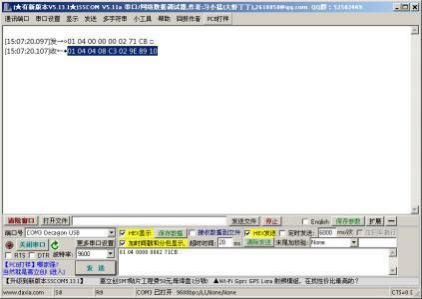
5.5 Use the serial port debugging software to communicate
Users can use any serial port debugging software to communicate with the sensor. Pay attention
when communicating, select the correct serial port, baud rate, and other serial port communication
parameters, and the data that needs to be sent and received must be transmitted anddisplayed in
hexadecimal .
第 13 页 共 14 页
©2008-2023 Seeed Technology Co., Ltd. All rights reserved. www.seeedstudio.coUser Manual
6. Maintenance
6.1 Use and Maintenance
Operation Recommended maintenance
Cleaning sensor probe Washit every 30 days
Check the sensor and fluorescent film
Check it every 30 days
heads for damage
Replace the fluorescent film head Replace it 1~2 years
Calibrating sensor 3~6 months
External surface ofthe sensor: Clean the external surface ofthe sensor with tap water. If debris
remains, wipe it with a damp soft cloth. For some stubborn dirt, you can add some household
detergent to the tap water to clean it.
Check the cable ofthe sensor: the cable should not be tight during normal operation, otherwise it
is easy to break the wire inside the cable and the sensor cannot work normally.
Check whether the measurement window ofthe sensor is dirty and whether the cleaning brush is
normal.
Sensors contain sensitive optics and electronics. Make sure the sensor is not subject to severe
mechanical impact. There are no user-maintainable parts inside the sensor.
6 .2 Calibration
a)Zero calibration
Use a larger beaker to measure an appropriate amount ofzero dissolved oxygen liquid, place the
sensor vertically in the solution, the sensor measuring end is at least 10cm away from the bottom of
the beaker, wait for 3 to 5 minutes for the value to stabilize and perform zero calibration.
b) Slope Calibration
Place the measuring end ofthe sensor in the standard solution, the measuring end ofthe sensor
should be at least 10cm away from the bottom ofthe beaker, wait for 3 to 5 minutes for the value
to stabilize, and perform slope calibration.
第 14 页 共 14 页
©2008-2023 Seeed Technology Co., Ltd. All rights reserved. www.seeedstudio.coYou can also read