ENGLISH - Yamaha Motor Co., Ltd.
←
→
Page content transcription
If your browser does not render page correctly, please read the page content below
ENGLISH

                                                                                        Robotics Operations, FA Section
                                                                                        127 Toyooka, Kita-ku, Hamamatsu, Shizuoka, Japan, 433-8103
                                                                                        Tel: +81-53-525-8350 Fax: +81-53-525-8378
                                                                                        Web: https://global.yamaha-motor.com/business/robot/
Product specifications and appearances may be subject to change without prior notice.   Email: robotn@yamaha-motor.co.jp

202010-JE
YAMAHA ROBOT
R obonity
Motorless Single-Axis Actuator
Series
Who we are and what we do
See p. 20 for a quick selection table
Over four decades of proven reliability
At Yamaha, development in the
field of robotics began with the Motor-less
implementation of robotic technolo-
gies on our motorcycle production
line over forty years ago. Basic model
Since then, our industrial robot
technologies have served as a
backbone for manufacturing equip- LBAS High rigidity
This model offers about three times the rigidity
High precision
Straightness (running parallelism): +/-0.02/800 mm
ment in a wide variety of industries, including in the assembly of
seen in our existing models. NEW NEW
electronic products, the transport of in-vehicle components, and
LBAS features a new, integrated guide rail
the manufacture of large LCD panels. MY
Existing product
LBAS05
Existing product
LBAS08
Over the years, we at Yamaha have done our utmost to always and frame structure and a compact frame MY
T6L
35 59 MY
T9H
86 221
continue improving upon what we've put to market. Those efforts MP 63 MP 309
size with improved load capacity that is
40 133
serve as a testament to our reliability when it comes to producing MR MR 50 103 MR 117 343
MP
(N . m) (N . m)
what businesses need.
designed to accommodate motors produced
A legacy of unique technologies and a by most of the major manufacturers. Right angle attachment kit allows for motor Compact
keen sense for market orientation changes The frame width is about 20% smaller when compared to
our existing model.
Straight Mount Right Angle Mounts
Motor Control Technology is absolutely NEW
necessary for precise, high speed
operation. Controller Development
High rigidity Existing product
T6L
LBAS05
Technology is based on the highest
standards of evaluation. And Signal Compact Standard Left Right Bottom 65 54
Processing Technology allows for
Installation is simple Maintenance is easy
stable operation even under extreme
environmental conditions. Our products are characterized by high-
Low cost Mounting holes are accessible from both above and below. No disassembly of actuator units is Moving parts can be lubricated from the outside with no opening
ly-praised rigidity, durability and operability, and our Core Technolo- required. The side features a standard surface and dowel pin holes are found on the bottom. of the actuator required.
gies* allow us to provide just what the market needs. Maximum payload 2 kg to 100 kg
*Core Technologies refers to control boards, linear motors, linear scales (position detectors)
and other such technologies.
Maximum speed 133 to 1,333 mm/sec 54
Stroke 50 to 1,100 mm
Testing environments that Standard
surface 26.7+/-0.03 27
guarantee greater reliability A grease nipple is found on the side of the slider
At Yamaha, we continue evaluating Advanced model
our technologies to ensure that our
LGXS
products are reliable. During prod-
uct development, we conduct Shortest overall length Ready for cleanroom use
assessments and tests in our own
anechoic chambers* to ensure the We have achieved the Features a protective stainless steel dust shield along with
kind of reliability and quality that LGXS features ground ball screws to ensure shortest class in the industry ports that are ready for vacuum fittings.
businesses count on. when it comes to total Simply attach the vacuum fitting
*Our anechoic chambers have been set up to help us in the overall development of EMC greater efficiency, accuracy and reliability, length in relation to
Stainless steel dust shield
(Electro-Magnetic Compatibility) technologies deployed in products produced by Yamaha the effective
Group companies. This allows us to ensure compliance with international regulations and
conformity with international standards.
making this product ideal for use as a the stroke. Cleanroom roller mechanism
base axis in a multi-axis setup.
Yamaha quality means safety Vacuum ports
We have a system in place which High precision (accuracy class of C5)
integrates the areas of manufactur-
ing, sales and technology into one High precision Optional conversion unit allows for motor
well-oiled machine. We leverage High Durability Features ground ball screws, a lead precision accuracy class orientation changes
this system to the utmost to of C5, and a repeated positioning accuracy of +/-5 µm.
produce consistency when it comes Motor units of a standard, straight type can
to inspection, manufacturing, Cleanroom compatibility comes standard be used for side-mount setups.
assembly, inspection and shipping
processes. This allows us to provide high levels of quality, afford-
LM guide
able prices, and quick deliveries. Maximum payload 2 kg to 160 kg
Processing and machining for key components is all done in Ball retainers
Maximum speed 300 to 2,400 mm/sec
house. As a robot manufacturer, we provide the kind of quality Ground ball screws
that you will find nowhere else. And when it comes to quality Stroke 50 to 1,450 mm
JIS C5 accuracy
control, our customers can expect only high-quality craftsmanship
achieved by rigid adherence to strict standards. Standard Conversion adapter Attachment with bend to the right
02 YAMAHA ROBOT LINEUP YAMAHA ROBOT LINEUP 03
T R ANSERVO
CLOSED LOOP STEPPER MOTOR SINGLE-AXIS ROBOTS
Series
See p. 21 for a quick selection table
The TRANSERVO series brings to you compact and economical single-axis The position detector is a resolver
The resolver used features a simple yet sturdy structure employing no electronic components
robots which feature a fusion of the low cost of a stepper motor and the or optical elements. This makes it extremely tough and great for use in harsh environments.
Breakdown rates are also kept low and the structure of the resolver experiences none of the
detection-related problems seen in other detectors, such as optical encoders that experience
functionality of a servo motor. breakdowns of electronic components or which see moisture or oil sticking to the disk.
SS Slide type SG Slide type SR Rod type
type type type
Inline model Foldback model Standard model Model with support guide Foldback model
(Slide type)
SG07 SR05 SR04 SRD05 SRD04 SR04-R SRD04-U
SS05H-S SS05-S SS05H-R(L) SS05-R(L)
STH Slide table type RF Rotary type BD Belt type
type type type
Inline model Foldback model Standard model High rigidity Inline model
model
RF02 BD04
STH04-S STH04-R(L) RF03 BD05
STH06-S STH06-R(L) RF04 BD07
Features and benefits of the STH type (slide table type)
Closed-loop control for position feedback Features and benefits of the SS type (slide type) Features and benefits of the SR type (rod type) Circulation type linear guide for high rigidity and
High-speed operation means lower production time Maintenance required less frequently accuracy
While stepping motors can be deployed at a low cost, they experience drastic
drops in torque at high speeds and offer no hunting oscillation (micro vibra- TRANSERVO leverages the vector control method to the greatest extent possible
A lubricator used in the ball screw along with a contact scraper provide the prod- This product features a maximum pressing force of 180 N and a repeated positioning
tions). to maintain a constant payload even under high speed conditions. This means a accuracy of +/-0.5 mm. Integrating a guide rail and slider ensures less bending and the
uct with a long service life extended periods where maintenance is not required.
Our TRANSERVO series eliminates these problems with the deployment of drastic reduction in cycle time. This combined with the high-load ball screws circulation type linear guide provides high rigidity and accuracy. The allowable
an innovative vector control method, which means that the series delivers the means that the TRANSERVO series provides a maximum speed of one meter per No maintenance needed for long periods of time overhand provided by STH06 exceeds that seen in the T9 model of the FLIP-X series.
same functionality of a servo motor with the lower cost of a stopping motor. second,* which is as fast as single-axis servo motors found in the same category. Grease-saving lubrication system The STH type is optimal for precise assembly.
Prevents particle contamination
*SS05/SS05H/SSC05/SSC05H (lead: 20 mm)
Dowel pin for positioning
Simple design High-pitched operating noise
Stepping & low cost High-speed operation means lower production time
Drop in torque at high speeds Ball screw lubricator
No vibration Payload is
Motors Heavy power consumption
always
when stopped when stopped Lubricators keep grease within a
constant!
high-density fiber net to supply just
TRANSERVO the right amount. Nothing is wasted.
Payload
Smooth movement
Servo Micro vibrations occur
Highly reliable resolver used Body installation
Constant torque
through-hole
Motors at all speeds when stopped
Resolvers used as position
Saves energy High cost Ordinary type
sensors are both rugged and
Only small payloads sturdy. All models can be equipped Integrated guide rail
can be deployed
with a brake. Workpiece installation tap and slider
at high speeds...
TRANSERVO brings together the best of both worlds
Layered contact scraper
RFeatures and benefits of RF type (rotary type)
0 200 400 600 800
Features and benefits of the SG type (slider type) Speed (mm/s) A dual layer scraper prevents micro-contaminants on the rod
Dynamic payload—46 kg horizontally from getting inside and also effectively curbs looseness or The first rotation axis model in the TRANSERVO series
vibration in the rod.
and 20 kg vertically Longer service life thanks to two-point contact Featuring a maximum speed of 420 degrees per second and a repeated positioning
guides featuring four rows of circular grooves accuracy of +/-0.05 degrees, the RF type is a thin, electric rotary type actuator. There
Payload capacities are
increased a great deal thanks
SS05H SG07 Features and benefits of the BD type (belt type) are two models which can be selected in accordance with the application: the standard
Guides maintain the rolling movement required with minimal differential ball slippage, type and a high-rigidity type. The RF type is very easy to use and allows for simple
to the deployment of a rigid Maximum payload Maximum payload
even when a large-momentum load is applied or when accuracy (flatness) on the For long stroke applications installation of the workpiece on the table and on the base frame. The RF type can be
table slide and a 56 motor. The Four-fold
result is a maximum payload of increase installation surface is sub-par. This rugged design means that breakdowns resulting used for rotational transport taking place after chucking and for vertical rotation when
This product ensures high speed operation with
46 kg, with the limit being 20 from abnormal wear and other such phenomena seldom occur. combined with a gripper.
kg when it comes to transport 12 kg 46 kg its long maximum stroke of 2000 mm and a
using vertical specifications. maximum transport speed of 1500 mm/sec. High-rigidity bearings mean
No exterior parts (such as the cover) need to less displacement in radial
be removed when installing. A shutter is also and thrust directions of the
provided as a standard accessory, which table
Maximum speed of 1200 mm/sec
Maximum
speed is 1.2
times more
current model Maximum speed
than the
current
securely covers the guide and belt to prevent
The maximum speed provided is 1.2 times SS05H 1000 mm/sec model
grease from scattering about and serves to
faster than that offered by the current model Maximum speed
prevent contamination by foreign objects. This The shutter comes as
SS05H, making it possible for your equipment SG07 a standard accessory
1200 mm/sec product is best suited for workpiece positioning and protects internal
to reduce cycle time. or transport taking place over long distances. mechanisms High rigidity model
04 YAMAHA ROBOT LINEUP YAMAHA ROBOT LINEUP 05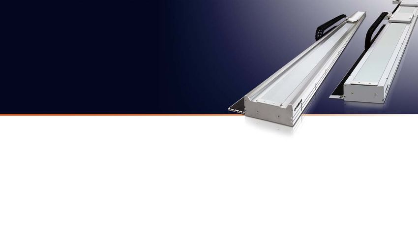
FL I P - X
SINGLE-AXIS ROBOTS
Series
PHASER
LINEAR MOTOR
Series
SINGLE-AXIS ROBOTS
See p. 22 for a quick selection table See p. 23 for a quick selection table
Our single-axis robot series includes 6 types and 29 variations, meaning No critical speed restrictions required up to long strokes of 4 meters
a broad range of options are available Excellent performance during long-distance transport
T Compact model N Nut rotation model F GF High rigidity model MF Long stroke and high power using a flat motor with a core
type type type type type
T4L/T4LH, T5L/T5LH, T6L, T9/T9H N15/N15D, N18/N18D F8/F8L/F8LH, F10/F10H, F14/F14H, Double carrier comes standard
F17/F17L, F20/F20N, GF14XL/GF17XL
Maximum stroke: 4050 mm
Maximum speed: 2500 mm/s
Repeated positioning
accuracy: +/- 5 µm
Maximum payload:
7kg to 160 kg MF7 MF7D MF15 MF15D MF20/20D MF30/30D MF75/75D
This model provides a compact body at an affordable price and is This model allows for operation even under long stroke The model features a highly rigid aluminum frame, which provides
ideal for installation director on a mount. conditions, all while maintaining maximum speed and remaining high levels of load moment and offers strength against offset loads.
unaffected by critical speed. Double carrier specifications also The model is suitable for use in Cartesian robots requiring arm
come standard. rigidity and for moving arms which move the overall axis. Yamaha in-house components means lower costs
Magnetic scales originally developed by Yamaha are still being produced by us
MF7 (Linear motor) F17 (Ball screws) B10 (Belt type)
B Timing belt drive model R Rotary axis model today. We also manufacture other major components to ensure significant
type type Stroke Stroke Stroke
B10, B14/B14H R5, R10, R20 reductions in cost. Linear mechanisms are no longer something special as we
With a maximum stroke length of 3050 mm, this model allows for long-distance transport between job processes. This model provided a repeated positioning accuracy of are now in an era where they they can stand shoulder to shoulder with ball Accuracy Accuracy Accuracy
+/-30 seconds (meaning 0.0083 degrees). The R type can screws as the right tool for the job. Speed Speed Speed
be combined with other robots for use as the rotation axis
or for a broad range of other applications, like index tables. The linear motor type will particularly provide lower costs when it comes to
The product's harmonic driver provides great strength and transporting lightweight workpieces over long distances at high speeds.
accuracy.
Size Maintenance Size Maintenance Size Maintenance
Comparison of single-axis robot models
A resolver built for harsh Two-point contact guides featuring four Model Unit cost*1 Maximum speed Payload Repeated position accuracy Maximum stroke Frame dimension*2 (W × H)
(µm) (mm) (mm)
(mm/sec) (kg)
environments rows of circular grooves help in dealing
MF7-1500 2500 10 (7)*3 +/-5 4000 85 × 80
A highly reliable resolver is used for the detection of motor positions, which with large moment loads
ensures the steady detection of positions even under harsh conditions where F17-40-145 720*4 40 +/-10 1450 168 × 100
Two-point contact guides featuring four rows of circular grooves allow for less
powder particles or oil mist is found. When it comes to resolution performance, differential slip. Differential slip experienced by the ball is low when compared B10-1450 1850 10 +/-40 2550 100 × 81
the resolver provides an amazing 20480 pulses per revolution. to four-point contact guides with two rows of Gothic arch grooves. This means
1. Comparisons using the strokes noted above. 2. Cable carrier not included. 3. Becomes 7 kg when the maximum speed is 2500 mm/s (meaning 2100 mm/s when transferring 10kg).
that excellent rolling motions are provided even when dealing with large 4. Value determined in consideration of critical speed when the stroke is 1,450 mm.
moment loads or poor installation surface accuracy. Malfunctions, such as that
resulting from unusual wear, are also much less frequent. 3.0
High speed, long travel
Speed (m/s)
Movement at
Optical encoder Resolver Conventional Yamaha a fixed speed of 2.5 m/sec
2000 st per 50 kg
2.5
PHASER (MF75)
Four-point contact guides with Two-point contact guides featuring The ultimate appeal of linear motor single-axis robots is that there are critical speed limits like you would see when PHASER
FLIP-X (F20N)
2.0
two rows of Gothic arch grooves four rows of circular grooves dealing with ball screws. Even long-distance travel means no reduction in maximum speeds. Standard maximum Movement at
stroke goes up to 1050 mm with the MR type and up to 4000 mm with the MF type. Cycles times for long-distance 1.5
a fixed speed of 1.2 m/sec
transport have particularly seen drastic improvements. 1.0 FLIP-X
0.5
0
0 0.5 1.0 1.5 2.0 2.5
Optical Magnetic type Time (sec)
Complicated structure with electronic A simple structure comprised of Movement profile of linear single-axis PHASER
parts required an iron core and winding means and single-axis robot FLIP-X
Trouble with electronic parts,
condescension of dew and the sticking
less potential for failure
Highly impact resistant and resilient
Large differential slip Small differential slip and Standard double carrier setup saves
and resistance to friction good self-centering
of oil on the disc occur more frequently against electronic noise
Highly impacted by poor installation Highly resistant to alignment
spaces and ensures great efficiency
precision, friction and elastic fluctuations and moment loads This product allows you to lower the costs involved and decrease
Risk of detection failure High reliability deformation
May break down even during the
Seldom breaks spaced used in comparison to the usage of two single-axis robots.
No axis alignment is needed and tools can be shared, which shortens
calculated service life
setup time. Lastly, an anti-collision control function is provided when
making use of the RCX series controller.
Customization for each model available A long service life means you save on mainte-
If you are looking to do special orders for any of our models (double sliders, nance and management Ball screw type single-axis Space-saving double
wide sliders, etc.), please inquire with a sales representative. Our highly rigid ball screws and robots (2 units) carriage
guides are a huge help in letting you
save on maintenance and manage-
ment costs. Visit our website to find Maximum payload capacity of the MF series: 160 kg Lower noise levels and longer service lives
out what you can expect in terms of
Flat magnets are deployed within the MF series, meaning that heavy When compared with ball screw type robots, there are fewer sliding and rotating
the service life of a given product
under certain conditions. objects can be transported at high speeds with a high level of accuracy. sections, meaning that operation is exceedingly quiet. Coils and magnets do not
make contact, meaning no wear is experienced, making the the robot usable for
extended periods of time.
06 YAMAHA ROBOT LINEUP YAMAHA ROBOT LINEUP 07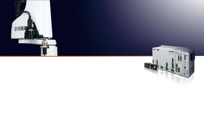
X Y-X Series M U LT I - F L I P /
CARTESIAN ROBOTS M U LT I - P H A S E R
See p. 23 for a quick selection table MULTI-AXIS ROBOT
Custom orders
From compact, economical and light-duty systems to large, Custom multi-axis systems are also
available. Please inquire with a Yamaha
One controller for multiple single-axis robots
heavy-duty systems, a variety of pre-configured multi-axis representative near you.
systems are available Advantages of multi-axis controller operation Robot setup
Sequence control is simple and system upgrades are inexpensive 2-unit robot configuration
More compact and saves more space than situations where multiple A multi-task program used with this configuration allows for asynchronous,
Arm type Gantry type Moving arm type independent operation.
single-axis controllers are being operated
Allows for a greater level of control Using this alongside an auxiliary axis configuration means even more
freedom when it comes to assigning an axis to a task.
RC320 and RCX340 (multi-axis controllers) provided mixed control
involving the PHASER series (linear single-axis) and FLIP-X series Synchronized double configuration
This configuration allows for the addition of two motors
to one axis on types of robots where motor units run
1st axis / MF15 separately, such as the linear motor single-axis
PHASER series or the N type (nut rotation type) FLIP X series.
Main auxiliary axis configuration
2nd axis / F14
XZ type Pole type Dual-synchronous drive Use this auxiliary axis configuration when it's impossible
to have simultaneous movement take place using the
The dual-synchronous MOVE command. Axes configured as main auxiliary
drive has two axes being 3rd axis / C14
controlled in synchroniza- axes move only with the DRIVE command (meaning
tion with one another. This a separate movement command issued to a
means that they are particular axis) and cannot be operate via the
effective for the carrying of
heavy items and for long Example of 4th axis / R5 MOVE command. That means this configuration is recommended for operation
stroke operation with a a 4-axis controller on an axis not synchronized with the main robot.
Cartesian robot.
Note: Custom orders are required for
dual drive functionality.
Synchronized dual configuration
Set things up like this when conducting dual-drive operation (meaning
simultaneous control of two axes). Use this dual-drive configuration on
gantry-type Catesian robots characterized by a long Y-axis stroke when going
Variations about stabilization during high levels of acceleration or deceleration, or in
situations involving heavy loads and high levels of thrust.
PXYx FXYx FXYBx SXYx MXYx
Y P-X
For specifications involving 3 or more
axes, please select from the following:
Series
Z-axis clamped base and moving
table type
Z-axis clamped table and moving
base type
SXYBx NXY NXY-W HXYx HXYLx
Resolver provides durability and Two-point contact guides featuring PICK & PLACE ROBOTS See p. 23 for a quick selection table
reliable position detection four rows of circular grooves
The position detector is a resolver featuring a simple yet robust structure Two-point contact guides featuring four rows of circular grooves allow for
which uses no electronic components or optical elements, making it less differential slip. Differential slip experienced by the ball is low when
extremely tough for usage in harsh conditions. It also seldom breaks down.
The structure of the resolver presents non of the detection issues seen in
compared to four-point contact guides with two rows of Gothic arch
grooves. This means that excellent rolling motions are provided even when Ideal for picking and placing small parts at high speeds
other detectors, such as optical encoders with electronic components
which experience breakdown or have moisture and oil sticking to the disc.
dealing with large moment loads or poor installation surface accuracy.
Malfunctions, such as that resulting from unusual wear, are also much less
Positioning via servo control means no mechanical adjustments required
The mechanical specifications when it comes absolute specifications and
incremental specifications are shared by all controllers, meaning that you frequent.
can switch to either absolute or incremental specifications with the mere
setting of parameters. 2-axis type 3-axis type 2-axis type
Even if the absolute battery gets completely worn down, the XY-X can Four-point contact guides with Two-point contact guides featuring
two rows of Gothic arch grooves four rows of circular grooves YP220BX YP220BXR YP340X
operate based on incremental specifications, meaning that the production YP320X YP320XR
lines never need to be halted if trouble occurs. Backup circuits have been YP330X
completely overhauled as well, meaning a backup period of one year.
Save money
Cutting down on the number of parts while boosting performance has
allowed us to lower our prices. The inclusion of a resolver within the struc-
ture means that that we have eliminated the idea that absolute units have
to be expensive. What's more, mechanical components remain unchanged
regardless of whether incremental unit specifications or absolute unit spec-
Large differential slip Small differential slip and High speed 0.45 seconds
per stroke
High precision Compact size
and resistance to friction good self-centering Ultra high-speed picking and placing The YP320X, YP320XR, YP330X The YP220BX unit has a compact
ifications are being used.
Highly impacted by poor installation Highly resistant to alignment means greater productivity. The and the YP340X provide both excel- size with an overall length of 109
Maintenance is easy precision, friction and elastic
deformation
fluctuations and moment loads YP22BX, when used under operating
conditions involving 50 mm in the verti-
lent high-speed performance and
high repeated positioning accuracy
mm. The moving arm mechanism
allows for the building of a compact
50mm
Though a built-in structure is employed, maintenance is made simple May break down even during the Seldom breaks
cal direction, 50 mm in the longitudinal (+/-0.02 mm). production line that interferes less
thanks to the ability to replace components like motors and ball screws on calculated service life
direction, 50 in terms of arch volume 150mm with its surroundings.
an individual basis. and a 1 kg load, provides a total cycle
time of 0.45 seconds.
08 YAMAHA ROBOT LINEUP YAMAHA ROBOT LINEUP 09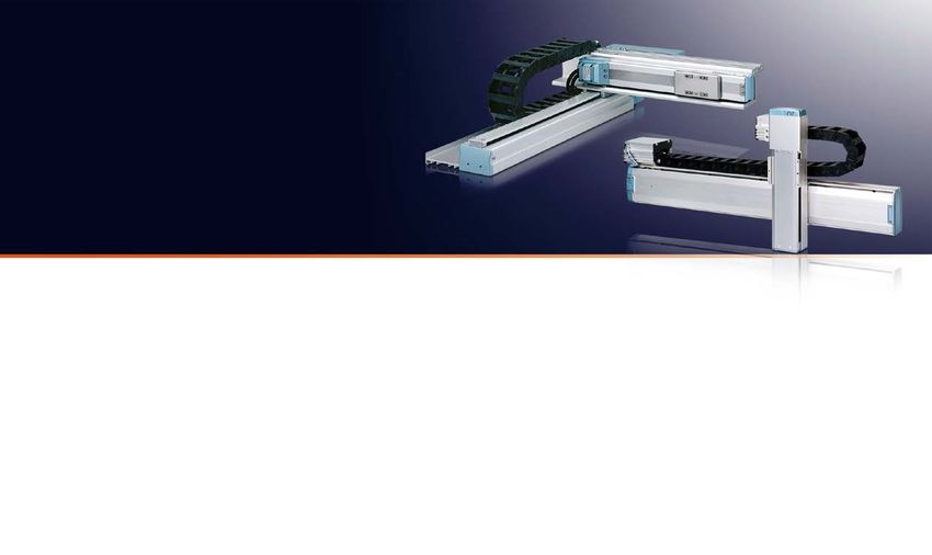
Y K-X
SCARA ROBOTS
Series
YK-XG
YK-XE
Direct drive beltless model
Low cost high performance model
Completely beltless structure
A ZR-axis direct coupling structure allows for a totally beltless structure. This
direct drive structure means a dramatic reduction in wasted motion. It also serves
to maintain high levels of accuracy over long periods of time and ensure mainte-
nance-free usage over extended periods of time, meaning there is no need to
worry about breakage, stretching or deterioration of the belt with age. This feature
applies to all XG series models and to YK180X/YK22X.
High speed
While standard cycle times are
no doubt fast, our designs also
put a focus on cycle times in
the regions where usage is
taking place. Drastic improve-
ments in maximum speeds
XY axis
Z axis
R axis
4.9 m/s
1.7 m/s
7.6 m/s
2.3 m/s
876 degrees/sec
1700
Increase of
45%
Increase of
35%
Increase of
were achieved through chang- degrees/sec 90%
YK-XGS Wall mount/inverse model Conventional model YK-XG series es made to gear ratios and Existing models
maximum motor RPM, result- YK500XG
See p. 24 for a quick selection table YK-XGP Dust-proof & drip-proof model Vertical shaft motor
ing in better cycle times during
Rotary long-distance movement.
shaft moto Vertical shaft
ball screw
An outstanding, diverse lineup featuring Rotary shaft Hollow shaft and tool flange options
hollow motor available
arm lengths ranging from 120 to 1200 mm. Useful additions include a hollow shaft to facilitate easy wiring leading to the tip
Delivers high-speed and high-precision of the tool and a tool flange used for clamping tools.
Note: YK250XG/YK350XG/YK400XG/YK500XGL/YK600XGL/YK610XE-10/YK710XE-10
operations for increased productivity.
Vertical shaft motor
(directly connected)
Extra small type SCARA model Low cost high performance model
Drive by pulley and
Rotary shaft hollow
YK120XG, YK150XG This model provides the only completely beltless structure timing belt
YK400XE-4 speed reducer
YK180XG, YK180X found in this class and you can look forward to high levels
YK510XE-10
YK220X of rigidity and accuracy even with the extra small type.
YK610XE-10
Maxim speeds have also been improved dramatically when
Arm length: 120 mm to 220 mm compared to the previous model, which was achieved by
YK710XE-10
Environmentally rugged resolver used
Maximum payload: 1 kg increasing the maximum RPM of the motor.
Increase of for position detection
83% A hollow shaft makes for easy touring of air A tool flange makes it easy to mount a tool to
1.8 m/s The position detector is a resolver featuring a simple yet robust structure which uses
X Yaxis tubes and harness wires the tip
3.3 m/s no electronic components or elements, making it extremely tough for usage in harsh
Increase of
conditions. It also seldom breaks down. The structure of the resolver presents non of
Z axis
0.7
29% the detection issues seen in other detectors, such as optical encoders with electronic Improved maintenance features
0.9 components which experience breakdown or have moisture and oil sticking to the Covers used in the Yamaha SCARA robot YK-XG series can be removed from
Arm length: 400 mm to 710 mm disc. The mechanical specifications when it comes absolute specifications and incre-
Maximum payload: 4 kg to 10 kg the front or in an upwards motion. Maintenance is easy since covers are com-
Existing model (YK120X) mental specifications are shared by all controllers, meaning that you can switch to pletely unattached to the cable.
YK120XG either absolute or incremental specifications with the mere setting of parameters. When it comes to replacing grease on a harmonic gear, ordinary robots require
Even if the absolute battery gets completely worn down, the SCARA can operate a great deal of time and effort since gears must be disassembled and because
based on incremental specifications, meaning that the production lines never need position deviations may occur. Yamaha SCARA robots, however, feature
Small type Medium type Large type to be halted if trouble occurs. Backup circuits have been completely overhauled as grease-sealed harmonic gears, meaning that no grease replacement is
YK250XG YK500XGL / XG YK700XGL well, meaning a backup period of one year. required (YK500XG to YK1000XG).
YK350XG YK600XGL / XG/XGH YK700XG Note: The resolver is comprised of a simple structure which forgoes the usage of any electronic components. It
YK400XG YK800XG is highly resistant to both high and low temperatures, impacts, electronic noise, dust particles, oil and other
YK900XG elements. The resolver is used in automobiles, trains and airplanes.
YK1000XG Affordable, superior performance YK-XE
YK1200X
Opt ical encod er Resolver The model provides improved efficiency and reliability when deployed
in production at an affordable price.
Arm length: 700 mm to 1,200 mm
Arm length: 250 mm to 400 mm Arm length: 500 mm to 600 mm
Maximum payload: 10 kg to 20 kg
Maximum payload: 5 kg Maximum payload: 5 kg to 20 kg
Note: YK700XGL is available for custom orders. Features of the wall mount/inverse type YK-XGS
Please inquire with a Yamaha representative for more details.
A completely beltless structures ensures high rigidity
Wall mount/inverse type Dust-proof & drip-proof model Optical Magnetic type
YK300XGS, YK400XGS YK250XGP, YK350XGP
Complicated structure with electronic A simple structure comprised of an iron Flexibility in terms of system designed improved as a result of having the
YK500XGS, YK600XGS YK400XGP, YK500XGP parts required core and winding means less potential conventional ceiling mount type model changed to a wall mount type. This
YK700XGS, YK800XGS YK500XGLP, YK600XGP Trouble with electronic parts, for failure makes possible the downsizing of production equipment. With the addition of
YK900XGS, YK600XGLP, YK700XGP condescension of dew and the sticking Highly impact resistant and resilient against
YK1000XGS YK800XGP, YK900XGP the inverse type to the lineup (which allows for upward operation), flexibility
of oil on the disc occur more frequently electronic noise
YK1000XGP, was also increased in terms of work directions. What's more, a completely
Arm length: 300 mm to 1,000 mm beltless structure means that there is a maximum payload of 20 kg and an
Maximum payload: 20 kg Arm length: 250 mm to 1,000 mm
Maximum payload: 20 kg Risk of detection failure High reliability allowable inertia moment of the R axis of 1 kgm2*. This is the highest level
available in the same class. Large hands can also be installed, making this
robot suitable for work entailing heavy loads.
Wall-mount type
This type is used when the
Inverse type
This type is used in cases
Superior rotary axis inertia moment capacity *YK700XGS to YK1000XGS
This model is designed for work environments involving frequent water splashing and dust
robot body is installed on a wall. where the wall-mount type (with the protection class being equivalent to IP65). SCARA robot performance is demonstrable by the standard cycle time alone. The
is mounted upside down. If you need protection from moisture generated by anything other than water, please contact us.
Note: YK700GP/YK800XGP/YK1000XGP are custom order models.
robot allows for a diverse range of heavy workpieces to be dealt with as well as Dust-proof and drip-proof type YK-XGP
large offsets. Having a low axis inertia moment when it comes to the R axis helps
Please inquire with a Yamaha representative for more details.
drastically in reducing cycle times. All SCARA robots produced we produce come
Bellows provide improved dust/drip-proofing
with speed reducers directly attached to the tip of the rotating axis, meaning the R Previous robot models were completely over-
Internal structure designed for optimal operation axis produces an extremely high allowable inertia moment which provides higher
speeds in terms of operation when compared to structures where positioning is
hauled to create a model type* that is dust
40 years of history Note: The example shown is YK500XG Structure with a directly-connected ball proof, drip proof and features an entirely
screw inherited from the single-axis robot
usually dealt with by a belt after deceleration takes place.
beltless structure deployable in working envi-
SCARA was our first robot. Since Independent spline shaft Built-in user wiring ronments were water droplets or dust particles
producing our first SCARA robot featuring high rigidity
Built-in user tubing YK120XG are found scattering about.
called CAME, we have spent some (Allowable moment inertia of the R axis: 0.1 kgfcms2)
This model type eliminates the issue of belt
forty years bringing SCARA robot If the weight load at the tip is 1 kg, operation deterioration and is perfect for usage in harsh
innovations to market. SCARA will be possible with an offset of about 100 mm.
approximate offset of 100 mm
environments. The use of an up/down
robots have undergone countless Specially-developed
hollow motor bellows-based structure also allows for
modifications in an ever-changing Allowable inertia moment of the R axis improvements in terms of dust proofing and
marketplace. The extensive track Comparison of YK120XG and a competitor's model
record we have built with SCARA drip proofing capabilities.
Figures when using a 1 kg load
Operation OK
robots have made them an essen- 1979 Operation deviates from allowable range of catalog values *YK250XGP to YK600XGLP
Operation
tial part of the Yamaha robot lineup. Offset Inertia
(mm) (kgfcms 2)
Equivalent to a protection grade of
YK120XG Company A
IP65 (IEC60529)
0 0.0039 Dust-proof and drip-proof connector for user
The harmonic gear used 45 0.025 wiring comes standard
for the rotary axis ensure 97 0.1
high levels of rigidity
and accuracy Allowable inertia moment of the R axis YK120XG: 0.1 kgfcms2
Company A: 0.0039 0.1 kgfcms2
10 YAMAHA ROBOT LINEUP YAMAHA ROBOT LINEUP 11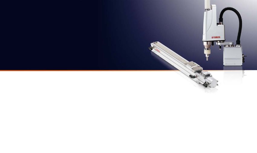
Y K-TW
ORBIT TYPE SCARA ROBOT
Series
YK 350T W
C LEAN ROOM Type
CLEAN ROBOTS
YK 50 0T W
See p. 24 for a quick selection table See p. 24-25 for a quick selection table
Equipped with high positioning accuracy and high speed. Defeats the Designed for the electronics, food, and medical industries,
limitations of other SCARA and parallel-link robots, leaving smaller and engineered for great suction and low particle emission.
equipment footprint and no dead space at the center of the work envelope. Delivers high cleanliness and excellent performance.
Covers bases within a 1,000-millimeter*2 reach Repeated positioning accuracy: +/-0.01 mm*1
The YK-TW series features SCARA robots with wide rotation angles and (XY axes)
a ceiling-mount configuration, with the YK500TW model capable of a
YK-TW robots boast higher repeated positioning accuracy than that of
YK-XGC/XC Clean room SCARA robots
reach of up to 1,000 mm under the arm. This greatly reduces footprint and type
parallel-link robots. This was achieved by striving optimal weight balance
lets them be free of movement restrictions during palletizing and Arm length: 180 mm to 1,000 mm
and re-designing the robots’ internal construction. Furthermore, the
conveyor belt assembly operations. Suction rate: 30 to 60 Nl/min
robots are equipped with highly rigid but lightweight robotic arms that are
fitted with finely tuned motors, allowing them to perform with high Cleanliness class: ISO 3 (ISO14644-1)
precision. Class 10 (FED-STD-209D)
C
Maximum payload: 20 kg
Y-motor
A B
Speed reducer
Orbit type SCARA robot
Movement
range R-motor
YK250XGC YK400XGC
Z-motor
C C
The Z-axis spline shaft is protected with bellows made of low dust emitting material and other sliding mechanisms are sealed completely. The entire harness assembly is incorporated inside the
housing, and dust emission is prevented by the air suction ports located on the back of the base housing.
A B
A B Vertical bellows improve cleanliness Fully beltless for higher
Standard type SCARA robot
reliability rigidity
Optimized gravitational
Hollow construction
moment for rotation FLIP-XC Single-axis clean room robots SSC Single-axis clean room robots (TRANSERVO)
Ideal for work in narrow spaces Coupled Y-axis motor and Obtained weight balance by type type
speed reducer unit with hollow placing R-motor and Z-motor on
Stroke: 50 mm to 2,050 mm Stroke: 50 mm to 800 mm
492 mm
Minimum construction enables wire the left and right.
installation harness to be inside of moving Suction rate: 15 to 90 Nl/min Suction rate: 15 to 80 Nl/min
width arm housing. Cleanliness class: Class 10* Cleanliness class: Class 10
Freedom of Maximum payload: 120 kg (horizontal installation) Maximum payload: 12 kg (horizontal installation)
Enabling 360-degree High speed, * C4L/C4LH, C5L/C5LH, and C6L conform to class ISO 3 (ISO14644-1).
movement rotation reduced inertia
492m Full use of workspace
m
underneath the unit
Lower profile, small footprint
The YK500TW is only 392 mm in height. Not only does it require little
space, it also gives greater freedom when adjusting its layout.
YK500TW YD11
C6L C5L C4L SSC04 SSC05 SSC05H
Perfect for enclosed The tip (R-axis) is able 392 mm Specifications of the FLIP-X series. Whether is it a lightweight, compact model, or one with a maximum Specifications of the TRANSERVO series. TRANSERVO robots use stepper motors and a newly
workstations and other to cross right under the payload of 120 kg, chose one that suits your needs from the 14 available. To achieve high cleanliness, developed vector control system to keep performance costs low and achieve functionality similar to
compact spaces main unit these robots have suction joints installed as standard features and use grease with low dust emission. servomotors’. To achieve high cleanliness, these robots have suction joints installed as standard
844 mm Their slide tables are also mounted with stainless steel sheets of excellent durability. features and use grease with low dust emission. Their slide tables are also mounted with stainless steel
sheets of excellent durability.
Standard cycle time down to 0.29 seconds*2
TK-TW robots are able to move with more flexibility in a horizontal plane. They are
built with a second arm (Y-axis) that moves under the first (X-axis). Due to their Easy to maintain
multiple-joint structure, TK-TW robots can move more efficiently from point-to-point.
Furthermore, with the weight balance of the internal components optimized, TK-TW
robots have their cycle time reduced by 36% as compared to previous models. XY-XC Clean room cartesian robots
Only 392 mm and 27 kg*2 type
Reduced Lower inertia, no bulky frame. Suction rate: 60 to 90 Nl/min
YK500TW Standard cycle time of Cleanliness class: Class 10
by
0.29 secs. Maximum payload: 20 kg
approx. 36%
Weighs only
YK500TW Approx. 74% lighter Maximum speed: 1000 mm/sec
Previous 27 kg
User wiring: D-Sub 25-pin connector (#1-#24 terminated, #25 grounded)
Yamaha User piping: Three 6-mm diameter air tubes
model YD11 75 kg
Cycle time
SXYxC
The standard cycle time for moving a 1-kg load 300 mm horizontally and
25 mm vertically has been reduced by approximately 36% compared to The YK-TW series comes with an optional installation frame. Cartesian robots for clean rooms. Using stainless steel sheets of high durability allows openings to be designed to the smallest possible, and the robots are capable of supporting Class 10
older Yamaha models. For more details, please contact a Yamaha sales representative. environments with minimal suction. Furthermore, with SCARA robots’ high-speed units used for SXYxC robots’ ZR-axis, cycle time is reduced significantly.
*1. Applies to the YK350TW *2. Applies to the YK500TW
12 YAMAHA ROBOT LINEUP YAMAHA ROBOT LINEUP 13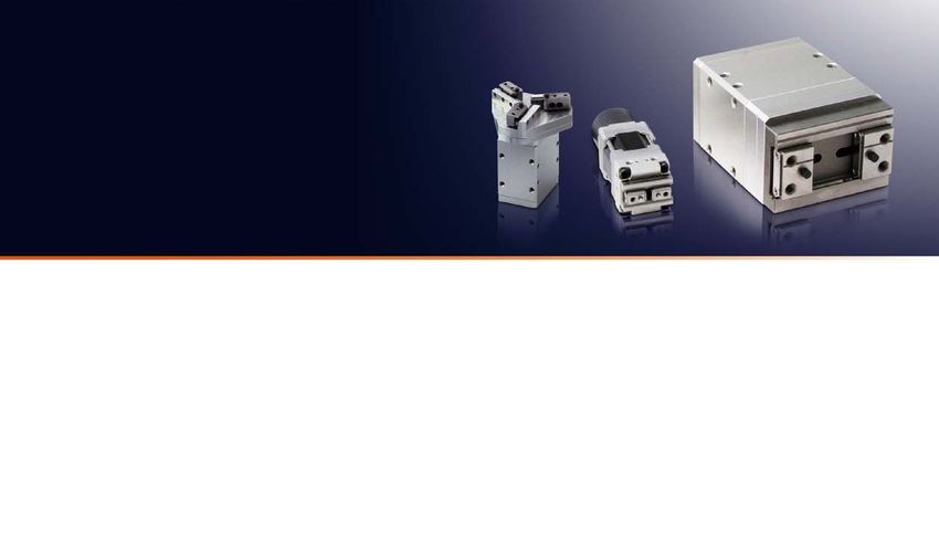
C ONTROLLERS R ROBOT VISION
CXiV Y2+ System
FOR THE RCX320/340
Choose what fits your needs from a wide range of control systems. Yamaha's own unique solution for integrated robot vision
Controllers come pre-programmed with servo parameters and Advanced RCXiVY2+ has been launched.
acceleration patterns so you can operate the robot straightaway.
RCXiVY2+ features: Robot controller integrated type
TRANSERVO FLIP-X PHASER P Robot positioners
■ Adjusting parts orientation on ■ Searching randomly placed part
RCXiVY2+ system
T4L/ T5L General
Stepper Small servos purpose servos Linear motors Simply specify a point the fly ■ Top/bottom judgement
number to operate PLC
motors (24V, 30W) (30–600W)
TS series robot positioners can be ■ Conveyor follower ■ OK/NG judgement
operated simply by assigning
point numbers and inputting the
start command. They can also
P P P perform point moves and push NEW
moves without the need for writing
I/O point trace
TS-X TS-S2 TS-SH
a program. Velocity can also be
changed during motion.
High speed positioning of irregular shaped parts
Remote command TS-P
(foods or clothes)
Blob search function
TS-S2 TS-SH TS-X TS-P D Robot drivers
Pulse train input drivers Suitable for pick & place or detection of parts with wide tolerance in shape and size, or
These drivers have done away high speed counting.
with operations that use robot
languages and use the pulse train Detection speed is 2 to 10 times faster that edge detection.
1 Simple calibration function is incorporated.
D D D input method instead. Their
2 Coordinates are corrected automatically
• Easy to use
• Various applications are
compact design allows them to be
1 axis
built easily into control consoles. even when the camera moves. supported using easy operation.
Pulse train 3 High-speed connections through • Cost reduction by reducing
dedicated bus line. work steps.
4 Controller is incorporated to provide • Robot and vision supported
the central operation. by Yamaha
TS-SD C RDV-X RDV-P 5 Applicable to all models of YAMAHA robot lineup.
RDV-X/RDV-P TS-SD
ERCD
Conveyor tracking
Program C Robot controllers
Also supports moving camera Camera position can be selected in
C C accordance with the application. Ideal for high-speed packaging arrangement high-speed transport
(Yamaha SRC language) Fixed camera Fixed downward. Fixed upward. of multiple types of items such as pharmaceuticals, cosmetics, and
1 axis Even if the camera is mounted on the robot,
I/O point trace coordinates are automatically converted according food products.The vision camera detects the position and orienta-
to the robot's movement. tion of parts moving on the conveyor, and the robot picks them up.
Remote command
Online command SR1-X SR1-P
CMOS camera
Palletizing robot
ERCD SR1-X SR1-P Movable camera SCARA robots Cartesian robots
2 axes 3 or 4 axes
Program C
(Yamaha BASIC language)
2 axes
RCX320
I/O point trace
C C
Remote command Even when the camera is moved, the
coordinates are corrected automatically.
Online command RCX221 RCX222 RCX320 RCX340
RCX222 RCX221 Supply conveyor Pallet Collection conveyor
Diverse command methods
Program
There are different methods to choose from: programs, point trace,
remote command, online command, and more. Programs use a
Setup time reduced greatly Example program
3, 4 axes
BASIC-like Yamaha language capable of executing various
(Yamaha BASIC language) operations, be it simple tasks, or I/O output and conditional When using third-party vision, a coordinate conversion program needs to be created in the New CTMOVE CTMOVE (1),Z=0.0,CTZ=10.0
branching. robot controller since the robot coordinate data differs from the vision format. Can be executed with a Unify the move up command, follow
I/O point trace In RCXiVY2+, vision system is incorporated in robot controller the robot coordinate data workpiece command, move down command
C single command
Remote command can be stored into the robot point data using single process. This ensures very simple
Comprehensive software
RCX340 Seamless movement from
operation. Additionally, the unified control of the camera control and light control can be move up to move down
Online command performed using the robot program. Start-up process will be greatly simplified.
The applications for the controllers are designed
to let users operate the robots, teach points, Predict workpiece
create and edit programs, and perform other tasks Comparison of setup time location and move
simply and easily on the screen. directly
80%
up to 16 axes
The master With YC-Link/E, Setup time reduced
controller controls the Master can Unprogrammed Installation Conveyor direction
be connected by up to
all programs and controllers Calibration Tracking
to the Slaves
settings. using LAN cables.
start position Workpiece pickup location
RCX-Studio 2020 RCXiVY2+ Setup time is shortened greatly Pattern registration
RCX340 is capable of PLC
(Programmable Logic Controller) system
Parameter setting
Reduce movement distance
Master Slave Slave Slave
controlling up to four Communication setting
Program setting Workpiece position when
robots (or 16 axes) RCX-Studio 2020*
tracking begins
TS-Manager VIP+ General-purpose
Debug
*Web download only. vision Setup time Operating conditions: YK500XG / payload 1 kg (total of workpiece and tool) / horizontal
movement 250 mm / vertical movement 1 mm / conveyor speed 100 mm/sec
14 YAMAHA ROBOT LINEUP YAMAHA ROBOT LINEUP 15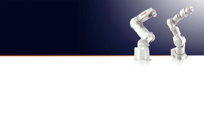
YRG
ELECTRIC GRIPPERS
Series
YA
VERTICALLY ARTICULATED ROBOTS
Series
6-axis 7-axis
See p. 26 for a quick selection table See p. 26 for a quick selection table
Easy operation enabled by Yamaha's robot language. Increase productivity Ideal for constructing compact cells, moving and
assembling small parts, or inspection processes.
Gripping force control Measuring Speed control Multi-point control Workpiece check function
Speed can be set in The HOLD signal determines
Can be set in increments of Measures a workpiece by increments of 1% in the range Up to 10,000 positioning if workpieces have been picked
1% in the range of 30 to 100% detecting its position of 30 to 100%, and the range
of 1 to 100% for acceleration
points possible up or dropped, even without
the use of a sensor
6-axis robots 7-axis robots
S type Single cam type W type Double cam type
Fast, compact, lightweight High gripping force
YA-RJ YA-R3F YA-R5F YA-R5LF YA-R6F YA-U5F YA-U10F YA-U20F
Arm
U-axis B-axis
YRG-2005SS YRG-2010S YRG-2815S YRG-4225S YRG-2005W YRG-2810W YRG-4220W
High-speed operation High wrist load
workpieces are
T-axis
Screw type 3-finger type reduces cycle time 6-axis robots
Thanks to high-speed, low-inertia AC servo also supported R-axis S-axis: Allows horizontal body rotation
Straight style “T” style Compact, high rigidity, long stroke motors, an arm designed to be lightweight, With a wrist section that has the L-axis: Allows forward/backward movement
High precision, long stroke and the latest control technology, these highest allowable moment of Body U-axis: Allows the arm to raise and lower
robots achieve an operating speed that is inertia in its class, these robots
best in their class. From supply, assembly, L-axis R-axis: Allows arm rotation
can support jobs involving a high
inspection, and packing to palletization, all wrist load, or simultaneous B-axis: Allows wrist of the arm to tilt up and down
applications can enjoy shorter cycle time handling of multiple workpieces. S-axis T-axis: Allows wrist of the arm to rotate
and improved productivity.
YRG-2020FS/YRG-2840FS YRG-2020FT/YRG-2840FT YRG-2004T YRG-2013T YRG-2820T YRG-4230T Dramatically reduce line setup Arm
B-axis
T-axis
time with a simulator
Free arm movement
Electric grippers for positioning, speed control, and high-precision gripping performance We provide software* that lets you use 3D CAD Interference check
program further boosts
U-axis
R-axis
data to construct a production facility in virtual
YRG grippers deliver what was challenging for the air-driven ones—gripping force control, speed and acceleration control, multi-point positioning, and space on a computer, and easily perform productivity.
the ability to measure workpieces, making them suitable for catering to a wide range of applications. engineering tasks such as creating programs
and checking for robot interference. Teaching 7-axis robots
Gripping force control Multi-point control Workpiece check function can be performed even before the actual
production line is completed, dramatically S-axis: Allows horizontal body rotation Body E-axis
YRG grippers’ gripping force can be set in 1% Gripper fingers can be configured to desired posi- The electric grippers output the HOLD signal, reducing line startup time. L-axis: Allows forward/backward movement
increments. They are capable of gripping glass, tions that correspond to workpiece sizes. This which checks for workpieces that were not gripped *Optional L-axis
spring, and other workpieces that are fragile or feature improves the efficiency of assembly lines, or dropped during transfer. No external sensor is E-axis: Allows the arm to twist
S-axis
easily deformed. The gripper force remains where changeovers are frequent and different needed. U-axis: Allows the arm to raise and lower
constant even with finger position changes. workpiece sizes and materials are found. 7-axis 7-axis
R-axis: Allows arm rotation
Pneumatic control Electric control Pneumatic control Electric control Pneumatic control Electric control Reduced space Able to reach B-axis: Allows wrist of the arm to tilt up and down
Difficult to make fine Gripping force can be set Results in stroke loss. High positioning Image processor or sensor Detects fallen allows sophisticated workpieces from T-axis: Allows wrist of the arm to rotate
adjustments to the
regulator.
in a range of 30% to
100% in 1% increments.
accuracy prevents stroke
loss.
detects workpieces that
were dropped or missed out.
workpieces without an
external sensor. system layouts around or under
Since these robots can be Rotation of the seventh axis enables flexible Controller Specifications YAC100
installed close to workpieces movements with the same freedom of move-
or other equipment, you can ment as a human arm, allowing the workpiece
reduce the space required for YAC100 Controller Specifications
to be accessed from around or from under. This Configuration Standard: IP20 (open structure), Option: IP54 (dustproof housing)
your production facility.
allows the robot to enter narrow locations that a Dimensions (H x W x D) 200 x 470 × 420 mm (excludes protrusions)
Achieves By locating multiple robots Mass 20 kg
improvements close to each other,processing person cannot fit in, or to approach the work- Cooling system Direct cooling
to takt time can be integrated and short- piece in a way that avoids obstructions, giving Ambient temperature During operation: 0°C to +40°C During storage: -10°C to +60°C
Relative humidity 90% max. (non-condensing)
ened. you more freedom to design the layout for
Single-phase 200/230 VAC (+10%, -15%), 50/60 Hz
Only a single controller Supports a variety of shorter cycle time and reduced space. Power supply*
Three-phase 200/220 VAC (+10%, -15%), 50/60 Hz
needed for control applications by being Robot vision system: iVY2 System Grounding Grounding resistance: 100 or less
7-axis Specialized signals: 10 inputs and 1 output
combined with vision system Digital l/Os General signals: 28 inputs and 28 outputs
"Elbow movement" unique to
Max. I/O (optional): 1,024 inputs and 1,024 outputs
The grippers require just a single controller. Setup With YRG grippers integrated into the robot Positioning system By serial encoder
and startup are significantly simpler as there is no vision system iVY2, RCX340 can be used to Camera Lighting
7-axis models allows optimal Programming capacity
JOB: 10,000 steps, 1,000 instructions
CIO ladder: 1,500 steps
need for communication with PLCs or other host
devices.
control the camera for positioning and work-
piece handling. An advanced system, but
posture to be maintained Expansion slots
LAN (connection to host)
MP2000 bus × 5 slots
1 (10BASE-T/100BASE-TX)
easily constructed. The 7-axis U-type robots allow "elbow move- Interface RS-232C: 1ch
Electric gripper: YRG series Elbow movement Control method Software servo control
ment," changing only the elbow angle without
*The RCX240 controller can be used too. with unchanged Six axes for robots, two more axes can be added as external axes
affecting the position or posture of the tool. This flange position
Drive units
(installable in the controller)
permits operation to avoid nearby obstructions. Paint color Munsell notation 5Y7/1 (reference value)
*YA-R6F: Three-phase only
16 YAMAHA ROBOT LINEUP YAMAHA ROBOT LINEUP 17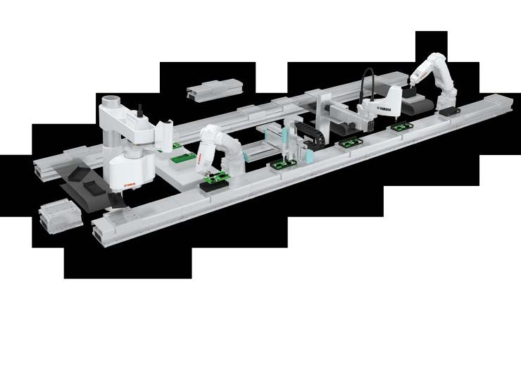
L C M R 20 0 / L C M10 0
LINEAR CONVEYOR MODULE
See p. 28-30 for a quick selection table
Capable of circulating /
Module structure cycling motion
Proposed by the pioneer of linear transport: Variable speed control between LCMR200 / LCM100
Revolutionary transport platform work stations. Narrow pitch movement
Direct drive Narrow pitch operation
for next generation manufacturing High-speed movement
Operation directly
on slider ● Servo controlled direct drive eliminates mechanical stoppers and position sensors.
Production line using LCMR200
Accurate Bi-directional move ● Simple position setting by entering point data in a program. Narrow pitch
stop movement
Smooth acceleration and deceleration ● Flexibility in setup for production lot change
Direct positioning ● Saving flow time by narrow pitch incremental move and high speed move.
Reduce Improve Cost reduction Save space.
transport time. productivity.
Process sharing Assembly can be done while parts are on conveyor
Direct drive Slider backward travel Highly rigid guide
● Carriage is bi-directional and one work station can perform more than one task. Saving total line cost and floor space. ● The highly rigid guide enables assembly and processing on the transport line.
● High speed bi-directional move and simultaneous independent operation of multiple carriages. ● No need to reposition parts to/from conveyor. Floor line space is reduced substantially.
Conventional method Requires two duplicated work stations in one line LCMR200 / LCM100 Eliminating duplicated work station Conventional method Parts need to be moved to work bench LCMR200 / LCM100 Assembly work is done while parts are on conveyor
Duplicated process
Process C
A B A C A
Retracting the work Process C
Can perform work on the slider
A A B Process B
Duplicated tasks A C Process B
Process A
A B
Process A
B C
A
C Bi-directional feature reduces total line cost = Equipment Equipment
assembly cost space space
Floor space reduced
Reduce transport time. Finished Finished Controller
Controller for LCMR200
Transfer Stop Work Transfer YHX controller
LCMR200 /
High-speed
movement
Direct positioning
Accurate
stop
Work on the slider is possible
High-speed
movement
Transfer time is reduced
from 6 to 3 seconds.
50%
reduction
LCM100 in tact time
● One YHX controller set can control the entire
Linear motor drive for Optimum acceleration/ Slider is supported LCMR200.
high-speed transfer deceleration ensures a directly by a highly rigid
smooth deceleration and stop guide ● Stacking structure does not require any wiring
among the units.
Controller for LCM100
Transfer Deceleration Stop Retraction Work Returning Transfer LCC140
Collides
Conventional
conveyor
● SR1 controller based operation system
Slow transport due to Requires some distance for All stop positions Workpiece retraction
is required because the ● Controller-to-controller linkage function
frictional resistance deceleration require a sensor and stopper Returned back to the line
system does not have rigidity ● Position correction function by RFID
Note. May vary depending on conditions
18 YAMAHA ROBOT LINE UP YAMAHA ROBOT LINE UP 19Robonity MOTORLESS SINGLE-AXIS ACTUATORS TRANSERVO CLOSED LOOP STEPPER MOTOR SINGLE-AXIS ROBOTS
Maximum payload*2 (kg)
Basic model LBAS Type Size*1 (mm) Model Lead (mm) Vertical
Maximum speed*3
Stroke (mm)
(W × H) Horizontal (mm/sec)
Model LBAS04 LBAS05 LBAS08 SR SRD
12 2 1 600
Motor 50 W 100 W 200 W SS04-S
49 × 59 6 4 2 300 50 to 400
SS04-R(L)
Repeated positioning accuracy*1 +/-0.01 mm +/-0.01 mm +/-0.01 mm 2 6 4 100
Deceleration mechanism Rolled ball screw, diameter 10mm Rolled ball screw, diameter 12mm Rolled ball screw, diameter 16mm
(C7 class) (C7 class) (C7 class) 20 4 - 1000
SS type SS05-S
Stroke (50-mm increments) 50 mm to 800 mm 50 mm to 800 mm 50 mm to 1100 mm (Slide type) 55 × 56 12 6 1 600 50 to 800
SS05-R(L)
Maximum speed*2 1333 666 333 133 1200 600 300 Inline model / 6 10 2 300
(or equivalent) 800 mm/sec 400 mm/sec mm/sec mm/sec mm/sec mm/sec mm/sec mm/sec mm/sec Foldback model 20 6 - 1000
Ball screw lead 12 mm 6 mm 20 mm 10 mm 5 mm 2 mm 20 mm 10 mm 5 mm
600 (Horizontal)
Horizontal SS05H-S 12 8 2
Maximum payload *3 12 kg 20 kg 12 kg 24 kg 40 kg 45 kg 40 kg 80 kg 100 kg 55 × 56 500 (Vertical) 50 to 800
(or equivalent) SS05H-R(L)
Vertical 2 kg 5 kg 3 kg 6 kg 12 kg 15 kg 8 kg 20 kg 30 kg 300 (Horizontal)
6 12 4
Rated thrust*3 250 (Vertical)
(or equivalent) 71 N 141 N 84 N 169 N 339 N 854 N 174 N 341 N 683 N
20 36 4 1200
Max. size of unit's cross-section SG type
44 mm × 52 mm 54 mm × 60 mm 82 mm × 78 mm SG07 12 43 12 800 50 to 800
(W x H) (Slide type) 65 × 64
Overall length ST + 214 mm ST + 220.5 mm ST + 278 mm 6 46 20 350
Ambient temperature range SR03-S 12 10 4 500
and humidity 0–40°C, 35–80%RH (non-condensing)
48 × 56.5 SR03-R(L) 50 to 200
SR03-U 6 20 8 250
1. Unidirectional repeatability.
12 25 5 500
2. Maximum speed may not be reached in the event of short travel distances or other operating conditions. SR type SR04-S
3. The values of the rated thrust and maximum payload are based on the assumption that the installed motors output the rated torque. 48 × 58 6 40 12 250 50 to 300
(Rod type standard) SRD04-R(L)
Inline model / 2 45 25 80
Foldback model 12 50 10 300
Advanced model LGXS 56.4 × 71
SR05-S
6 55 20 150 50 to 300
SRD05-R(L)
Model LGXS05 LGXS05L LGXS07 2 60 30 50
SRD03-S 12 10 3.5 500
Motor 50 W 100 W 100 W 105 × 56.5 50 to 200
SRD03-U 6 20 7.5 250
Repeated positioning accuracy*1 +/-0.005 mm +/-0.005 mm +/-0.005 mm 12 25 4 500
SR type
Ground ball screw, Ground ball screw, Ground ball screw, 135 × 58 SRD04-S
Deceleration mechanism diameter 12mm (C5 class) diameter 12mm (C5 class) diameter 15mm (C5 class) (Rod type with support guide) SRD04-U
6 40 11 250 50 to 300
Stroke (50-mm increments) 50 mm to 800 mm 50 mm to 800 mm 50 mm to 1100 mm Inline model / 2 45 24 80
Foldback model 12 50 8.5 300
Maximum speed *2 1333 666 333 1333 666 333 1800 1200 600 300
(or equivalent) mm/sec mm/sec mm/sec mm/sec mm/sec mm/sec mm/sec mm/sec mm/sec mm/sec SRD05-S
157 × 71 SRD05-U 6 55 18.5 150 50 to 300
Ball screw lead 20 mm 10 mm 5 mm 20 mm 10 mm 5 mm 30 mm 20 mm 10 mm 5 mm
2 60 28.5 50
Maximum payload *3 Horizontal 5 kg 8 kg 13 kg 12 kg 24 kg 32 kg 10 kg 25 kg 45 kg 85 kg
45 × 46 STH04-S 5 6 2 200
(or equivalent) STH type 50 to 100
Vertical 2 kg 4 kg 8 kg 3 kg 6 kg 12 kg 2 kg 4 kg 8 kg 16 kg 73 × 51 STH04-R(L)*4 10 4 1 400
(Slide table type)
Rated thrust*3 41 N 69 N 138 N 84 N 169 N 339 N 56 N 84 N 169 N 339 N
(or equivalent) Inline model/ 61 × 65 STH06 8 9 2 150
Foldback model 50 to 150
Max. size of unit’s cross-section 48 mm × 65 mm 48 mm × 65 mm 70 mm × 76.5 mm 106 × 70 STH06-R(L) 16 6 4 400
(W x H)
Overall length ST + 131.5 mm ST + 161.5 mm ST + 202 mm
Cleanliness level *4 ISO Class 3 (ISO14644-1) or equivalent Rotational torque Maximum pushing Maximum speed*3
Type Height (mm) Model Torque type Rotation range (°)
Suction rate *5 30 Nl/min to 100 Nl/min 30 Nl/min to 100 Nl/min 30 Nl/min to 115 Nl/min (N/m) torque (N/m) (mm/sec)
Ambient temperature range 0–40°C, 35–80%RH (non-condensing) 42(Standard) RF02-N N: Standard 0.22 0.11 420 310(RF02-N)
and humidity RF02-S 360(RF02-S)
49(High rigidity) H: High torque 0.32 0.16 280
STH type RF03-N N: Standard 0.8 0.4 420 320(RF03-N)
53(Standard)
(Rotary type)
62(High rigidity) RF03-S H: High torque 1.2 0.6 280 360(RF03-S)
Model LGXS10 LGXS12 LGXS16 LGXS20 Standard/High rigidity
68(Standard) RF04-N N: Standard 6.6 3.3 420 320(RF04-N)
Motor 200 W 400 W 750 W 750 W RF04-S 360(RF04-S)
78(High rigidity) H: High torque 10 5 280
Repeated positioning accuracy*1 +/-0.005 mm +/-0.005 mm +/-0.005 mm +/-0.005 mm
Deceleration mechanism Ground ball screw, diameter 15mm Ground ball screw, diameter 15mm Ground ball screw, Ground ball screw,
(C5 class) (C5 class) diameter 20mm (C 5 class) diameter 20mm (C 5 class)
Size*1 (mm) Maximum payload*2 (kg) Maximum speed*3
Stroke (50-mm increments) 100 mm to 1250 mm 100 mm to 1250 mm 100 mm to 1450 mm 100 mm to 1450 mm Type Model Lead (mm) Stroke (mm)
(W x H) Horizontal Vertical (mm/sec)
Maximum speed *2
1800 1200 600 300 1800 1200 600 300 2400 1200 600 2400 1200 600
(or equivalent) mm/sec mm/sec mm/sec mm/sec mm/sec mm/sec mm/sec mm/sec mm/sec mm/sec mm/sec mm/sec mm/sec mm/sec 40 × 40 BD04 48 1 - 1100 300 to 1000
Ball screw lead 30 mm 20 mm 10 mm 5 mm 30 mm 20 mm 10 mm 5 mm 40 mm 20 mm 10 mm 40 mm 20 mm 10 mm BD type 58 × 48 BD05 48 5 - 1400 300 to 2000
(Belt type)
Maximum payload *3 Horizontal 25 kg 40 kg 80 kg 100 kg 35 kg 50 kg 95 kg 115 kg 45 kg 95 kg 130 kg 65 kg 130 kg 160 kg 70 × 60 BD07 48 14 - 1500 300 to 2000
(or equivalent) Vertical 4 kg 8 kg 20 kg 30 kg 8 kg 15 kg 25 kg 45 kg 12 kg 28 kg 55 kg 15 kg 35 kg 65 kg
1. Approximate size of unit's cross section.
Rated thrust*3
(or equivalent) 113 N 170 N 341 N 683 N 225 N 339 N 678 N 1360 N 320 N 640 N 1280 N 320 N 640 N 1280 N 2. Payload varies with operation speed. For details, see the appropriate page of manufacturer’s catalog.
Max. size of unit's cross-section 3. Maximum speed varies with stroke length and payload. For details, see the appropriate page of manufacturer’s catalog.
(W x H) 100 mm × 99.5 mm 125 mm × 101 mm 160 mm × 130 mm 200 mm × 140 mm
4. Brake option is not available for STH04-R(L)-**-50.
Overall length ST + 175.5 mm ST + 211.5 mm ST + 242.5 mm ST + 288.5 mm Allowable ambient temperature for robot installation SS/SR type: 0–40C, STH/RF/BD type: 5–40C
Cleanliness level *4 ISO Class 3 (ISO14644-1) or equivalent
Suction rate *5 30 Nl/min to 90 Nl/min
Ambient temperature range
and humidity 0–40°C, 35–80%RH (non-condensing)
1. Unidirectional repeatability.
2. Maximum speed may not be reached in the event of short travel distances or other operating conditions.
3. The values of the rated thrust and maximum payload are based on the assumption that the installed motors output the rated torque.
4. Install air suction joints when using in a clean room environment. The cleanliness level is achieved at a usage of 1000 mm per second or less.
5. The suction amount required varies with the operating conditions and operating environment.
20 YAMAHA ROBOT LINEUP YAMAHA ROBOT LINEUP 21You can also read