Euspen's 20th International Conference & Exhibition, Geneva, CH, June 2020
←
→
Page content transcription
If your browser does not render page correctly, please read the page content below
euspen’s 20th International Conference &
 Exhibition, Geneva, CH, June 2020
 www.euspen.eu

Replication of micro-structured surfaces by integrating AM with PIM

Alberto Basso1, Simon Emil Christensen1, Macarena Méndez Ribó1, Peter Kjeldsteen2, Peter Valler2, David
Bue Pedersen1, Yang Zhang1
Technical University of Denmark, Department of Mechanical Engineering, Denmark
1
2Sintex
 A/S, Denmark

albass@mek.dtu.dk

Abstract

3DIMS, 3D-Printing Integrating Manufacturing System, is a process that couples additive manufacturing (AM) with powder injection
moulding (PIM). This process allows overcoming some limitations of the conventional injection moulding process such as: high tooling
cost, geometrical constrains and failure to manufacture customized parts. This novel process chain works as follows: a sacrificial thin
wall mould is fabricated with a vat-photopolymerisation AM machine, successively the mould is filled with a feedstock made of metal
powder and a multi binder system, after that the mould is dissolved and the part is debound and sintered. This work presents a
description of the manufacturing chain focusing on the geometrical deviation for each step of the process. The quality of the
replication is evaluated by investigating the geometrical displacement of micro-features on the surface, using an Olympus Lext
confocal microscope and computed tomography.

Powder Injection Moulding, Additive Manufacturing, Soft tooling, Sacrificial mould, Fingerprint

1. Introduction

 A well-known technology for mass production of metal parts as tool for PIM allows to achieve complex geometries and reduce
is Powder Injection Moulding (PIM). This technology is more cost the tooling cost, making this process convenient when dealing
effective than machining [1], but expensive when dealing with with the production of highly customized parts, pilot production
prototyping or low rate manufacturing. The metal tools for the and low rate manufacturing.
injection moulding machine are cost effective only when parts Lately there is an increasing interest in the production of micro
are mass produced. Another problem of PIM is the production structured surfaces, found in different fields such as optics and
of intricate geometries, which can be achieved only by using energy [9]. Here arrays of micro pyramids are used as
complex mould (thus expensive), or not achievable when fingerprint. A fingerprint is a physical product feature, i.e. micro
features like twisted inner channels are present. pillars and micro holes, that does not prevent the functionality
 In order to achieve complex geometries, Charter et al. [2] and of the component [10]. The quality of the fingerprint has been
Zhang et al. [3] proposed to use a sacrificial core, nonetheless, found to be correlated with the overall quality of the part as
this process requires additional step for the core removal. Hein shown by Calaon et al. in [11] and Giannekas et al. in [12]. The
et al. [4] suggested using a sacrificial mould thermally degraded fingerprint concept is thus used to validate the geometrical
after the injection process. The process proposed by Hein gives stability of the part during the production steps.
freedom in designing the mould solving the issue of producing The use of a closed sacrificial mould creates challenges when
parts with complex geometries, however, thermal degradation measuring these kind of geometries. It is not possible to evaluate
of the mould generates deformations on the final part. the dimensions of the cavity and inner structures of the mould
 Lately, several researchers have investigated the use of soft with the conventional optical and tactile methods without
tooling in the injection moulding process [5-8]. Soft tooling in damaging the insert itself. In this work both optical microscopy
injection moulding aims to lower the cost of the mould and computed tomography (CT) are used, and the replication of
fabrication [5], making PIM feasible even for prototyping and microstructures is investigated in different process steps.
low rate manufacturing. Knowing the variation in dimension of the part during each
 In this work an innovative process that hybridize Additive process step, highlights which manufacturing process step needs
Manufacturing (AM), with PIM is used: 3DIMS, 3D-Print improvement. In the case where there is no room for
Integrating Manufacturing System. This process uses a sacrificial improvement in a specific step, knowing when and where the
mould produced by vat polymerization based additive variation will occur allows to compensate the geometrical
manufacturing (VPAM) that can be chemically dissolved in a displacement during the designing phase.
water-based solution. The mould is mounted in an injection
moulding machine, filled with a specifically developed 2. Materials and methods
feedstock, ejected and then dissolved. After the mould
dissolution, i.e. the part ejection process, the ejected part is 2.1. 3DIMS processThe 3DIMS process, depicted in Figure 1,
debound and sintered. Using a water-soluble sacrificial mould couples additive manufacturing with injection moulding. The
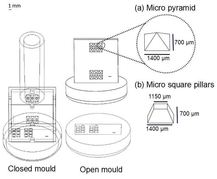
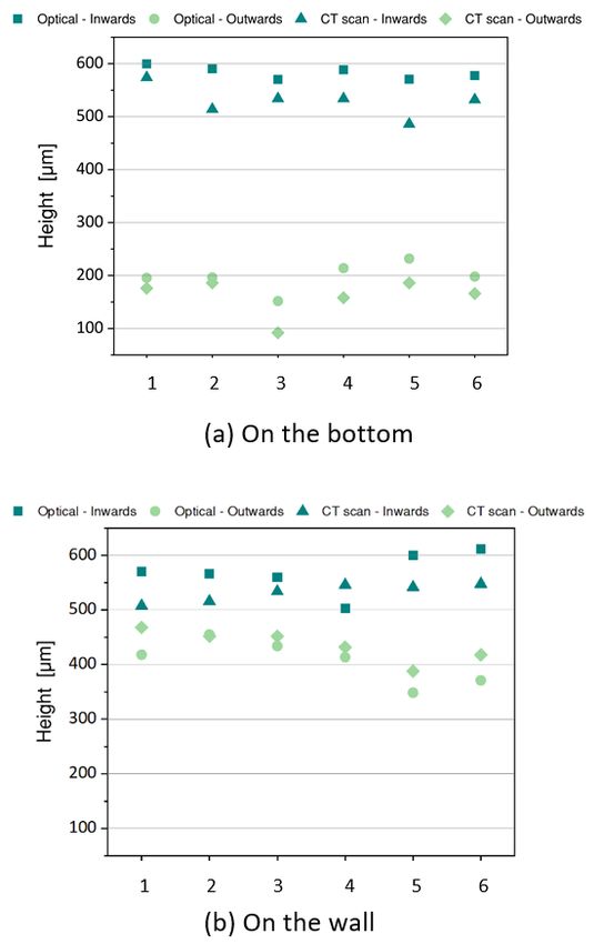
mould, or insert, is fabricated via vat polymerization using a Peopoly Moai SLA printer. Vat polymerization is an additive manufacturing technique where a photopolymer, or a light- activated liquid resin, is cured when it is exposed to UV-light. In Figure 1: The 3DIMS process chain. the present process chain, a water-soluble photopolymer is used, allowing to dissolve the mould in an alkaline solution. The photopolymer used is IM 2.0 produced by Addifab. After the production of the mould, hereafter called insert, the additive manufactured insert is positioned inside a metal mould in an injection moulding machine. The injection moulding machine used is a Nissei THM7, the feedstock is melted at a temperature Figure 2: Closed mould with pyramid structure on the left, two open of 90°C and the mould temperature is set at room temperature moulds for optical measurements on the right. Another version with (23°C). Since the injection is done into a polymeric insert with micro square pillars was also created to study the degree of replication thin walls, the feedstock injection pressure needs to be relatively in the process chain. low, specifically 20 bar, to avoid distortion of the 3D printed printed batch. Figure 2 , on the left, shows the design for the mould during the injection. In order to use low injection pressure closed insert. The cylindrical part of the insert is the sprue with a new feedstock for PIM processes was developed. The used the injection gate location. Two groups of six micro pyramids feedstock has a solid loading of 60% in 316L stainless steel and a with nominal height of 700 µm each are presented on both the specifically designed binder system with low viscosity. After the vertical wall and on the bottom, in each group three pyramids injection, the filled insert is removed from the mould. The are pointing out (outwards pyramids) and three in (inwards conventional ejection of the part is not carried out in the pyramids). The square insert has the same overall mould injection moulding machine but in an additional step: the mould configuration as the previously described pyramid insert. Figure dissolution. The printed insert, filled with the metal feedstock, is 2 (b) shows a detail of the design of the square insert. Six square dissolved in an alkaline solution. The binder system of the pillars and six square holes with height and depth of 700 µm feedstock was designed to withstand the dissolution process were designed on the vertical wall and bottom part of the cavity without causing any geometrical distortion of the part. Once the in the insert. insert is dissolved, the green body is obtained. At this stage, the binder system needs to be removed from the green body. i.e. 3.Measurements debinding. The debinding process is done in two steps: chemically and thermally. First, the green body is treated 3.1 Deviation from optical microscopy to CT chemically in n-heptane for 24 hours at 50°C, and then is As aforementioned, it is not possible to measure directly the thermally treated with the heating cycle described in Table 1. dimensions of the micro features on the closed insert with After is sintered at 1360°C in a protective atmosphere to avoid optical microscopy. Therefore, CT is used to investigate height oxidation. and width of the microstructures without damaging the mould. In this section the height of the micro pyramids of the open Table 1: Heating cycle of the thermal debinding processs. inserts in Figure 2 were first measured with a Werth CT-scan (pixel size of 51 µm), and then measured again with an Olympus Temperature Heating rate Time [h] LEXT 4100 confocal laser-scanning microscope. This 20°C 230°C 2°C/min 1:45 investigation is done in order to identify the best characterization method to evaluate the geometrical deviation 230°C 230°C hold 1 in the process chain. 230°C 500°C 1°C/min 4:30 Figure 3, shows the variation of the height and depth of micro 500°C 500°C hold 3 pyramids on the bottom and on the vertical wall. The dimensions 500°C 20°C - - of inwards and outwards pyramids seem to be more stable for the microstructure printed on the bottom of the insert. The standard deviation of the height of the inwards pyramids on the 2.2. Sample design bottom is 11 µm, while the one for the pyramids on the vertical Two different set of features are used in two different moulds. wall is 35 µm, similar deviations are found for the outwards The investigation of the geometrical dimension of the mould via pyramids. The structures on the bottom are parallel to the optical microscopy and CT is done using moulds with micro printing layer, meaning that the accuracy of the printing pyramids, referred as pyramid insert; the degree of replication depends on the motor of the building plate (resolution of 25 µm is investigated using an insert with square tapered pillars and on z-direction). On the other hand, the micro pyramids on the holes, hereinafter called square insert. wall are perpendicular to the printing direction. In this case, the Since the microstructures are located on the inner surfaces of resolution of the printer depends on the laser (resolution on the the mould, it is not possible to measure directly the dimensions xy-direction is 70 µm), which is lower than the resolution of the of the pyramids with optical microscopy without ruining the motor. insert itself. In order to overcome this problem, two open moulds were printed together with the closed insert for every

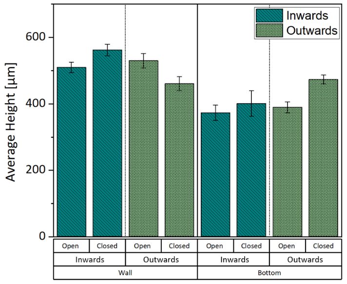
Looking now at the height of the pyramids, it is noticeable 3.2 Deviation from open to close mould
how, for both bottom and wall, the height of the inwards In order to investigate the microstructures with the optical
pyramids is closer to the nominal value of 700 µm. The height of microscope without damaging the insert, the optical
outwards pyramids, instead, deviated from the nominated value measurements were done on the open moulds depicted in
largely because the tip part could not be printed; it is relative Figure 2. The open moulds are used as measurement artefacts
easy to print a hole with a sharp tip than to print a pillar. This is and is necessary to evaluate the deviation from open to closed
particularly true for the outwards pyramids in the bottom. mould to quantify a potential source of error. After a mould is
 manufactured, it requires an additional UV-curing step, to
 finalize crosslinking. The microstructures on the closed mould
 are situated in the inner surfaces, thus they are subjected to
 fewer irradiation to UV-light in comparison to the
 microstructures on the open moulds. The higher the degree of
 curing the higher is the shrinkage [13]. This phenomenon can

 Figure 4: Average height of micro pyramids on the wall and bottom in
 the open and closed mould respectively. Error bars indicate the standard
 deviation of the height calculate from six pyramids.

 cause deviation between open and closed mould. The
 evaluation of the deviation is done by measuring the height of
 the micro pyramids of a closed insert that was cut and measured
 with the optical microscope and the equivalent microstructures
 on the two open moulds.
 Figure 4 depicts the average height of the microstructures in
Figure 3: Height and depth of the micro pyramids measured with the
 open and closed moulds for bottom and vertical walls. The
optical microscope and CT scan for both inwards and outwards pyramids
 overall deviations do not follow a noticeable trend; thus, it is not
on the bottom and on the wall.
 possible to make any assumptions about the error generated by
 Looking at the difference between CT an optical microscope in using open mould as a measurement artefact. However, taking
Figure 3, it is noticeable that in almost all the cases the value of into account the measurements uncertainty and the
the height measured through optical method is higher, the only repeatability of the pillars, the deviation between open and
exception is for the outwards pyramids on the wall. The closed mould can be considered small. Hence, the open mould
resolution of the optical microscope on the z-direction is 10 nm can be used as measurement artefact to evaluate the dimension
and the CT pixel size is 51 µm. The variation between the height of the features in the closed insert.
value calculated with the optical microscope and CT is
approximately 10%. The measurement uncertainty was 4. Replication rate in the process chain
estimated taking both machine error and process into account,
 The validation of the fingerprint concept is carried out by
using the following equation:
 correlating the overall height and width of the moulded part
 2
 = ∙ � + 2 (1) with the dimensions of the microstructures. The overall
 dimension of the printed inserts and moulded parts were
The uncertainty of the height measured with the optical
 measured with a CMC DeMeet 220 (maximum permissible error
microscope is 8.1 µm. The results between CT scan and optical
 4.1 µm). This study was done using the square insert (Figure 2b),
microscope are quite similar, however, considering the higher
 measuring height and width of pillars and holes in the bottom
resolution of the optical microscope, time needed to carry out
 and vertical wall of the mould, and their respectively negative
the investigation and equipment availability, it was decided to
 structure on the part (i.e. a pillar on the mould is a hole in the
investigate the dimensions of the micro features using optical
 part).
microscopy.
 The bar chart in Figure 5 (a) depicts the degree of replication
 of the height of the microstructures and the overall height of the
 part during two consecutive steps of the process chain:
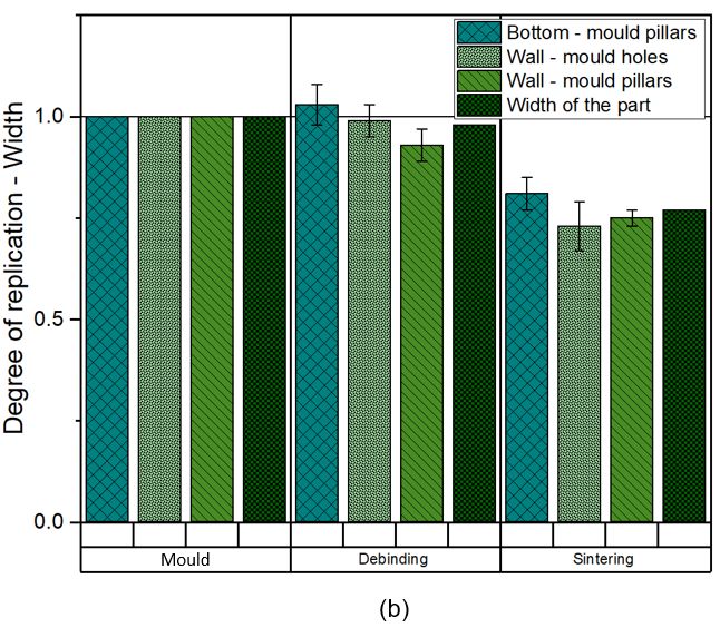
debinding and sintering. The precedent step, i.e. demoulding, is 5. Conclusion
not possible to assess because the paraffin wax present in the
injected slurry settles over the surface veiling the features. The This work describes a novel process chain for metal powder
degree of replication is calculated as follow: injection moulding (PIM), which is particularly valuable for
 Dimension on the part prototyping and manufacturing of highly customized part with
 Degree of replication = (2) complex structures.
 Dimension on the mould
 a Both optical microscopy and computed tomography (CT) were
 From Figure 5 (a) is possible to see how the degree of the investigated in order to identify a possible characterization
replication of the height of the mould pillars (i.e. holes in the method for the process chain. Considering the measurements
part) does not match the replication of the overall height of the uncertainty, time needed to carry out the investigation and
part after debinding. Considering the low strength of the mould accessibility to the equipment, optical microscopy was identified
material, the pillars in the mould might be compressed by the as the most suitable tool to evaluate the geometrical
pressure during the injection of the feedstock, explaining the displacement in the production steps.
low degree of replication for such features after the debinding This paper has also evaluated the use of open moulds as
step. After sintering, the pillars on the mould (holes in the part) measuring artefacts to study the dimensions of micro features
have similar degree of replication to the overall height of the in the closed mould. The investigation showed small deviation in
part. Nonetheless, since it was not possible to find a correlation the value of the height between the microstructures in the open
between height of microstructure and overall height of the part and closed mould, allowing the use of the open moulds as
during the debinding step, the fingerprint concept as quality measuring artefact.
indicator for the process chain cannot be validated. The final aim of this paper was to validate the fingerprint
 On the other hand, the graph in Figure 5 (b) shows similar concept as quality indicator throughout the process chain. It was
degree of replication between the width of the microstructure demonstrated that by solely measuring the width of the
and the overall width of the part for both debinding and microstructures the geometrical stability of the whole part can
sintering. It is thus possible to use the fingerprint concept to be validated quantitatively after debinding and sintering.
correlate the overall quality of the part by investigating the
width of the microstructures. Acknowledgement

 The work has been supported by Innovation Fund Denmark
 through the project “3DIMS – 3D-Printing Integrated
 Manufacturing System” (Grant no. 6151-00005A).

 References

 [1] Atre S V, Weaver T J, and German R M. 2010 SAE Technical Paper
 Series.
 [2] Chartier, T., Delhomme, E., Baumard, J. -F., Veltl, G., & Ducloux, F.,
 2001. Injection Moulding of Hollow Silicon Nitride Parts Using
 Fusible Alloy Cores. Ceram Int, 27 (7): 821–27.
 [3] Zhang, S. -X., Ong, Z. Y., Li, T., Li, Q. F., & Ng, F. -L., 2010. Feasibility
 Study on Producing Components with Embedded Channel by
 Powder Injection Moulding, Key Eng Mater, 447: 401–5.
 [4] Hein SB. 2018, Lost-Form Powder Injection Moulding - Combining
 Additive Manufacturing and PIM, Euro PM 2018-PIM processing.
 [5] Tosello G, Charalambis A, Kerbache L, Mischkot M, Bue Pedersen D,
 Caloan M and Nørgaard Hansen H. 2019 The Int. J. of Advanced
 Manufacturing Technology. 100 783-795.
 [6] Zhang Y. Bue Pedersen D, Mischkot M, Caloan M, Baruffi F and
 Tosello G 2018 J. of Visualized Experiment . 138.
 [7] Zhang Y. Bue Pedersen D, Segebrecht Gøtje A and Mischkot M 2017
 J. of Manufacturing Processes. 27 138-144.
 [8] Mischkot M, Nørgaard Hansen H and Bue Pedersen D 2015
 Proceedings of Euspen´s 15th International Conference & Exhibitions.
 [9] Zhang S, Zhou Y, Zhang H, Xiong Z, To S. 2019 Advances in ultra-
 precision machining of micro-structured functional surfaces and
 their typical applications, Int.J. of Machine Tools and Manufacture.
 142, 16-41.
 [10] Giannekas, N. 2018 Precision Injection moulding of micro features
 using integrated process and product quality assurance. PhD Thesis.
 21-36.
 [11] Calaon, M, Hansen, H. -N, Tosello, G., Garnæs, J, Nørregaard, J, &
 Li, W. 2015, Microfluidic chip designs process optimization and
 dimensional quality control, Mirosyst Technol, 21(3), 561–570.
 [12] Giannekas, N, Kristiansen, PM, Zhang, Y, & Tosello, G. 2018,
 Investigation of product and process fingerprints for fast quality
 assurance in injection molding of micro-structured components.
 Micromachines, 9(12), 661.
 [13] Silikas N, Eliades G, and Watts DC, 2000, Light intensity effects on
 resin-composite degree of conversion and shrinkage strain, Dental
Figure 5: Replication rate in the process chain of: height of the overall
 Materials 16, 292-296.
part and height of microstructure in (a), and overall width of the part
and width of the microstructure in (b).
You can also read