Evaluation of a Retrieved Pyrolithic Reactor to Be Used in Small Farms
←
→
Page content transcription
If your browser does not render page correctly, please read the page content below
Journal of Agricultural Science; Vol. 10, No. 7; 2018
                                                                                ISSN 1916-9752 E-ISSN 1916-9760
                                                               Published by Canadian Center of Science and Education

           Evaluation of a Retrieved Pyrolithic Reactor to Be Used in
                                  Small Farms
             Helder José Costa Carozzi1, Carlos Eduardo Camargo Nogueira1, Thaís Caroline Gazola1,
                    Francielle Pareja Schneider1, Jair Antonio Cruz Siqueira1 & Diogo Giomo1
1
    Universidade Estadual do Oeste do Paraná, Cascavel, Paraná, Brazil
Correspondence: Carlos Eduardo Camargo Nogueira, Universidade Estadual do Oeste do Paraná, Rua
Universitária, 2069, Jardim Universitário, Cascavel, Paraná, CEP: 85.819-110, Brazil. Tel: 55-45-3220-7404.
E-mail: carlos.nogueira@unioeste.br

Received: April 20, 2018          Accepted: May 27, 2018         Online Published: June 15, 2018
doi:10.5539/jas.v10n7p409             URL: https://doi.org/10.5539/jas.v10n7p409

Abstract
The aim of this paper was to evaluate the energy efficiency of a small Generator Motor Group (GMG), driven by
internal combustion (fueled with water and gasoline), using pyrolytic reactor technology (GEET). In order to
achieve this, the pyrolytic reactor was designed and built, so that when in operation, it obtains extra energy
necessary for the pyrolysis process from the thermal energy produced by the combustion of the exhaust gases. In
order to determine the efficiency of the small GMG, in conjunction with the GEET, two experiments were
carried out: the first one was characterized by the operation and use of the GMG equipped with a carburetor, and
when in use it used only ordinary gasoline as fuel. The second experiment was characterized by the insertion of
the pyrolytic reactor, which allowed the motor generator group, when in operation, to use water and gasoline as
fuel, according to the proportions defined in the methodology. It was possible to verify that the engine, when
reaching the voltage near the nominal (115Vac), for the same type and value of load fed, the GEET device
presented, during the tests, high and low efficiency results, showing that the experiment is promising, but
requires more work and more investigations for correct evaluation of the phenomena observed.
Keywords: efficiency, pyrolytic reactor, fuel
1. Introduction
Global energy consumption has nearly doubled in the last three decades. In the United States alone, the increase
was around 35%. It is estimated that over the next 20 years, energy consumption is expected to rise at nearly a
100% rate in developing countries. This increase in energy is also occurring in rural areas, due to the
implantation of several kinds of agroindustries, which aim to benefit and transform agricultural raw materials
into final products with higher commercial value. In many small farms located in Brazil, it is very common the
use of Motor Generator Groups (GMG). In this context, a possible solution for improving the efficiency of this
energy generation would be using the GMG-with fossil (gasoline) or renewable (ethanol)
hydrocarbons-associated with water, as an adjunct fuel element, through the use of the pyrolytic reactor feedback
(GEET-Global Environmental Energy Technology) (Hinriches, Kleinback, & Reis, 2010; Lovins, 2013).
This reactor, during the process of burning the fuel, provides pressure and temperature to the water, breaking its
molecule in its fundamental elements: Hydrogen and Oxygen, fuel and oxidizer, in a process of feedback,
allowing the burning of the Hydrogen gas along with the conventional fuel (gasoline). The process has the
following advantages: a) emission reduction of pollutants, b) lower global warming of the engine, c) increased
efficiency of the lubrication system, with consequent increase in the functional durability of the lubricating oil
and the internal combustion engine, mainly, d) reduction in fuel consumption (gasoline), for the same work
(Martz, 2001; Naudin, 2005).
The general aim of this study was to evaluate the energy efficiency of a GEET device using in a small generator
set. Comparison tests of the energy consumption were carried out between the conventional carbureted system
and the proposed system.

                                                       409
jas.ccsenet.org Journal of A
Agricultural Sciience Vol. 10, No. 7; 2018
1.1 Enginees
Machines that produce mechanical
m eneergy as from other types of eenergy are calleed motors (Hooma, 2009; Zufffo &
Wolff, 19990). Some typees of engines aand their conveersion processees can be obserrved in Table 11.
Table 1. Enngines regardiing to input energy (Homa, 22009)
Enginees in General
Enginee type Power Supply Converssion Type
Electriic Electrricity Rotationnal axis
Internaal Combustion Hydroocarbon Rotationnal axis
Reactiion Hydroocarbon Propulsiion-exhaustion oof gases under ppressure.
All enginees that transforrm heat energy into mechannical energy arre called therm mal motors. C
Combustion eng
gines
can be classsified in exterrnal combustioon engines andd internal combbustion enginees (Homa, 20099).
External tthermal combuustion engines have the chharacteristic oof burning extternal fuel to the engine. Their T
technical aadvantage is thhat they can acccept any typee of fuel, but tthey have the ddisadvantage tthat they cannot be
used in ceertain applicatiions, like aircrraft, due to theeir excessive w
weight (Homa,, 2009; Steam Engine Opera ation,
2016).
Internal ccombustion enngines have tthe characteriistic of burniing the fuel inside the enngine. They have
technologiical advantagees regarding tto the power--to-weight ratiio, which givees them advaantages in posssible
aeronauticcal applicationns, among othher (Homa, 2009). P Theyy can be classsified accordiing to the typ pe of
movementt, in rotary [turrbines, gas turbbines and Wannkel (Albuquerrque, 1976)], aand alternativee (the piston).
mparting smalll air masses at high
In the casee of rotary enggines, these caan be reaction engines, charaacterized by im
speeds (Hooma, 2009; Anntonini, 2000). They may alsso be of the W Wankel Cycle (Albuquerque, 1976), which have
as their chharacteristic coonstructive parrallel axes, in which two boodies, one inside the other, rotate in the same
direction aaround their reespective axess, but with disstinct speeds, giving rise to chambers witth variable volume
(Figure 1)..
Accordingg to Albuquerqque (1976), in this type of enngine, the partts are subject oonly to rotary movements, which
w
represent an advantage:: this engine iis lighter, morre compact annd it consists of a smaller nnumber of parts if
compared to a piston enggine.
F
Figure 1. Wankkel rotary engiine adapted froom Albuquerquue (1976)
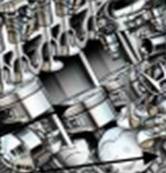
As alternative engines, there
t are pistonn engines. Thiss type of enginne takes advanntage of the eneergy of burnin
ng the
fuel insidee a cylinder, where
w the commbustion gases drive a pistonn (Figure 2), w whose movem ment is transformed
into rotatioonal movemennt through a coonnecting rod aattached to a crrankshaft (Homma, 2009; Albuuquerque, 1976).
410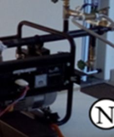
jas.ccsenet.org                            Journal of A
                                                      Agricultural Sciience                     Vol. 10, No. 7; 2018

             Figure 2. Exaample of a pistton engine-Hoonda Accord 3..0 VTEC (Danniels & Danielss, 2007)

The mainn parts of an internal com
                                 mbustion enginne, from the piston type, can be obseerved in Figu
                                                                                                ure 3
(Albuquerrque, 1976).

                           Figure 3. M
                                     Main parts of a ppiston engine ((Albuquerque,, 1976)

Basically, the process by
                        b which thee transformatioon of heat ennergy into meechanical enerrgy occurs ca
                                                                                                      an be
adequatelyy understood, by
                        b means of Fiigure 4.

                                                         411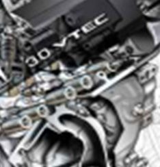
jas.ccsenet.org                               Journal of A
                                                         Agricultural Sciience                        Vol. 10, No. 7; 2018

                      Figuure 4. Heat eneergy transform
                                                      mation in mechanics (Albuquuerque, 1976)

The alternative engines have
                         h      well-defiined operating cycles regardiing to the expllosion process. There are eng
                                                                                                                 gines
called Ottoo cycle and Dieesel cycle.
In a gasoliine, alcohol or even Natural Gas Vehicle (N
                                                     NGV) engine, an air-gas (or air-alcohol) orr air-gas-alcohhol or
air-NGV ggas mixture is ignited by an eelectric spark pproduced by thhe spark plug ignition. In a D
                                                                                                  Diesel engine there
are no sparrk plugs, and gasoline
                         g        (or alccohol or NGV                              Albuquerque, 1976).
                                                    V) is replaced bby diesel oil (A
The ignitioon in a diesel engine is cauused by comprression, whichh causes the aiir temperature in the combu       ustion
chamber too rise so that itt reaches the point of self-ignnition of the fuuel (Albuquerqque, 1976; Hennnessy, 2011).
1.2 Carburretor
The carburretor is a devicce that in geneeral provides ccontrol and adjjust to the amoount of air, dossing the gasoline in
the correctt proportion annd, as a result, it adapts the ddifferent operattional phases oof the internal combustion en
                                                                                                                     ngine:
idling, accceleration and working regiime, accordingg to the operaational necessiity. If the air-ffuel mixture is not
suitable foor the desired or desired opperation, the eengine may sttop due to lacck or excess ffuel (Homa, 2009;     2
Albuquerqque, 1976). A variation
                          v          of thee conventionall carburetor is the injection ccarburetor, whiich is characterized
by its worrking along with
                        w a pump, w      which suppliess the device w   with fuel underr pressure. In this case, only y the
dosing of ffuel and oxidizzer with the prroper amount of air admittedd by the enginne is left to the carburetor (H  Homa,
2009; Albuuquerque, 1976).
1.3 Gasoliine
From the ffuels currentlyy available, gaasoline is the m
                                                       most widely em
                                                                    mployed nowaadays. The daiily consumptio on of
gasoline inn the United States
                         S       of America, in 2009, had an averagge of more thaan 350 millionn gallons, whiich is
equivalentt to approximaately 1324.894 million liters (1US gal = 3.7785412L) (Broown & Holme,, 2009). Gasoliine is
actually a complex blennd, and its com  mposition connsists of more than 100 diffe
                                                                                ferent chemicaals. Its compossition
varies withh the variationn of some parameters, such as the gas coontent, geograpphical locationn and period of
                                                                                                             o the
year.
However, its main com  mpounds are hydrocarbonss-molecules coontaining onlyy carbon atom      ms and hydro ogen.
Predominaantly, such moolecules characcterize the alkkanes, compouunds whose atooms are joinedd by simple bo
                                                                                                           onds.
Many of tthe alkanes in gasoline conttain between 6 and 11 carbbon atoms, thee general form mula for any allkane
being CnH2n+2, where n is
                       i an integer.
In the proocess of burnning gasoline in an internaal combustion engine, the various comppounds present are
simultaneoously subjecteed to the combbustion process, presentingg reactions witth oxygen andd other constituent
elements oof atmosphericc air (Brown & Holme, 20099; Henry, 2011)). The simplesst possible moddel, for the purrpose
of analyzinng the combusstion process, is to take intoo account a sinngle compoundd, which is ussed to represen
                                                                                                              nt the
         mixture, which is the octane C8H18.
gasoline m
Considerinng that gasolinne can be reppresented withh reasonable aapproximationn by octane, thhe description  n and
balancing of the reactionn is not so com
                                       mplex. Therefo fore, taking fulll combustion into account, octane and ox
                                                                                                              xygen
may be evvidenced as reaactants, and carrbon dioxide aand water as prroducts (Brownn & Holme, 20009).
Considerinng that in the United States of America,, in many of its States (Brrown & Holm
                                                                                       me, 2009), tests are

                                                            412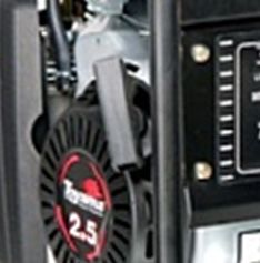
jas.ccsenet.org                             Journal of Agricultural Science                       Vol. 10, No. 7; 2018

required to measure the levels of carbon monoxide and hydrocarbon emissions, as well as other compounds in
the exhaust process of the engines, the presence, especially of hydrocarbons in the exhaust, indicates that a part
of the gasoline passed through the motor cycle without igniting. However, there may be another situation due to
the lack of atmospheric air with adequate concentrations of oxygen, giving the conditions to the appearance of
incomplete combustion (or burning), having CO as a byproduct instead of CO2.
The engine temperature is an important parameter to the correct operation of the engine. An appropriately
regulated engine ensures that full combustion is maximized, it also limits CO emissions, and improves gasoline
fuel consumption per kilometer.
1.4 Pyrolysis
Pyrolysis represents a decomposition reaction by means of heat. In industry, this method is called calcination. It
is possible to produce products through this process, such as bio-oil or pyrolytic tar, as well as charcoal, which
can be regarded as alternative fuels.
From the pyrolysis of some petroleum refining residues, it is possible to (benefit from them almost entirely) take
advantage of them almost in their entirety, resulting in great savings. In this case, the process is also called
cracking, where the long chain molecules are broken down into smaller molecules (Fogaça, 2016).
1.4.1 Pyrolytic Reactor
The chemical reactor, called the pyrolytic reactor, is the main device applied in the process of industrial pyrolysis.
It has three specific areas, namely: drying zone, pyrolysis zone and cooling zone (Fogaça, 2016). The case of
water dissociation, by temperature, occurs in two phases (Expressions 1 and 2):
                                                    H2O → HO + H                                                  (1)
                                                      HO → H + O                                                  (2)
1.4.2 Pantone Reactor
According to (Naudin, 2005; Munsey, 2016), the multi-fuel processor is a new technology, attributed to Paul
Pantone. The system enables common 4-stroke engines to run on water/hydrocarbon blends, more accurately
described as water/gasoline. Under certain conditions of (a specific) regulation of the device and engine, as it is
explained (Naudin, 2005), in an Otto cycle engine, all types of fuels are allowed to be burned: petrol, diesel,
kerosene, other crude petroleum oils, derived from hydrocarbons, using the multi-fuel processor, which is
characterized as an endothermic plasma reactor.
The multi-fuel processor also allows a significant reduction of the pollution generated by the exhaust gas (about
85%) compared to a conventional motor (Martz, 2001; Naudin, 2005).
Preliminary tests conducted by industry professionals and other researchers (Martz, 2001; Naudin, 2005) have
demonstrated that it is possible to make an internal combustion engine (Otto or Diesel cycle), equipped as the
Paul Pantone multi-fuel processor, work properly with a mixture of hydrocarbons (gasoline) at 20% and water at
80%.
The multi-fuel processor consists basically of three main parts (Naudin, 2005): the connection inlet/exhaust
systems, the endothermic reactor (with the magnetic rod and the pyrolytic chamber), and the bubbler. According
to (Naudin, 2005), after the installation of the multi-fuel processor (or endothermic plasma reactor), the
carburetor and conventional silencer (and catalyst) are no longer required.
In Figure 5, it is possible to observe the schematic drawing of the multi-fuel processor proposed by (Naudin,
2005).

                                                         413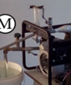
jas.ccsenet.org                               Journal of A
                                                         Agricultural Sciience                         Vol. 10, No. 7; 2018

                  Figure 5.
                         5 Schematic ddrawing of the endothermic pplasma reactorr (Naudin, 20005)

The resultts obtained witth the use of tthe endotherm
                                                    mic plasma, froom the measurement of definned points, suc   ch as
specific coonsumption, different
                       d          flows,, temperaturess, pressures, H2/O2 gas analyysis, resulted in the reductio
                                                                                                                on of
pollutants CO and HC (unburned
                        (           fuell hydrocarbon)). Pollution levvels of carbonn gases have been reduced too 40-
70% levelss (Martz, 20011).
Accordingg to (Martz, 20001), the GEET    T-Pantone proccess is a system
                                                                       m with plausibble potential too mitigate pollution
problems aarising from thhe burning of fossil fuels, w which could beccome a benchm     mark for the m
                                                                                                     market. Howev   ver, it
is clear thaat further studdies-more deptth and more deetailed, concerrning emissionns (nitrogen oxxides, for exam   mple)
are necessary to confirm  m (or not) the C
                                         CO extinguishm ment process, as well as a beetter process-embedded hard    dware,
with reducction of consum   mption. At thee same time, hoowever, it poinnts to the alreaady observed bbenefits in term
                                                                                                                     ms of
heavy mettal pollution, onceo    auto-vehhicles manufaccturers, for deecrease levels of pollution, uuse dangerouss and
expensive heavy metals in catalytic coonverters.
2. Materiaal and Method
                      ds
This workk was carried out in the labboratories of the State Uniiversity of thee West of Parraná (UNIOESSTE),
Cascavel Campus, and in the laboraatories of the University Ceenter of the A   Assis Gurgaczz Foundation-F
                                                                                                         FAG,
Cascavel C
         Campus.
For the prooposed development, we useed a generator group of the T  Toyama brand,, model TF12000CXW1, equiipped
                                                                                  manual startingg, maximum power
with gasolline engine of 2.5 HP (≈ 18665 watts mechhanical), tank oof 5.0 liters, m
of 1.2 kVA
         A, nominal pow wer of 0.95 kV
                                     VA, 110 volts, iin alternating ccurrent (60 Hzz), single phasee (Figure 6).
The Otto ccycle engine, which
                        w                                                          with the OHV (Over Head Valve)
                               is part oof the generatorr motor group, is equipped w                            V
system whhich, accordingg to (Toyama, 22016), is economical, with loow fuel consum mption, fast annd easy starting
                                                                                                                 g.

                                                            414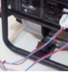
jas.ccsenet.org                              Journal of A
                                                        Agricultural Sciience                       Vol. 10, No. 7; 2018

                          Figure 6. GM
                                     MG Toyama-moodel TF1200C
                                                            CXW1 (Toyamaa, 2016)

A GEET-P  Pantone reactoor was also buuilt to be appplied in this saame motor geenerator groupp. The constru
                                                                                                           uctive
aspects aree next detailedd:
2.1 GEET--Pantone Reacctor, or Multi-F
                                     Fuel Processorr or Endotherm
                                                                mic Plasma Reeactor
Figure 7 shhows the strucctural schematiic design of thee main constituuent parts of thhe GEET-Panttone reactor.
The devicee is composed of two galvannized cylinderss (Items 1 and 2 of Figure 7),, in a coaxial aarrangement, th
                                                                                                                hat is,
one insidee the other. Thhe inner cylindder (Item 2 off Figure 7) haas a 1/2 standaard thread at eeach end, one side
having a leength of 60 mm m (Item 8 of F
                                       Figure 7) and tthe other side hhaving a lengtth of 70 mm (IItem 9 of Figurre 7).
This tube forms the pyroolytic chamberr, whose total length is 695 m  mm, with 15 m mm internal diiameter and 22
                                                                                                               2 mm
external ddiameter. The outer
                          o                          Figure 7) has a standard 1 hhydraulic thread with 25 mm of
                                cylinderr (Item 1 of F
longitudinnal length at eaach end (Item
                                      ms 13 and 16 oof Figure 7), w which is a steeel tube 550 mmm long, 26 mm m of
internal diameter and 344 mm of externnal diameter.
The assemmbly of the twoo cylinders (Iteems 1 and 2 off Figure 7) in a coaxial arranggement is accoomplished by using
                                                                                                                  u
a 1 to 1/2 reducer sleevee (Items 6 andd 7 of Figure 77) with standarrd internal threead of 1/2 andd 1, applied at each
end of the cylinders in quuestion.
Item 4 of FFigure 7 represents the GEE  ET-Pantone connnection duct tto the GMG enngine exhaust duct, constitutting a
standard ggalvanized tube for 1/2 pipee with a 25 mm    m longitudinall length (Item 10 of Figure 7) and 100 mm  m of
total longittudinal length.. This duct hass an elbow of 990° (Item 20 oof Figure 7) of 1/2, which allows the union with
the pipe off 1/2 of diametter (Item 21 off Figure 7), 255 mm of longittudinal length (Item 22 of Fiigure 7). At the
                                                                                                                  e end
of this barrrel (Item 21 of Figure 7) the flange (Iteem 23 of Figuure 7) is weldded, transverseely and inclined at
approximaately 30° for riigid coupling oof the GEET-P   Pantone to the exhaust duct of the GMG. F    Furthermore, Items
                                                                                                                  I
3 and 5 off Figure 7 relatte to the exhauust pipes whicch replace the original exhauust and silenceer of the GMG, and
allow the insertion of thet exhaust reeturn control ddevices to the water and gaasoline mixturre contained in     n the
reservoir/bbubbler GEET--Pantone, and of the fresh airr for the admisssion intake off the GMG sysstem.
The Items 14, 15, 17, 188, 19, 24 and 225 of Figure 7 relate to the fiinal assembly of the structurre, characterize
                                                                                                                  ed by
the solderiing of the com
                        mponents to guaarantee the tighhtness of the aassembly, avoiiding possible leaks, especiallly of
the gases rresulting from the burning off the fuel.

                                                           415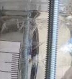
jas.ccsenet.org                              Journal of A
                                                        Agricultural Sciience                        Vol. 10, No. 7; 2018

                               Figure 7. Structural schhematic drawinng GEET-Panttone

The bubbller is characterrized by a gradduated glass veessel (800 ml)), which allows the mixing oof water and fu  uel in
the approppriate proportioons, determineed by the methhodology applied, and allowss closing the reeturn circuit off part
of the fluee gases, creatinng the constantt mixing of gassoline with waater, characterizing bubbling proportional to
                                                                                                                  t the
volume annd speed with which
                           w      gases ennter the vessel (Figure 8).

                                         Figure 8. Mixxing vessel andd bubbler

The princiiple of operatioon of the multti-fuel processsor consists of a self-inducedd plasma geneerator. He conssiders
                                       forming waste into energy, caauses the incom
that a plasma arc, in systems of transfo                                                ming waste strream to be red
                                                                                                                   duced
to its elem
          mentary compoonents (brokenn molecules). T   The multi-fuel processor is ssupposedly cappable of reaching a
plasma staate at a much lower temperrature, and thaat is why an innternal combuustion engine w       with the multii-fuel
processor, proposed by Paul Pantone, could work w      with the most unusual fuels such as gasolline and waterr, just
having hyydrocarbons inn its structuraal chain, such as gasoline, ethanol, dieseel, among othhers (Martz, 2001;    2
Kouropoullos, 1998). All A these fuelss are only coonverted into the same finnal product, the synthesis gas,
characterizzed by combuustion, with soome ease, in thhe combustionn chamber of the engine. Thhere are also some     s
very unusuual aspects of an engine runnning with an eendothermic pplasma reactor,, where the opperating time has   h to
be adjustedd, since an impplosion (controolled detonatioon of fuel) repllaces the exploosive event (M
                                                                                                    Munsey, 2016).

                                                           416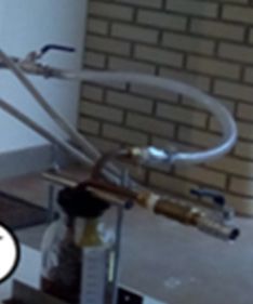
jas.ccsenet.org                              Journal of Agricultural Science                     Vol. 10, No. 7; 2018

The flow of hot gas from the engine exhaust flows through the outside of the reactor (between the inner wall of
the outer tube or cylinder) with a strong kinetic energy, which contributes to raise the temperature very high in
the steel bar-which in this case, acts as a heat accumulator contained in the pyrolytic chamber.
The gases from exhaust, due to burning fuel/oxidizing, internal to the cylinder of the engine, are guided by
external pipelines to the reactor (hydraulic flexible hose of 1/2, for high pressure and high temperature with
stainless steel mesh) and penetrate in the bubbler, containing the water/hydrocarbon mixture. The vapor of the
mixture, in turn, is strongly drawn by the vacuum created by the inlet of the engine (opening of the intake valve
and vacuum caused by the downward movement of the piston in the combustion chamber), and is pushed by the
pressure from the exhaust. The kinetic energy of steam is considerably increased by the reduction of the diameter
on the pyrolytic chamber, which features a circular cross section area of approximately 43.4 mm2. This combined
effect of high temperature and increasing kinetic energy of decomposition produces a thermochemical
(molecular breakdown) from the mixing of water/hydrocarbons, making it possible to obtain higher yielding
fuel.
2.2 Equipment Used for Performing the Tests
For the realization of the tests were used the following equipment (FAG and UNIOESTE):
a)   Portable Digital Anemometer Model-AN-10-Mark-ICEL.
b)   Thermohigrometer-Mark Incoterm-model 7666.02.0.00.
c)   Digital Multimeter-Mark Minipa-model ET-1100A.
d)   Pliers ammeter-model 266 Clamp Meter.
e)   Digital Multimeter and Pliers ammeter-Mark Worker.
f)   Digital tachometer-Mark Instrutemp-Model TTAC-7200.
g)   Digital Infrared Thermometer with Laser Mira-Mark Fluke-Model 59MAX.
h)   Portable Digital Thermometer-model TD800D-Mark ICEL.
i)   Precision weighing scale-Mark Quanta-model QTBB-1000G.
j)   Table weighing scale WH-B11.
k)   Graduated test tube-100 ml-polypropylene base-Mark PHOX.
l)   Chronometer-Mark NAUTIKA-NTK-model PROCRON I.
2.3 Methodology
2.3.1 Scenario 1: Original Carburetor Test
The first scenario was characterized by the use of the original carburetor (without the filter support, to determine
the correct positions of the choke butterfly), as well as gasoline (73% pure gasoline/27% anhydrous alcohol),
additive not (ANP, 2016).
Before each test, the following reference data were recorded:
a)   Local (city, state and country);
b)   Address (street address, number, neighborhood, postal code and additional information);
c)   Date (day, month and year) of the test;
d) Hours (hours and minutes) of the performance of the test determined with chronometer-Mark
NAUTIKA-NTK, model PROCRON I;
e)   Geographical coordinates of the test site using the Google Earth Pro (2017);
f)   Altitude in relation to sea level, through the program Google Earth Pro (2017);
g)   Ambient temperature (°C), near the test site (thermohigrometer-Mark Incoterm-model 7666.02.0.00);
h)   Relative humidity (%), near the test site (thermohigrometer-Mark Incoterm-model 7666.02.0.00);
i) Confirmation of the atmospheric pressure check, based on the measured altitude (Item f) and measured
temperature (Item g) through the online MIDÉ (2017) meter;
j)   Fuel volume in ml (graduated test tube-100 ml-polypropylene base-Mark PHOX);
k)   Mass of fuel (g), using weighing scale in redundancy (Precision weighing scale-Mark Quanta-model

                                                          417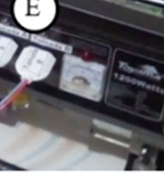
jas.ccsenet.org                              Journal of A
                                                        Agricultural Sciience                    Vol. 10, No. 7; 2018

QTBB-10000G on top off Table weighinng scale WH-B11), both zerroed (tare) alreeady consideriing the mass of
                                                                                                         o the
graduated test tube (Item
                        m j);
l) Volum
       me (ml) of thee crankcase oill, using the rodd of the GMG            Motor Group) iitself-observing the
                                                               G (Generator M
maximum and minimumm points inscribbed in it;
m) Visuaal (color) and tactile
                       t       (viscosiity) verificationn of crankcasee oil characteristics;
n) Tempperature (°C) of the resistiive load bulbb filament, chharacterized byy halogen lam   mps with tung
                                                                                                         gsten
filaments ((W), inert gas and iodine (Diigital Infrared Thermometer with Laser Mira-Mark Flukke-Model 59MA
                                                                                                         AX);
o) Exterrnal temperatuure (°C) of tthe valve covver (Digital Innfrared Therm
                                                                           mometer with Laser Mira-M
                                                                                                   Mark
Fluke-Moddel 59MAX);
p) Exterrnal temperatuure (°C) of thee heat (Digitall Infrared Therrmometer withh Laser Mira-M
                                                                                             Mark Fluke-M
                                                                                                        Model
59MAX);
q) Exterrnal temperatuure (°C) of spark plug ceram
                                                 mics (Digital Infrared Therrmometer withh Laser Mira-M
                                                                                                      Mark
Fluke-Moddel 59MAX);
r) Exterrnal temperatuure (°C) of thhe float bowll of carburetoor (Digital Inffrared Thermoometer with Laser
                                                                                                       L
Mira-Markk Fluke-Modell 59MAX);
s) Exterrnal exhaust duct
                     d    temperatuure (°C)-head/eexhaust interfaace (Digital Innfrared Therm
                                                                                            mometer with Laser
                                                                                                         L
Mira-Markk Fluke-Modell 59MAX);
t) Exterrnal exhaust temperature
                     t           (°°C) (Digital IInfrared Therm
                                                              mometer with Laser Mira-M
                                                                                      Mark Fluke-M
                                                                                                 Model
59MAX);
u) Exterrnal temperatuure (°C) of thee alternator hoousing (Digitall Infrared Therrmometer withh Laser Mira-M
                                                                                                            Mark
Fluke-Moddel 59MAX);
                     o the mass of the fuel at thee initial time off the test (Porttable Digital Thermometer-m
v) Tempperature (°C) of                                                                                      model
TD800D-M
       Mark ICEL).
                                  wing of Scennario 1, demoonstrating the main aspectss of the prop
Figure 9 presents a scchematic draw                                                               posed
configurattion.

                                     wing of Scenariio 1: GMG Tooyama test withh original carburetor
              Figure 9. Schematic draw

One (1) exxperiment was performed forr nominal loadd of 70 W, 1 (oone) test for noominal load of 140 W, 1 (one) test
for nominaal load of 210 W and 1 (onee) test for nom
                                                   minal load of 5660 W. The folllowing variablles were measured,
every minuute, in a total of
                          o 5 minutes peer test:

                                                           418
jas.ccsenet.org Journal of A
Agricultural Sciience Vol. 10, No. 7; 2018
a) Exterrnal temperatuure (ºC) of headd/valve cover;
b) Exterrnal temperatuure (ºC) of headd engine;
c) Exterrnal temperatuure (°C) of sparrk plug ceramiics;
d) Exterrnal temperatuure (°C) of the float bowl of tthe carburetor;;
e) Exterrnal temperatuure (°C) of the exhaust duct oof the head/exhhaust interface;
f) Exterrnal temperatuure (° C) of the exhaust pipe;
g) Exterrnal temperatuure (°C) of the alternator housing, measuredd in the three cconstituent struuctures;
h) Exhaaust gas velociity using a porrtable digital aanemometer m
model: AN-10-m
mark: ICEL, pplaced 30 cm away
a
from the exhaust gas outtlet;
i) Stabiility of rotationn and unchargeed power, using an digital tacchometer-markk Instrutemp-m
model TTAC-7
7200;
j) Variaation of the electrical
e paraameters using,, simultaneoussly, the instruuments: digitaal multimeter-mark
Minipa-moodel ET-11000A, pliers am mmeter-modell 266 clamp meter and digital multiimeter and pliers p
ammeter-m
mark Worker;
k) Fuel consumption at a the nominal speed of 36000 rpm, using thhe time spent ((in seconds) too consume 60 ml
m of
fuel, since the original taank was replacced by a graduaated element w
with a maximuum capacity off 60 ml.
The general configuratioon with load, uusing the origiinal GMG Toyyama carburetoor, can be seenn in Figure 10. The
fuel tank, although closeed at the top, hhas a sigh to m
maintain propeer fuel flow, prreventing presssure difference
e and
consequennt reduction off fuel supply, acccording to thee needs of the GMG during tthe test.
F
Figure 10. Tesst setup with G
GMG load
Note. (A) Test bulbs; (B
B) Fuel tank w
with 1 ml resollution and totaal capacity of 660 ml; (C) Vooltage measurement
point-A annd B sockets-frrom GMG; (D) Generator MMotor Group-G GMG-Toyama-m model TF12000CXW1; (E) Power
outlet-A aand B, from GMG; (F) Digital tachoometer-Mark Instrutemp-M Model TTAC-77200; (G) Digital
Multimeteer-Mark Minipa-model ET-1100A; (H) Diggital Multimetter and Pliers aammeter-Markk Worker; (I) Pliers
P
ammeter-m model 266 Cllamp Meter; ((J) Support aand extension of the speedd meter of thhe Portable Digital
Anemomeeter Model: AN N-10-Mark: ICCEL.
2.3.2 Scennario 2: GEET--Pantone Reactor Test
The seconnd scenario was
w characterizzed by the repplacement of tthe original ccarburetor by tthe GEET-Pan ntone
Reactor, uusing gasoline (73% pure gaasoline/27% annhydrous alcohhol), not addeed together witth water treate
ed by
the local sanitation com wenty-five percent
mpany, mixedd in the mixinng vessel/bubbbler, at a ratioo of 25/75 (tw
gasoline annd seventy-fivve percent wateer), according (Martz, 2001; Naudin, 2005).
Before carrrying out the tests, the sam
me reference ddata already ppresented in Sccenario 1 werre noted. Figurre 11
shows a sschematic draawing, showinng the main cconfiguration aspects that w were proposedd and execute ed in
Scenario 22.
419jas.ccsenet.org Journal of A
Agricultural Sciience Vol. 10, No. 7; 2018
Figure 11.
1 Schematic drawing Scenario 2: assay w
with the GEET
T-Pantone reacttor
For Scenaario 2, a singlee test was perfformed for thee nominal loadd of 560 W, w
with two replicaates (called, in
n this
work, Testt 1 and Test 2). The total innitial volume oof the mixture was 500 mL, being approximately 157 mL m of
ordinary (nnon-additive) gasoline,
g whicch correspondeed to 114.61 m
mL of pure gasooline plus 42.39 mL of anhyd drous
alcohol (999.6% purity), which were added to 343 ml of potablee water. Oncee the initial daata were colle ected,
according to proceduress already desccribed, the sam me variables ppresented in S
Scenario 1 were measured everye
minute, in a total of 5 miinutes per test..
Figure 12 shows the layyout and identtification of G
GEET-Pantone constituent elements, characterized by co ontrol
valves (¼ turn register), control valvees (drawer reggisters), reservvoir/bubbler, coooling system
m radiator reserrvoir,
plus some of the measurrement equipm ment used durinng the tests.
420jas.ccsenet.org Journal of A
Agricultural Sciience Vol. 10, No. 7; 2018
Figure 12. Test cconfiguration w
with load of G
GMG-GEET-Paantone
Note. (A) Control valvee (1/2-inch draawer registratioon) for adjustiing the volumee of gases in tthe mixing/bub bbler
tank (exhaaust duct 1); (B
B) Control Vaalve (¼ turn of 1/2-inch) airr/fuel mixture (post-combustion chamber); (C)
Exhaust ggas duct 1 for the mixing/buubbler reservooir (1/2-inch fl flexible hose w with stainless steel mesh for hot
water); (D
D) Duct 2 of thhe exhaust gasses for the mixxing/bubbler rreservoir (1/2--inch flexible hhose with stainless
steel meshh for hot waterr); (E) Controll valve (1/2-innch drawer logg) of the air/fuuel mixture (gaas and steam) from
the mixingg/bubble reservvoir (pre-reacttor); (F) Contrrol valve (1/2--inch drawer loog) of exhaustt gas flow (exh haust
2); (G) Riigid outlet pipe of the mixinng tank/bubbleer (gas and vaapor fuel); (H)) Flexible ductt (flexible pressure
hose-meshh of 250 psi peer 1/2-inch) innterface (g) wiith (e); (I) Manneuver valve ((1/4 turn 1/2-iinch) control ofo the
vacuum inn the mixing taank/bubbler; (JJ) Test lamps; ((K) Digital Muultimeter and P Pliers ammeterr-Mark Workerr; (L)
Duct (1/2--inch flexible hose with staainless steel m mesh for hot w water-9 mm) ffuel/oxidant innlet valve (n); (M)
Control vaalve (1/2-inch drawer
d log) foor fine tuning aair/fuel mixturee after intake rradiator; (N) M
Mixing tank/bub
bbler
(800 mL); (O) Therrmohigrometerr-Mark Incoterm-model 77666.02.0.00; (P) Digital Multimeter-M Mark
Minipa-moodel ET-1100A A; (Q) Pliers ammeter-moddel 266 Clampp Meter; (R) IIntake radiatorr reservoir (bu ucket
with nomiinal capacity of
o 18 L); (S) R Radiator (1/2-innch aluminum tubing and staandard brass ffittings in hydrraulic
systems).
3. Results and Discussion
3.1 Scenarrio 1: GMG Caarbureted Withh Load
wer (kW) andd consumption (L/h) ratio forr the four (4) eessays carried out (70W/127
Graph 1 prresents the pow 7Vca,
140W/1277Vca, 210W/127Vca and 5660W/127Vca, respectively). In all tests, ccommon gasolline (73% gasoline
and 27% aanhydrous alcoohol) and the same volume (660 mL) were uused.
421jas.ccsenet.org Journal of A
Agricultural Sciience Vol. 10, No. 7; 2018
Graph 1.. GMG carbureeted with testss with load-Pow
wer (kW) × Coonsumption (L
L/h)
aph, when lookking at the maggnitude ratios pplotted, it wass clear that for a greater pow
In this grap wer supplied the
ere is
a direct rellation in the inncrease of the demanded fueel consumptionn. However, coomparing Test 3 with Test 4,, Test
2 with Esssay 3 and Essaay 1 with Essaay 2, it is founnd that, for sm
maller loads, thhe fuel consum mption is higheer. To
demonstraate, assay 3 connsumes, proportionally, 86.23% more fuel to generate thee same kW as Test 4.
Graph 2 rrelates to the Power (kW) ratios with tthe specific C
Consumption (g/kWh) for thhe four (4) essays
performedd.
G
Graph 2. GMG
G carbureted wiith essays withh load-Power ((kW) × Specifiic consumptionn (g/kWh)
Considerinng that the specific consum mption (g/kWh) refers to thee efficiency off the engine too convert fuell into
work, it caan be objectiveely inferred thhat the Essay 4 is the most eefficient in term
ms of the convversion of fuell into
electric poower useful forr the loads connsidered in the respective expperiments. On the other handd, Test 1 is the least
efficient foor the essays performed.
p
MG carburetedd with the 4 (ffour) essays, sshows the relattion of Power (kW) × Efficiiency
Graph 3, rreferring to GM
(%).
422jas.ccsenet.org Journal of A
Agricultural Sciience Vol. 10, No. 7; 2018
Grapph 3. GMG carrbureted with lload essays-Poower (kW) × E
Efficiency (%)
Based on tthe relationshipps plotted, it is evidenced thhat the Essay 4 is the one thaat presents a beetter efficiency
y (%)
in relation to the power (kW)
( generateed. The Essay 11, on the otherr hand, is the onne with the low
west efficiency y (%)
in relationn to the powerr (kW) generaated, and the oother Essays (22 and 3) show w proportionallity in terms of o the
parameterss analyzed. It was
w verified, ttherefore, that GMG presentted a higher yield (%) for a hhigher power value v
(kW) demanded.
3.2 Scenarrio 2: GMG With
W GEET-Panntone With Loaad
O Graph 44, referring to GMG with G GEET-Pantone coupled to a nominal load of 560 W (8 × 70 W/127 Vca), V
gas/water mixture ratio of
o 25/75, withh the 2 (two) teests (repetitionns) performed, has the follow
wing relation Test
T ×
Consumpttion (L/h):
EET PANTON
Graph 4. GE NE and GMG w
with Load-Mixx 25/75-Test × Consumptionn (L/h)
When analyzing Graph 4, 4 it is verifiedd that Test 1 ppresented a low
wer proportionnal consumptioon (0.144 L/h). It is
assumed in this Test that part of the initial volume of water waas converted iinto a fuel equuivalent, or simply
allowed thhe entry of atoomized water into the combbustion chambber, increasing the efficiencyy of the system m by
increasing the compressiion ratio, and ppossible coolinng of the combbustion chamber.
Graph 5 sshows the relaation Test × S Specific consuumption (g/kW Wh) for the saame tests perfformed. The graph g
indicates tthat Test 1 was the most effficient, with a specific consuumption of 2533.91 g/kWh, aand Test 2 wass less
with a specific consumption of 988.73 g/kW
efficient, w Wh, confirminng the results ppresented in thee graph previous.
423jas.ccsenet.org Journal of A
Agricultural Sciience Vol. 10, No. 7; 2018
Graphh 5. GEET PA
ANTONE and G
GMG with Loaad-Mixture 255/75-Test × Speecific consumpption (g/kWh)
Graph 6 ppresents the reelation Test × Efficiency (% %) for the sam me tests perfoormed. The vaalues plotted againa
indicate thhat Test 1 waas the most efficient (32.822% efficiencyy), and Test 2 was the leasst efficient (8.43%
efficiency)). Further testss should be peerformed to re--evaluate thesee results, and tto seek a betteer understandin
ng of
the physicochemical pheenomena that ooccurred durinng the same.
Graph 6. GEET PANTO
ONE and GMG
G with Load-M
Mix 25/75-Testt × Efficiency (%)
4. Conclussions
It was posssible to verifyy, in this workk, the behaviorr of a GMG, w with 2.5 HP gaasoline enginee, submitted to o two
fuel supplyy and control technologies. In the case off the conventioonal essays, w with original caarburetor, whatt was
verified is that the enginne presented, eeven with smaall instabilitiess, functional bbehaviors withiin the expected for
this type oof configuratioon. It was veriified that, for higher load vvalues, the set tends to be mmore efficient, with
proportionnal reduction of the consumpption (L/h) of ffuel per kW geenerated.
As for thee tests perform
med with the GGMG equippedd with GEET-P Pantone, in a m mixture of 25% % of pure gasoline
and 75% oof water, some inconclusive rresults were veerified. In the first test, an effficiency of 322.82% was obtaained,
well above the efficienccy presented bby the carburrized system, for the same load conditionns (9.01%). In n the
second tesst, an efficienccy of 8.43% wwas obtained, slightly below w that presenteed in the carbuurized system, and
well beloww the efficienccy presented inn the previouss test. In this context, more tests should bbe carried out, and
other variaables should bee measured, suuch as CO, CO O2 and total nonn-ignited hydrrocarbons in thhe exhaust gase es, in
order to obbtain more infoormation abouut the results obbtained.
424jas.ccsenet.org Journal of Agricultural Science Vol. 10, No. 7; 2018
References
Albuquerque, C. F., et al. (1976). O livro do automóvel. Seleções do Reader’s Digest (6 th ed.). Lisboa: B&D.
ANP (Agencia Nacional do Petróleo, Gás Natural e Biocombustíveis). (2016). Existe chumbo na composição da
gasolina comercializada no Brasil? Retrieved from https://www.anp.gov.br/wwwanp/fiscalizacao-multas-e-
regularizacoes/247-perguntas-frequentes/consumidores/2712-existe-chumbo-na-composicao-da-gasolina-co
mercializada-no-brasil
Antonini, N. A. (2000). Projeto e construção de motores de combustão interna de êmbolo rotativo (Dissertação
para obtenção do Título de Mestre em Engenharia, Programa de Pós Graduação em Engenharia Mecânica,
Universidade Federal do Rio Grande do Sul, Porto Alegre). Retrieved from file:///C:/Users/Seven/Desktop/
DISSERTA%C3%87%C3%83O%20-%20APOIO/000295528%20-%20MOTORES%20ROTATIVOS.pdf
Brown, L. S., & Holme, T. A. (2009). Química geral: Aplicada à engenharia (1st ed.). São Paulo: Cengage
Learning.
Daniels, B., & Daniels, A. (2007). Automotive illustrators. Accord 3.0 VTEC cutaway engine illustration.
Retrieved from http://www.automotive-illustrations.com/engines.html
Fogaça, J. R. V. (2016). Combustíveis renováveis por meio da pirólise. Brasil, Escola. Retrieved from
https://brasilescola.uol.com.br/quimica/combustiveis-renovaveis-por-meio-pirolise.htm
Hennessy, K. (2011). O livro do carro: enciclopédia visual. São Paulo: Editora Globo.
Henry, D. (2011). 100% hydrogen conversion: For autos, trucks, SUVs (1st ed.). Future Energy Concepts, Inc.
Hinrichs, R. A., Kleinbach, M., & Reis, L. B. (2010). Energia e meio ambiente (4th ed.). São Paulo: Cengage
Learning.
Homa, J. M. (2009). Aeronaves e motores: Conhecimentos técnicos (29th ed.). São Paulo: ASA-Edições Gráficas
Ltda.
Kouropoulos, C. P. (1998). The GEET Demystified. Retrieved from http://rexresearch.com/pantone/pantone.
htm#usp
Lovins, A. B. (2013). Reinventando o fogo: Soluções ousadas de negócios na nova era da energia (1st ed.). São
Paulo: Editora Cultrix.
Martz, C. (2001). Elaboration d’unbanc d’essaiet caractérisations du procédé GEET de P. Pantone à reformage.
Projet de Fin d’Etudes Génie Mécanique option Energétique Industrielleré alisé à l’ENSAIS, Institut
National Des Sciences Apliquées (INSA), Strasbourg, France. Retrieved from http://www.econologie.com/
file/restricted/Rapport_complet_publie.pdf
Munsey, A. (2016). Directory: GEET reactor by Paul Pantone. Retrieved from http://peswiki.com/
directory:geet-reactor-by-paul-pantone
Naudin, J. L. (2005). Tests of a lawn mower retrofitted with the Multi-Fuels Processor (PMC). Retrieved from
http://jlnlabs.online.fr/bingofuel/pmcjlnen.htm
Steam Engine Operation. (2016). How Steam Engines Work. How Stuff Works-Science. Retrieved from
http://science.howstuffworks.com/transport/engines-equipment/steam1.htm
Toyama. (2016). TF1200CXW1. Toyama, Brazil. Retrieved from http://www.toyama.com.br/?menu=produtos&
produto=.&cod=235
Zuffo, J. A., & Wolff, M. M. (1990). Eletrônica: Passo a passo (Vol. 3). São Paulo: Nova Cultural Ltda.
Copyrights
Copyright for this article is retained by the author (s), with first publication rights granted to the journal.
This is an open-access article distributed under the terms and conditions of the Creative Commons Attribution
license (http://creativecommons.org/licenses/by/4.0/).
425You can also read