F783E Ex ia - Opera ng Manual - Food & Beverage
←
→
Page content transcription
If your browser does not render page correctly, please read the page content below
F783E Ex‐ia

Opera ng Manual

Pg 1                            00‐ISN‐203_Rev B
                                      29/01/2021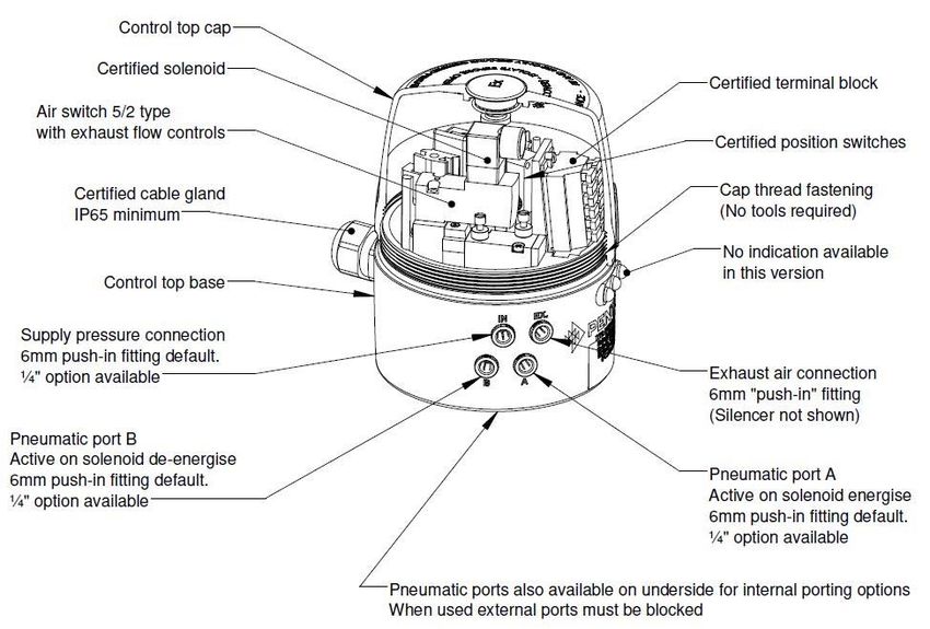
F783E Ex‐ia

DOCUMENT CONTROL
Document Name                                      F783E Ex‐ia Intrinsically Safe
                                                   Opera ng manual
Document Number                                    00‐ISN‐203

Version                                            B

Date                                               29/01/2021

CHANGE LOG
Date             Rev.            Change

25/09/2018       A               New release

29/01/2021       B               Added ATEX approvals

  We reserve the right to make technical changes without notice.
  Technische Anderungen vorbehalten.
  Sous reserve de modification techniques.

  © Pentair Flow Technologies Pacific Pty. Ltd 2018
  Opera ng Manual

Pg 2                                                                                              00‐ISN‐203_Rev B
                                                                                                        29/01/2021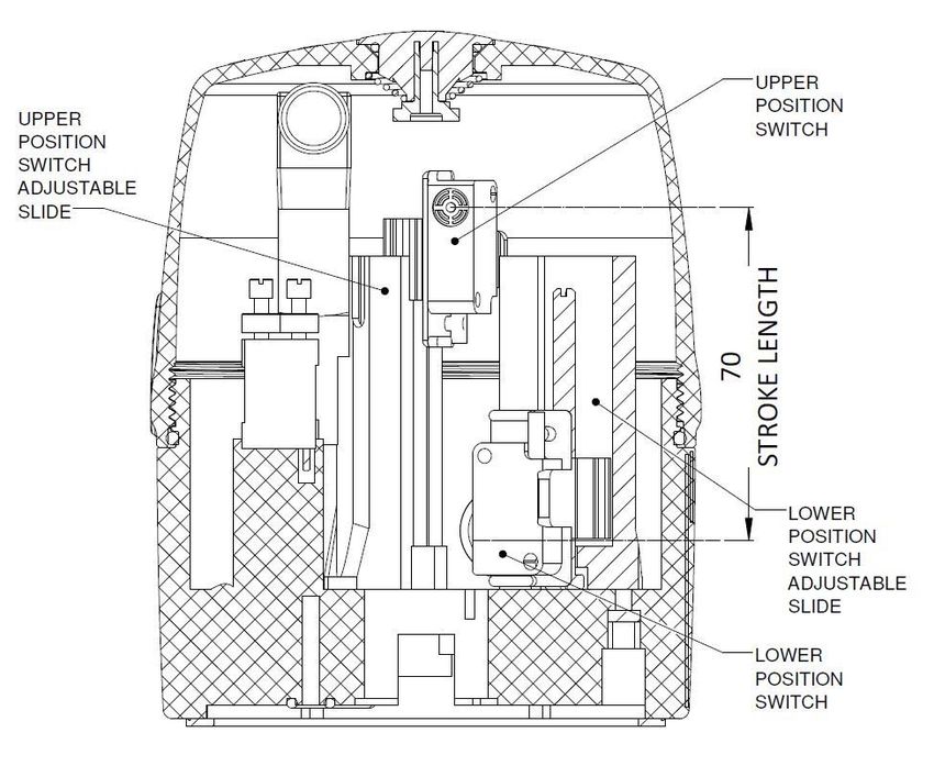
F783E Ex‐ia
        CONTENTS

1. OPERATING INSTRUCTIONS ........................................................................................................................ 6

2. AUTHORISED USE          ........................................................................................................................ 7
        2.1       Export Restric ons ......................................................................................................... 7

3. BASIC SAFETY INSTRUCTIONS ........................................................................................................................ 8

4. GENERAL INFORMATION     ...................................................................................................................... 10
        4.1.      Contact address ............................................................................................................ 10
        4.2.      Warranty ...................................................................................................................... 10
        4.3.      informa on on the internet ......................................................................................... 10

5. CERTIFICATION DETAILS     [START OF CONTROLLED AREA]
         5.1        IECEx     ...................................................................................................................... 11
         5.2        ATEX      ...................................................................................................................... 11
         5.3        Condi ons of Cer ficate .............................................................................................. 12
                             [END OF CONTROLLED AREA]
6. SYSTEM DESCRIPTION         ...................................................................................................................... 14
         6.1.       Intended applica on area ............................................................................................ 14
         6.2.       General descrip on ...................................................................................................... 14
         6.3.       Func ons/op ons/designs ........................................................................................... 15
                    6.3.1 Structure of the control head ........................................................................... 15
                    6.3.2 Fluid diagram .................................................................................................... 16
                    6.3.3 Number of solenoid valves ............................................................................... 17
                    6.3.4 Pneuma c interfaces ........................................................................................ 17
                    6.3.5 Manual control ................................................................................................. 17
                    6.3.6 Posi on monitoring system .............................................................................. 17

7. TECHNICAL DATA                      ...................................................................................................................... 18
        7.1.                  Opera ng condi ons .................................................................................................... 18
        7.2.                  Conformity to the following standards ........................................................................ 18
        7.3.                  Ra ng plate specifica ons............................................................................................ 19
        7.4.                  Pneuma c data ............................................................................................................ 20
        7.5.                  Posi on system data .................................................................................................... 21

8. INSTALLATION                          ...................................................................................................................... 22
         8.1.                 Safety instruc on ......................................................................................................... 22
         8.2.                 Assembly of the control head ...................................................................................... 22
                              8.2.1. Moun ng the base .......................................................................................... 22
                                        8.2.1.1. Fi ng the control head—Linear actuator................................... 23
                                        8.2.1.2. Limit Switch Se ng ..................................................................... 23
                                        8.2.1.3. Fi ng the control head—Rotary actuator .................................. 24
                                        8.2.1.4. Limit Switch and Rotary Target Se ng ....................................... 24
                              8.2.2. Pneuma c and electrical connec ons ............................................................... 24

9. OPENING AND CLOSING THE HOUSING ...................................................................................................... 27
        9.1       Safety instruc ons ........................................................................................................ 27
        9.2       Opening and closing the housing ................................................................................. 27
                  9.2.1     Opening the housing ..................................................................................... 27
                  9.2.2     Closing the housing ....................................................................................... 28

 Pg 3                                                                                                                                                  00‐ISN‐203_Rev B
                                                                                                                                                             29/01/2021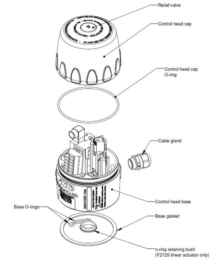
F783E Ex‐ia
        CONTENTS Cont’d

10.     PNEUMATIC INSTALLATION ................................................................................................................... 27
           10.1.     Safety instruc ons ....................................................................................................... 27
           10.2.     Pneuma c connec ons of the control head ................................................................ 27
           10.3.     Flow restric on func on of the solenoid valve ........................................................... 28

11.     ELECTRICAL INSTALLATION .................................................................................................................... 29
           11.1. Electrical connec on op ons ................................................................................................ 29
           11.2. Electrical data ...................................................................................................................... 29
           11.3. Safety instruc ons ................................................................................................................ 30
           11.4. Electrical installa on and start‐up ......................................................................................... 31
                        11.4.1. Cable gland with spring terminals .................................................................. 31

12. DECOMMISSIONING          ...................................................................................................................... 23
       12.1. Safety instruc ons ................................................................................................................. 32
       12.2. Dismantling the F783E control head ..................................................................................... 32

13. DISPOSAL                                 ...................................................................................................................... 33

 Pg 4                                                                                                                                                      00‐ISN‐203_Rev B
                                                                                                                                                                 29/01/2021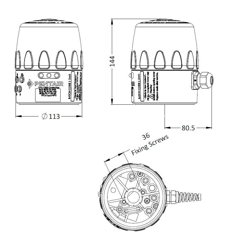
F783E Ex‐ia

This page le blank

Pg 5                               00‐ISN‐203_Rev B
                                         29/01/2021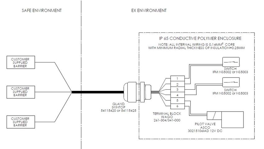
F783E Ex‐ia
The opera ng instruc ons describe the en re life cycle of the device. Keep these instruc ons in a loca on which is easily
accessible to every user, and make these instruc ons available to every new owner of the device.
WARNING!
The opera ng instruc ons contain important safety informa on!
Failure to observe these instruc ons may result in hazardous situa ons.
• The opera ng instruc ons must be read and understood.
Symbols:
DANGER!
Warns of an immediate danger!
• Failure to observe the warning will result in a fatal or serious injury.
WARNING!
Warns of a poten ally dangerous situa on!
• Failure to observe the warning may result in serious injuries or death.
CAUTION!
Warns of a possible danger!
• Failure to observe this warning may result in a moderate or minor injury.
NOTE!
Warns of material damage!
• Failure to observe the warning may result in damage to the device or the equipment.
! Indicates important addi onal informa on, ps and recommenda ons.
Refers to informa on in these opera ng instruc ons or in other documenta on.
Designates a procedure which you must carry out.
Pg 6 00‐ISN‐203_Rev B
29/01/2021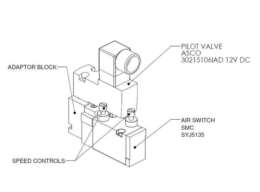
F783E Ex‐ia

Incorrect use of the control head F783 Easymind Ex‐ia may be dangerous to people, nearby equipment and the
environment.
The control head has been designed for use as actua on of pneuma cally operated valves and / or for recording the switching
states of these.
The authorised data, the opera ng condi ons and condi ons of use specified in the contract documents and opera ng
instruc ons are to be observed during use. These are described in Chapter "6. Technical Data".
In view of the large number of applica on op ons, check and, if required, test prior to installa on whether the control head is
suitable for the specific applica on case.
If you are unsure, please contact your Pentair Flow Technologies Pacific Pty. Ltd contact.
The device may be used only in connec on with third‐party devices and components which have been recommended or
approved by Pentair Flow Technologies Pacific Pty. Ltd.
Any unauthorized reconstruc ons and changes to the control head are prohibited for safety reasons.
Correct transporta on, correct storage and installa on as well as careful opera on and maintenance are essen al for reliable
and problem‐free opera on.
For connec ng the control head, use line installa ons that do not cause any mechanical stresses.
Use the device only as intended.

If expor ng the system/device, observe any exis ng restric ons.

Pg 7                                                                                                            00‐ISN‐203_Rev B
                                                                                                                      29/01/2021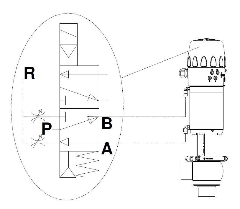
F783E Ex‐ia

These safety instruc ons do not make allowance for any:
Con ngencies and events which may arise during assembly, opera on, and maintenance of the devices.
Local safety regula ons ‐ the operator is responsible for observing these regula ons, also in rela on to the installa on
personnel.

        DANGER!

Danger ‐ high pressure!
Before loosening lines and valves, turn off the pressure and vent the lines.

Danger of explosion when used in explosive atmospheres.
Opening the control top in an explosive atmosphere is only allowed in a non‐energised state
Use only cables and cable glands which have been approved for the respec ve applica on area and which have been installed
according to the respec ve installa on instruc ons. Do not expose the device to any mechanical or thermal loads exceeding
that described in the opera ng instruc ons

        WARNING!

Warning ‐ Risk of electric shock!
Before reaching into the system switch off the power supply and secure it to prevent restar ng!
Observe applicable accident preven on and safety regula ons for electrical equipment!

General hazardous situa ons.
To prevent injuries:
Ensure that the system cannot be ac vated uninten onally.
Installa on and maintenance work, as well as operator control ac ons may be carried out by authorised and qualified
technicians only and with the appropriate tools.
Do not make any unauthorized internal or external changes to the device!
A er an interrup on in the electrical or pneuma c supply, ensure that the process is restarted in a defined or controlled
manner.
The device may be installed and operated only when in perfect condi on and in considera on of the opera ng instruc ons.
The general rules of technology apply to applica on planning and opera on of the device.

Pg 8                                                                                                            00‐ISN‐203_Rev B
                                                                                                                      29/01/2021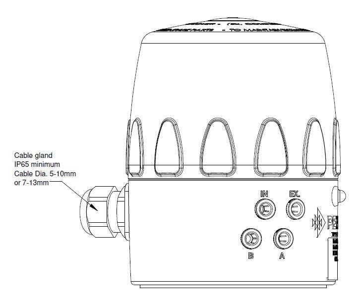
F783E Ex‐ia
NOTE!
Electrosta c sensi ve components
The device contains electronic components which react sensi vely to electrosta c discharge (ESD). Contact with
electrosta cally charged persons or objects may be hazardous to these components. In the worst case scenario, they will be
destroyed immediately or will fail a er start‐up.
Observe the requirements in accordance with EN 61340‐5‐1 to minimize or avoid the possibility of damage caused by
sudden electrosta c discharge!
Also ensure that you do not touch electronic components when the supply voltage is on!
NOTE!
Risk of damage to property
Do not connect any mechanically rigid connec on parts, in par cular those with long lever arms, as such connec ons could
generate torques that might damage the control head.
Do not supply the medium connec ons of the system with liquids or aggressive or flammable media!
Do not subject the housing to mechanical loads (e.g. by placing objects on it or standing on it).
Do not make any external changes to the housings of the device. Do not paint housing parts or screws.
Only use compa ble cleaning agents (e.g. isopropanol up to 70%) for cleaning the securely closed control head and always
rinse thoroughly with clean water.
! Control head F783E Ex‐ia was developed with due considera on given to accepted safety rules and is state‐of‐the‐
art. Nevertheless, dangerous situa ons may occur.
Pg 9 00‐ISN‐203_Rev B
29/01/2021
F783E Ex‐ia

Check immediately upon receipt of the consignment that the contents are not damaged and that the type and scope agree with
the delivery note and packing list.
If there are any discrepancies, please contact us immediately.

          Pentair Flow Technologies Pacific Pty. Ltd
          12‐14 Kaimiro St
          Hamilton 3200
          T: +64 (0) 7 958 7100
          F: +64 (0) 7 958 7101
          E: Email: PacificNZHygienicSales@pentair.com
          Website: h p://foodandbeverage.pentair.com

Please refer to our general terms of sales and business.
The warranty is only valid if the control head is used as intended in accordance with the specified applica on condi ons

 !        The warranty extends only to defects in the control head F783E Ex-ia and its components.

         We accept no liability for any kind of collateral damage which could occur due to failure or malfunction of the device

The opera ng instruc ons and data sheets for F783E control top can be found on the Internet at:

h p://foodandbeverage.pentair.com

Pg 10                                                                                                                             00‐ISN‐203_Rev B
                                                                                                                                        29/01/2021
F783E Ex‐ia
Pentair Flow Technologies Pacific Pty. Ltd
2. Model : F783E Ex‐ia
3. Cer ficate Number : IECEx ITA 11.0016X
4. Ex. Marking Code : Ex ia IIB T5 Ga IP65
: Ex ia IIC T5 Gb IP65
: Ex ia IIIC T90°C Da IP65
5. Ra ngs : IP65, 0°C ≤ Tamb ≤ 40°C
6. Standards : IEC 60079‐0:2011 Ed. 6
IEC 60079‐11:2011 Ed. 6
Pentair Flow Technologies Pacific Pty. Ltd
2. Model : F783E Ex‐ia
3. Cer ficate Number : TÜV 16 ATEX 7985X
4. Ex. Marking Code : II 1G Ex ia IIB T5 Ga
: II 2G Ex ia IIC T5 Gb
: II 1D Ex ia IIIC T90°C IP65 Da
5. Ra ngs : IP65, 0°C ≤ Tamb ≤ 40°C
6. Standards : EN 60079‐0:2012/A11:2013
: IEC 60079‐11:2012
Pg 11 00‐ISN‐203_Rev B
29/01/2021F783E Ex‐ia
It is a condition of safe use that the apparatus must be mounted so that there is a low risk of
mechanical damage.
The Valve Control Top F783E Ex-ia version may only be used as explosion safe after proper
installation to the process equipment (e.g. actuator) either directly or via. a suitable mounting
adaptor so that an ingress protection degree to a minimum of IP65 has been achieved.
The equipment is to be cleaned with a damp cloth to ensure the minimization of electrostatic charge
build up.
The equipment is not to be mounted in direct sunlight
It is up to the user to provide correct barrier components in accordance with the guidelines in this
manual
The maximum ambient temperature the intrinsically safe version of the equipment used in Group
IIIC applications may be increased to 50°C, in which case the temperature classification of T100°C
applies
Pg 12 00‐ISN‐203_Rev B
29/01/2021F783E Ex‐ia
This page le blank
Pg 13 00‐ISN‐203_Rev B
29/01/2021F783E Ex‐ia
The control head F783E Ex‐ia has been designed for use as actua on of pneuma cally operated process valves and / or for
recording the switching states of these.
The control head F783E Ex‐ia is used for actua ng pneuma cally operated hygienic process valves.
For process valve actua on, the control head can be equipped with a single 2/5 solenoid valve.
For the recording and feedback of the process valve switching posi ons to a higher‐level control, the control head has been
equipped with two posi on feedback switches. These are NAMUR style 2‐wire induc ve proximity switches.
The F783E Ex‐ia control head mounts directly on standard Pentair actuators of figure number F257 and F272S. This produces an
integrated, compact and decentralized system of actua on, valve func on and feedback. The following advantages over
centralised solu ons working with valve clusters are achieved:
low installa on expenditure
easy start‐up
shorter switching mes and less air consump on due to shorter distances between the pilot valve and the
process valve.
There is a wide range of moun ng op ons available for many other brand actuators in the hygienic food and beverage industry,
as well as common industrial actuators. Please consult a customer services representa ve for more details on moun ng op ons
available.
Pg 14 00‐ISN‐203_Rev B
29/01/2021F783E Ex‐ia
Fig 1: Structure of the control top
Pg 15 00‐ISN‐203_Rev B
29/01/2021F783E Ex‐ia
Control head F783E Ex‐ia—fluid diagram (with restric on capability for solenoid valve)
Fig 2: Pneuma c circuit for SMC SYJ5315 air switch as installed in the F783E Ex‐ia control head
Pg 16 00‐ISN‐203_Rev B
29/01/2021F783E Ex‐ia
The F783E Ex‐ia control head for process and bu erfly valves has been designed for single‐ac ng and double‐ac ng valve
actuators as well as for double seat and mul ‐posi on valves using a single solenoid valve.
The air switch is a 5/2 type, with common exhaust. Flow restrictors are installed in the exhaust line of both ports, meaning the
opera ng speed of the actuator can be controlled in both direc ons
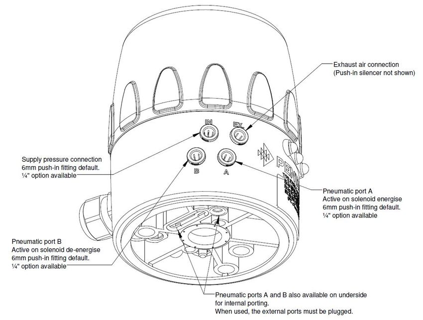
Intake & exhaust air connec ons: 6.0mm “One Touch” push in air fi ngs
Working connec ons: 6.0mm “One Touch” push in air fi ngs or internal por ng op on when fi ed to the
F257 type actuator (for ¼ turn opera on) Integrated flow regulator in the air switch exhaust
air ports
The pilot solenoid valve is provided with a push bu on to operate the pilot valve manually.
The SMC SYJ5153 air switching valve has also a manual operator, which is par ally obscured by the pilot valve, so should not
be used.
The switching posi ons of the actuator are reported to the control system by feedback signals from two switches mounted on
switch pillars within the housing.
The height and orienta on of these switches can be adjusted to accommodate the stroke length of all F257 and F272S type
actuators. This is achieved by adjus ng the screw on the switch pillar to raise or lower the switch and turning the switch
around in the retaining clip.
The ¼ turn actuators use a special adjustable target set to accommodate target rota on between 0 and 180°.
Pg 17 00‐ISN‐203_Rev B
29/01/2021F783E Ex‐ia
DANGER!
Danger of explosion when used in explosive atmospheres.
Opening the control top in an explosive atmosphere is only allowed in a non‐energised state
Use only cables and cable glands which have been approved for the respec ve applica on area and which have been installed
according to the respec ve installa on instruc ons. Do not expose the device to any mechanical or thermal loads exceeding
that described in the opera ng instruc ons
WARNING!
Risk of injury from overhea ng of the control head.
Ambient temperature:
Ex‐ia version: 0° ... +40 °C (Max. 95% humidity; non‐condensing)
General hazardous situa ons.
To prevent injuries:
Ensure that the system cannot be ac vated uninten onally.
Installa on and maintenance work, as well as operator control ac ons may be carried out by authorised and qualified
technicians only and with the appropriate tools.
Do not make any unauthorized internal or external changes to the device!
A er an interrup on in the electrical or pneuma c supply, ensure that the process is restarted in a defined or controlled
manner.
The device may be installed and operated only when in perfect condi on and in considera on of the opera ng
instruc ons.
The general rules of technology apply to applica on planning and opera on of the device.
Degree of protec on:
Ex‐ia version:
IP65 according to EN 60529
(only if cables, plugs and sockets have been connected correctly, the cap has been sealed correctly and the adapta on to the
process valve was done correctly)
Certain variants only of the control head F783 EASYMIND Ex‐ia comply with the EC direc ves according to the EC
Declara on of Conformity. The applied standards which are used to demonstrate compliance with the Direc ves are
listed in the EC Declara on of Conformity. This may be requested from Pentair Flow Technologies Pacific Pty. Ltd.
The specifica ons on the respec ve ra ng plate apply to the respec ve control head. The symbols on the ra ng
plate indicate the applicable direc ves or approvals:
Pg 18 00‐ISN‐203_Rev B
29/01/2021F783E Ex‐ia
Fig. 3: Dimensional drawing – Ex‐ia version
Weight: approx. 0.7 kg
Housing material: exterior: PA66 + PA6, TSC10/4, EC
inside: ABS
Sealing material: exterior: EPDM (O‐rings)
Santoprene (gasket)
inside: NBR
Pg 19 00‐ISN‐203_Rev B
29/01/2021F783E Ex‐ia
WARNING!
Use clean dry air
Do not use compressed air which contains chemicals, synthe c oils containing organic solvents, salts or corrosive gases, etc., as
this can cause damage or malfunc on.
CAUTION!
Install air filter
Install air filters close to valves at their upstream side. A filtra on degree of 5 μm or less should be selected.
Install an air dryer, a er cooler or Drain Catch (water separator) etc.
Air that includes excessive moisture may cause malfunc on of valves and other pneuma c equipment. To prevent this, install
an air dryer, a er‐cooler, or water separator, etc.
If excessive carbon dust is generated
Eliminate it by installing mist separators at the upstream side of valves. If excessive carbon dust is generated by the
compressor, it may adhere to the inside of valves and cause malfunc on.
Control medium: Air, neutral gases
Quality classes in accordance with DIN ISO 8573‐1
(5µm filter recommended)
Dust content Quality class 7: max. par cle size 40µm
max. par cle density 10mg/m³
Water content Quality class 3: max. pressure dew point –20°C or min. 10°C below the lowest opera ng temperature
Oil content Quality class X: max. 25mg/m³
Temperature range
of compressed air: ‐10 … +50° (non‐condensing)
Pressure range: 3.0 … 7 bar (minimum air pressure of system may be higher than minimum pressure to
operate solenoid, as required by product condi ons, valve or actuator)
Connec ons: 6mm “One touch” push‐in fi ngs, collets and O‐rings are replaceable
Fig. 5: Solenoid operated air switch
The exhaust flow rates for both ports can be controlled separately to control the actuator speed in both energising and de‐
energising direc ons
Pg 20 00‐ISN‐203_Rev B
29/01/2021F783E Ex‐ia
Fig. 6: Sec on view of control head on linear actuator
Pg 21 00‐ISN‐203_Rev B
29/01/2021F783E Ex‐ia
For installa on in Ex. situa on: refer to special condi ons in Sec on 5 of this manual. Use only Ex. cer fied product
Always wear the appropriate PPE for the situa on. Use correctly sized tools for opera ons that require tools
DANGER!
Risk of injury from high pressure in the system
•Before loosening any lines and valves turn off the pressure and vent the valves
WARNING!
Risk of injury from overhea ng of the control head.
Before accessing the inside of the F783E Ex‐ia control head, isolate any control power which may be hazardous to the
health of the operator.
Ensure the control head is safe to work on – secure the system against uninten onal ac va on
Avoid leaving live loose wires which can contact ground or each other and ini ate protec ve devices.
When commissioning and tes ng the control head, before manually opera ng the actuator ensure it is safe to do so.
Ensure opera ng the valve won’t compromise personal or product safety. Keep hands clear of moving parts at all mes.
The control head can be installed in any installa on posi on. Ensure there is sufficient height above the control head to
remove the cap and adjust the switches.
The device should be installed such that layers of dust thicker than 5 mm cannot form; meaning that such should
be ensured through correspondingly regular cleaning.
Risk of injury from improper assembly!
Do not improperly stress the control head.
Do not apply any leverage effect on the head and do not climb on it.
For the installa on of the F783E Ex‐ia control head to a linear‐type actuator, you will require an actuator‐specific target. Be
sure to order the correct target for that actuator.
For installa on of the F783E Ex‐ia control head on a rotary‐type actuator, the target will always be the same. Depending on
the type and brand of actuator an adaptor kit may be required.
When moun ng the F783E Ex‐ia control head on a PENTAIR brand F257 or F272S actuator no special moun ng adaptor is
required.
8.2.1. Moun ng the base
NOTE!
Maximum supply cable length is to be 30m. Control top must be installed in the same building as the control cabinet.
Installa on environment and wiring are influen al on the module’s EMC: Thus the installer must secure EMC of the
whole device.
According to Norm EN 61326‐1: 2006 (chart 2) DC supply connec ons to the module are treated as input/output
signal lines. For cable lengths greater than 30 m and outdoor applica ons addi onal measures must be implemented
in order to comply with CE
Pg 22 00‐ISN‐203_Rev B
29/01/2021F783E Ex‐ia
For installa on in Ex. situa on: refer to special condi ons in Sec on 5 of this manual. Use only Ex. cer fied product
8.2.1.1. Fi ng the control head—Linear actuator
If installing on the F272S actuator, remove and discard the metal O‐Ring retaining plate/cover. Fit the O‐Ring retaining
bush (supplied with the actuator) over the actuator sha , small diameter uppermost, to secure the actuator sha O‐Ring.
1. Fit the linear target assembly to the sha of the piston valve actuator. Tighten using a Hex key.
2. The height of the switches have been factory set to operate when used on a F257 1/4 turn actuator, so the Open
switch, which is opposite the solenoid, must be inverted in order to achieve sufficient height adjustment. To do this
turn the switch tower adjus ng screw clockwise un l the switch carrier is flush with the top of the screw. Prise the
holding clip outwards gently un l the switch comes free with a gentle tug. Rotate the switch so the target area is
uppermost and set back into the switch holder, make sure the retaining clip snaps over the switch (see Limit Switch
Se ng below for adjustment procedure).
3. Locate the Base Gasket on to the step on the top of the actuator or moun ng kit adaptor.
4. Fit the two Base O‐Rings into the round & oval recesses in the base of the control head, the larger O‐Ring is supplied
round and will need to be worked into its oval recess. DO NOT apply grease, the O‐Rings will be easier to fit and keep
in place if kept dry and not lubricated.
5. Fit the control head over the target assembly onto the actuator or adaptor plate. Check any moun ng holes do not
foul the Base O‐Rings while orien ng the air ports towards the actuator air ports.
6. Fasten the Control Head down by means of the two M6 socket head cap screws. Torque down to 3.5 NM.
7. Connect the air lines from the actuator to the control head to suit the actuator and valve combina on. Port “B” is live
when the solenoid is de‐energised, the “A” port is live when the solenoid is energised.
8. Connect the air supply to the Control Head port labelled “IN”. If it is safe to do so the actuator can be operated using
the manual override on the solenoid. Check for leaks.
9. Tighten the cable gland firmly using an appropriate spanner.
8.2.1.2. Limit Switch Se ng
This procedure is simplified if the control head is connected to a power source, as the LED’s on the switches (if present) will
indicate. It is best to adjust the switches such that the target is just coming into the switch detec on zone.
1. Operate the valve to the fully OPEN (up) posi on by opera ng the manual override switch on the pilot valve.
2. Using a small flat blade screwdriver adjust the switch opposite the solenoid by turning the height adjustment screw,
clockwise raises the switch, an clockwise lowers the switch. If power is not available align the centre of the target
symbol on the switch with the middle of the metal target.
3. Operate the valve to fully closed (down) posi on. Adjust the switch opposite the terminal block by turning the height
adjustment screw.
4. Release the manual override if used, before fi ng the cap O‐Ring and screwing the cap firmly down.
Fig 7. Moun ng ‐ Linear Components
Pg 23 00‐ISN‐203_Rev B
29/01/2021F783E Ex‐ia
For installa on in Ex. situa on: refer to special condi ons in Sec on 5 of this manual. Use only Ex. cer fied product
8.2.1.3. Fi ng the control head—Rotary actuator
1. Secure the rotary target assembly to the indicator sha of the F257 ¼ turn actuator or actuator moun ng kit. Ensure
the grub screw (set screw) locates into the dimple provided on the drive flat.
2. Locate the rubber base gasket on to the step on the top of the actuator or moun ng kit adaptor.
3. Fit the two O‐rings into the round & oval recesses in the underside of the base of the control head, the larger O‐ring
will need to be worked into its recess. It is be er NOT to apply grease, the O‐ring will be easier to fit and keep in place
if not lubricated.
4. Fit the control head over the target assembly onto the actuator, ensuring the O‐rings in the base of the head line up
with the internal air por ng in the top of the actuator. When the control head is being fi ed to any actuator other
than the F257 ¼‐turn, the external air por ng is used and the adaptor will blank off these ports. Check any moun ng
holes do not foul the O‐rings.
5. Fasten the head down by means of the two M6 socket head cap screws. Torque down to 3.5 NM. Do not over ghten.
6. Fit the two plugs supplied with the rotary target assembly into ports ‘A’ & ‘B’ in the control head.
Note: When the control head is used in an applica on other than the internally ported F257 actuator, Port B is “live” when the
solenoid is De‐energised, and Port A is “live” when the solenoid is Energised.
8.2.1.4. Limit Switch and Rotary Target Se ng
Se ng the switch height:
The height of the switches have been factory set for use on the F257 ¼‐turn actuator. If the control head is fi ed to another
actuator the switch heights may need to be adjusted to suit the target height. The switch to indicate the open posi on is
opposite the terminal block, the switch to indicate closed is opposite the solenoid. The target area of the switches (the
crosshairs) should line up with the metal target cams.
To adjust the switch height, turn the adjus ng screw (through the switch holder) to raise or lower the switch.
Se ng the target cams:
1. Operate the actuator to the fully open posi on, using the manual solenoid control bu on.
2. Slacken the central screw (slo ed head screw) on the rotary target assembly one full turn.
3. Adjust the top cam by turning the adjus ng screw marked ‘OPEN’ with a small flat blade screwdriver so the target is
lined up with the centre of the switch.
4. Operate the actuator to the fully closed posi on
5. Adjust the bo om cam by turning the adjus ng screw marked ‘CLOSED’ using the screwdriver so the target is lined up
with centre of the switch.
6. A er se ng the cams, re‐ ghten the central clamping screw firmly and check that the switch se ng is as required.
7. The above procedure is made simpler if the control head module is connected to the power source as you will see the
posi on LED’s working.
8. If necessary adjust the solenoid valve speed controls to control the opening and closing speed of the actuator. Make
sure they are locked off properly before closing up.
8.2.2. Pneuma c and electrical connec ons
Pneuma c installa on
See Chapter "10. Pneuma c Installa on"
Electrical installa on
see Chapter "11. Electrical Installa on”
ROCOL Sapphire Silicone grease for lubrica on of the control head cap thread and O‐ring seal. Alterna vely use Klüber
Paraliq GTE 703.
Pg 24 00‐ISN‐203_Rev B
29/01/2021F783E Ex‐ia
For installa on in Ex. situa on: refer to special condi ons in Sec on 5 of this manual. Use only Ex. cer fied product
DANGER!
Danger of explosion when used in explosive atmospheres.
Opening the control top in an explosive atmosphere is only allowed in a non‐energised state
Use only cables and cable glands which have been approved for the respec ve applica on area and which have been installed
according to the respec ve installa on instruc ons. Do not expose the device to any mechanical or thermal loads exceeding
that described in the opera ng instruc ons
DANGER!
Risk of injury from high pressure in the system
Before loosening any lines and valves turn off the pressure and vent the valves
WARNING!
Risk of injury due to electric shock!
Before opening the control head and prior to reaching into the system assess the risk from accidental contact with live
conductors.
Observe applicable accident preven on and safety regula ons for electrical equipment!
Risk of injury from improper installa on!
Installa on may be carried out by authorized technicians only and with the appropriate tools!
Risk of injury from uninten onal ac va on of the system and uncontrolled restart!
Secure system against uninten onal ac va on.
Following installa on, ensure a controlled restart.
NOTE!
Improper handling will damage the plas c cap or sealing o‐ring!
Do not use excessive force (e.g. by knocks) for opening. Hand grips are provided to assist removing and replacing the cap. In
severe cases a strap wrench may be used.
Unscrew the cap by rota ng in an an ‐clockwise direc on.
Pg 25 00‐ISN‐203_Rev B
29/01/2021F783E Ex‐ia
For installa on in Ex. situa on: refer to special condi ons in Sec on 5 of this manual. Use only Ex. cer fied product
If required clean all sealing faces and check for damage to threads and sealing surfaces.
Make sure that the seal face is clean and not damaged when the cap is fi ed as this might reduce the IP protec on!
Ensure all wires are in the appropriate wire restraints so none can be caught in the threads and poten ally damaged.
Ensure no cables are interfering with the relief valve mechanism in such a manner as to allow the ingress of water or
jamming the relief valve which could result in a build‐up of pressing in the enclosure.
Lightly lubricate the O‐ring sealing face on the cap and the cap thread with a silicone‐based lube such as ROCOL
Sapphire Silicone or Klüber Paraliq GTE 703
Place the cap over the interior components, ensuring no wires are caught in the thread.
Twist the cap in an an ‐clockwise direc on un l hearing a click, this will indicate the thread start, now rotate in a
clockwise direc on un l the cap is securely ghtened. There should be minimal O‐ring showing at the cap/base
interface, and the relief valve should be seated properly on the top of the cap. If the relief valve is raised, remove the
cap and check the relief valve is opera ng properly and no internal components are interfering with the opera on of
the relief valve mechanism. Refit the cap.
Pg 26 00‐ISN‐203_Rev B
29/01/2021F783E Ex‐ia
DANGER!
Risk of injury from high pressure in the system
•Before loosening any lines and valves turn off the pressure and vent the valves
WARNING!
Risk of injury from improper installa on!
Installa on may be carried out by authorized technicians only and with the appropriate tools!
Risk of injury from uninten onal ac va on of the system and uncontrolled restart!
Secure system against uninten onal ac va on.
Following installa on, ensure a controlled restart.
DANGER!
Risk of injury from high pressure in the system
•Before loosening any lines and valves turn off the pressure and vent the valves
Fig 8. Pneuma c connec ons
Pg 27 00‐ISN‐203_Rev B
29/01/2021F783E Ex‐ia
Procedure
The control head can be posi oned in two orienta ons with respect to the actuator, as set by the two moun ng bolts that
retain the control head onto the actuator or adaptor.
In the case of the F257 rotary actuator, only one posi on will allow the use of the internal por ng facility. The other
posi on will blank the internal ports.
In the case of a linear actuator choose the orienta on that is most convenient for the rou ng of the airlines from the
control head to the actuator control ports.
The exhaust is fi ed with a silencer on leaving the factory. If required this can be replaced with an exhaust airline by
removing the exhaust silencer from the one‐touch fi ng and installing an airline of the correct size. The default size for the
F783E Ex‐ia is 6mm air tube.
NOTE!
Use only airlines of the correct size for the fi ngs installed. If in doubt, the size of the airline is imprinted on the air
fi ng collet.
Always use a hose cu er designed for the air tube. Scissors, saws and knives are not suitable hose cu ers.
Allow sufficient length on airlines to avoid kinking of the tube, or tension on the fi ng. Either will lead to premature
failure of the airline, and possible injury or product loss.
Always use an airline of the required quality to suit the environment.
If using an exhaust airline, ensure the length and bore of the airline do not restrict the flow from the actuator to
exhaust.
Set the flow restric on func on of the air switch only when required and a er comple on of all necessary installa on.
The flow restric on screws on the solenoid valve are used to control the rate of flow from the exhaust of the two sides of the
cylinder.
Once the desired flow rate has been set ghten the locking nuts to prevent the screws moving during opera on
Fig 9: Se ng the exhaust flow restrictors
Once the flow screws are set, close the housing in accordance with the instruc ons in Chapter 8 “Opening and closing the
control head”
Pg 28 00‐ISN‐203_Rev B
29/01/2021F783E Ex‐ia
For installa on in Ex. situa on: refer to special condi ons in Sec on 5 of this manual. Use only Ex. cer fied product
Fig 11: Electrical connec on op ons
Connec ons:
Cable gland version: 1 x M20 cable gland c/w strain relief for power supply and signals, for cable diameter 5—13 mm,
Terminals Parameters
1, 2 Ui 15 V
(ifm NS5002 Proximity Switch or Ii 50 mA
ifm NS5003 Proximity Switch) Pi 120 mW
Ci 80 nF
Li 110 µH
3, 4 Ui 15 V
(ifm NS5002 Proximity Switch or Ii 50 mA
ifm NS5003 Proximity Switch) Pi 120 mW
Ci 80 nF
Li 110 µH
5, 6 Ui 28 V
(ASCO pilot valve 30215106IAD 12VDC) Ii 300 mA
Pi 1.6 W
Ci 0 µF
Li 0 µH
Pg 29 00‐ISN‐203_Rev B
29/01/2021F783E Ex‐ia
For installa on in Ex. situa on: refer to special condi ons in Sec on 5 of this manual. use only Ex. cer fied product
DANGER!
Danger of explosion when used in explosive atmospheres
Opening the control top in an explosive atmosphere is only allowed in a non‐energised state
Use only cables and cable glands which have been approved for the respec ve applica on area and which have been installed
according to the respec ve installa on instruc ons. Do not expose the device to any mechanical or thermal loads exceeding
that described in the opera ng instruc ons
WARNING!
Risk of injury due to electric shock!
Before reaching into the system isolate the power supply when it is deemed the power supply could be capable of
causing injury from electric shock!
Observe applicable accident preven on and safety regula ons for electrical equipment!
Risk of injury from improper installa on!
Installa on should only be carried out by qualified personnel and only with the appropriate tools
Risk of injury, product loss or damage from uninten onal ac va on of the system and uncontrolled opera on of the output!
Secure the system against uninten onal ac va on
Following installa on ensure a controlled restart
Pg 30 00‐ISN‐203_Rev B
29/01/2021F783E Ex‐ia
For installa on in Ex. situa on: refer to special condi ons in Sec on 5 of this manual. Use only Ex. cer fied product
Procedure:
Open the control head (follow the instruc ons in chapter 8 “Opening and closing the housing” if in doubt)
Prepare the cable by stripping back the outer sheath to expose approximately 120mm of the cores. Strip each core to
expose 6 to 8mm of bare copper.
Insert the cable through the cable gland un l the outer sheath is able to be secured by ghtening the gland
Twist each core firmly before fi ng to the terminals of the 6‐way terminal block as in Fig 12.
Use a screwdriver or similar tool to depress the spring terminal latches, insert the wire and release the latch.
Close the housing (follow the instruc ons in chapter 8 “Opening and closing the housing” if in doubt)
Fig 12: Electrical connec on
NOTE!
Ensure IP protec on is maintained!
To ensure the control head IP ra ng is maintained the cable gland nut must be ghtened securely, the cap O‐ring must
be in good condi on and in place and the relief valve must be fi ed correctly and it’s O‐ring in place.
All unused air connec ons should be fi ed with a sealing plug
Pg 31 00‐ISN‐203_Rev B
29/01/2021F783E Ex‐ia
DANGER!
Danger ‐ high pressure!
Before loosening lines and valves, turn off the pressure and vent the lines.
Danger of explosion when used in explosive atmospheres (only in the event of a fault in zone 2)
Opening the control top in an explosive atmosphere is only allowed in a non‐energised state
WARNING!
Risk of injury due to electric shock!
Before reaching into the system isolate the power supply when it is deemed the power supply could be capable of
causing injury from electric shock!
Observe applicable accident preven on and safety regula ons for electrical equipment!
Risk of injury from improper disassembly!
Disassembly work should only be carried out by qualified personnel and only with the appropriate tools
! Prior to star ng work, check the system status. Confirm all system power is isolated and it is safe to disconnect cables
Procedure:
Cable gland version
Open the control head (follow the instruc ons in chapter 8 “Opening and closing the housing” if in doubt).
Disconnect the cable termina ons from the terminal block. Slacken the gland nut and pull the cable through the gland.
Loosen the pneuma c connec ons (for detailed instruc ons see chapter 9 “Pneuma c installa on”.
Remove the two M6 caphead screws that retain the control head to the actuator.
Li the control head clear of the actuator and any target.
If necessary, remove the target and any adaptor plates (if fi ed).
Refit the cap to maintain the internal components in good condi on.
Store or dispose of the control head in accordance with the guidelines in chapter 13
Pg 32 00‐ISN‐203_Rev B
29/01/2021F783E Ex‐ia
Dispose of the device or components in an environmentally responsible manner
NOTE!
Damage to the environment caused by device components contaminated with media
Observe the relevant disposal and environmental protec on regula ons
Observe na onal waste disposal regula ons
Pg 33 00‐ISN‐203_Rev B
29/01/2021You can also read