GRIDiron: An interactive authoring and cognitive training foundation for reconstructive plastic surgery procedures
←
→
Page content transcription
If your browser does not render page correctly, please read the page content below
GRIDiron: An interactive authoring and cognitive training foundation
                 for reconstructive plastic surgery procedures
               Nathan Mitchell                          Court Cutting                       Eftychios Sifakis
       University of Wisconsin-Madison                New York University           University of Wisconsin-Madison

Figure 1: Simulated Dufourmentel-Mouly repair (see [Baker 2014]) for a large gap of excised tissue on the scalp. From top
to bottom, left to right: Rendered stages of procedure, embedding lattice, real time demo on a tablet running in a web browser.

Abstract                                                          1    Introduction
We present an interactive simulation framework for author-        The art and practice of plastic surgery is intimately tied with
ing surgical procedures of soft tissue manipulation using         a lifelong learning experience both in establishing theoretical
physics-based simulation to animate the flesh. This interac-      foundations, such as anatomy and pathology, as well as in
tive authoring tool can be used by clinical educators to craft    acquiring and sharpening surgical skills. Although the req-
three-dimensional illustrations of the intricate maneuvers in-    uisite skill set overlaps with that of general surgery at large,
volved in craniofacial repairs, in contrast to two-dimensional    plastic surgery has a distinct focus on the utilization of topol-
sketches and still photographs which are the medium used          ogy change as a treatment mechanism. Fortunately, a few
to describe these procedures in the traditional surgical cur-     opportunities exist for surgeons to acquire and develop these
riculum. Our virtual environment also allows surgeons-in-         skills outside of the operating room. Some options involve
training to develop cognitive skills for craniofacial surgery     operating on physical proxies, such as phantom materials,
by experimenting with different approaches to reconstruc-         cadavers or animal tissues. Alternatively, computer tech-
tive challenges, adapting stock techniques to flesh regions       nology can be leveraged to provide a non-invasive training
with nonstandard shape, and reach preliminary predictions         testbed. The field of computer graphics is well positioned to
about the feasibility of a given repair plan. We use a Carte-     contribute to this activity, given its vested interest in mod-
sian grid-based embedded discretization of nonlinear elas-        eling virtual materials and digital models of anatomy. This
ticity to maximize regularity, and expose opportunities for       application area, however, presents a unique set of challenges
aggressive multithreading and SIMD accelerations. Using a         which may be uncharacteristic for traditional graphics appli-
grid-based approach facilitates performance and scalability,      cations. In particular, clinical measures of success (does the
but constrains our ability to capture the topology of thin sur-   product improve quality of patient care?) may well differ
gical incisions. We circumvent this restriction by hybridiz-      from visual quality metrics in graphics. Additionally, given
ing the grid-based discretization with an explicit hexahedral     that computer-based surgical training is still an exploratory
mesh representation in regions where the embedding mesh           proposition, practical solutions need to be concerned with
necessitates overlap or nonmanifold connectivity. Finally, we     longevity, extensibility, deployment cost and ease of use.
detail how the front-end of our system can run on lightweight
clients, while the core simulation capability can be hosted on
a dedicated server and delivered as a network service.

CR Categories: I.3.5 [Computer Graphics]: Computa-
tional geometry and modeling—[Physically based modeling]

Keywords: Virtual surgery, finite elements, elasticity.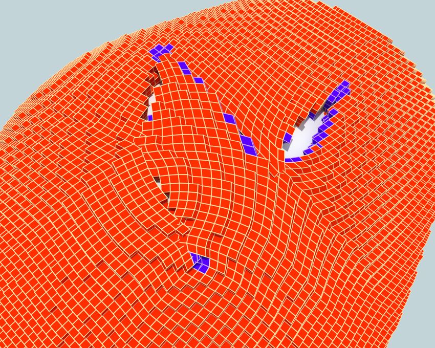
Figure 2: Top: Simulation of Z-Plasty, a basic maneuver resulting in anisotropic scaling along two perpendicular directions.
Z-Plasty is a common building block leveraged in more elaborate repairs. Bottom: Rhomboid flap procedure for closing a
quadrilateral aperture of excised tissue on the scalp. The embedded simulation grids are shown on the right.

Surgical skills targeted by computer-based training solutions     rounding tissues. In plastic surgery, cognitive training ad-
have been classified [Gallagher et al. 2005] in two major cat-    dresses the mental challenge of how these elemental surgi-
egories. Psychomotor skills refer to the dexterous use of the     cal puzzle-pieces are sequenced and adapted to craft a com-
surgeon’s hands to manipulate instruments in the course of        plex operation. Unfortunately, 3D computer-based cognitive
an operation. In plastic surgery, psychomotor training in-        training solutions for facial reconstructive surgery are virtu-
volves mechanical aspects of surgical tasks, such as the “feel”   ally nonexistent; common educational materials are limited
of tissue being cut or the nuances of manipulating a scalpel      to 2D sketches and still photographs of procedures.
to enact a curved incision. For example, training for laparo-
scopic procedures requires a clinician to be familiar with the    We present an interactive virtual surgery simulation frame-
tactile response of pushing and pulling on organs and to          work using lattice-based embedded discretizations of elastic
practice coordination skills required for suturing and cau-       tissue, which can be used to author plastic surgery proce-
terization. A number of computer-based solutions focus on         dures and serve as a cognitive training tool for novice sur-
psychomotor training [Mendoza and Laugier 2003; De et al.         geons. Our system integrates a number of mature discretiza-
2005; Kim et al. 2007; Lindblad and Turkiyyah 2007]. In           tion and numerical solution techniques with new data struc-
contrast to psychomotor training, cognitive skills and train-     tures, aggressive parallelization practices and a remote deliv-
ing are largely mental rather than dexterous exercises. For       ery mechanism for computation, in order to improve fidelity,
example, in the procedure shown in Figure 1, the surgeon          interactivity and ease-of-use. Although we focus on surgical
needs to contemplate how to best repair a large square skin       simulation, we believe the utility of our methods transcends
defect (i.e. area of excised tissue) by making auxiliary inci-    the scope of this clinical application and can be leveraged in
sions that create properly shaped “puzzle pieces” which can       broader scenarios of interactive simulation.
be sutured together without creating excessive stress. Chen-
                                                                  Our key technical contributions include:
tanez et al. [2009] described a cognitive training system for
steerable needle insertion, where the mental challenge lies in      • A geometric data structure that hybridizes a grid-based
planning a sequence of actions involving needle flexion and           discretization with an explicit hexahedral mesh in order
torsion, in order to achieve a desired insertion trajectory.          to resolve non-manifold topological features, such as
                                                                      narrow incisions, while preserving as much regularity
Cognitive training is paramount in plastic surgery and ac-            and parallel potential of uniform grids as possible.
quired through many years of practical experience. Most
reconstructive procedures are not envisioned or taught as           • An object-oriented programming paradigm via which
monolithic operations; instead, they are composed as a se-            Cartesian grid-based embedded discretizations of elas-
quence of fundamental building blocks. Graphics practition-           tic models can be systematically mapped on a spectrum
ers would associate these elementary actions with geometric           of multithreaded and SIMD-oriented platforms. This is
transforms: shear, rotation, uniform or anisotropic scaling.          demonstrated on both the x86 SSE/AVX instruction
Of course, applying such transformation on live tissue is very        set, as well as on the Intel Xeon Phi platform.
different than their application on a geometric model. When         • A tiered deployment strategy where the interactive
stretching a tissue patch in one direction to 125% of its orig-       front-end is mapped to a lightweight client device, ge-
inal length while contracting it in the transverse direction          ometrical modeling is handled by a remote server, and
down to 80%, squeezing-and-stretching in-place is typically           numerical solver by a many-core accelerator.
not the desired way to execute this transform. Real skin
might not stretch that far or buckle in the transverse di-        In addition to the technical merit of our methodology, we
rection during the process. A maneuver called the Z-plasty        hope that our work serves to improve awareness of a highly
(see Figure 2, top) achieves the same net effect, with a more     rewarding emerging application which can greatly benefit
graceful stress distribution and a smooth blend to the sur-       from innovations in graphics and visual computing.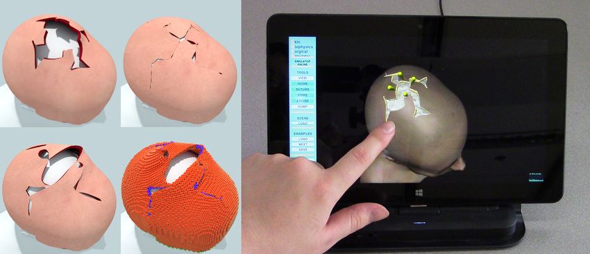
2    Related Work                                                   sons of simplicity and performance. Mueller et al. [2004]
                                                                    employed an embedding scheme to perform volumetric sim-
Computer graphics research has produced several diverse             ulation of objects described by their boundary mesh. The
techniques for model deformation. Procedural techniques             regularity of lattice embeddings has also been exploited
[Joshi et al. 2007; Wang and Phillips 2002; Kavan et al. 2008]      in shape matching techniques [Rivers and James 2007] to
offer real-time performance for certain animation tasks but         achieve significant performance accelerations. Embedding
lack the physical accuracy needed in surgical simulations.          has been combined with homogenization [Nesme et al. 2006;
Consequently, some research ventures into surgical simula-          Kharevych et al. 2009] to resolve sub-element variation of
tion turned to elastic deformation models [Terzopoulos et al.       material parameters, optionally with the use of non-manifold
1987] that responded more realistically to scenarios of prob-       embedding lattices to support objects with a branching
ing and cutting [Bro-nielsen and Cotin 1996; Mendoza and            structure [Nesme et al. 2009]. Jerabkova et al. [2010] em-
Laugier 2003; Nienhuys and van der Stappen 2001]. How-              ployed a method similar to our own, using a finer voxel grid
ever, these early works were limited in their scope and ef-         to capture material topology to be embedded in a coarser,
fectiveness due to computational cost, geometric constraints        non-manifold voxel grid. Finally, Zhao and Barbič [2013]
and oversimplified material models. In this section we out-         demonstrated the use of multiple voxel grid domains to seg-
line prior contributions that help address these limitations,       ment a model hierarchically, which they used to simulate
and review a number of existing surgical simulation systems.        plants at interactive rates. Extended FEM (XFEM) formu-
                                                                    lations have also been explored [Jeřábková and Kuhlen 2009],
Virtual materials and anatomy modeling Approaches                   where discontinuities are introduced into the element’s shape
based on the Finite Element Method (FEM) have been par-             functions, to model cutting. In a similar vein, Kaufmann et
ticularly popular in the medical simulation community [Mar-         al. [2009] used discontinuous Galerkin FEM formulations.
chal et al. 2008] where the need for biologically accurate ma-      Others have dispensed with mesh based discretizations com-
terials is more pronounced. In one of the earliest uses of ad-      pletely, preferring meshless methods [De and Bathe 2000]
vanced materials in computer animation, Chen and Zeltzer            which were also used for surgical simulation [De et al. 2005].
[1992] focused on anatomical structures such as muscles.
FEM techniques were further leveraged in the animation              Surgery simulation While much of the previously dis-
literature for the discretization of linear elasticity for frac-    cussed work is geared towards general elastic body simula-
ture modeling in a small-strain regime [O’Brien and Hodgins         tion in computer graphics, many relevant results originated
1999]. Highly nonlinear materials such as active musculature        in surgery-specific work. Pieper et al. [1995] demonstrated a
[Teran et al. 2003] exposed challenges in robustness and nu-        very early surgical simulation platform for facial procedures,
merical stability of FEM discretizations. Invertible FEM            using FEM elastic shells. Many surgical simulation projects
[Irving et al. 2004] improved simulation robustness in sce-         focus on the mechanical manipulation of organs and other
narios involving extreme compression, while modified New-           soft internal objects [Nienhuys and van der Stappen 2001;
ton methods [Teran et al. 2005a] reduced the cost of implicit       Kim et al. 2007]. Even expensive commercial simulators like
schemes with large time steps. Several of these algorithms          the Lap Mentor and GI Mentor primarily focus on push-
have been incorporated in open-source modeling and simula-          ing and cutting simulated internal organs [Simbionix USA
tion packages [Sin et al. 2013]. Solutions have also been pro-      Corporation 2002–2014b; Simbionix USA Corporation 2002–
posed for material behaviors such as incompressibility [Irving      2014a]. These types of simulations are so common that sev-
et al. 2007] and viscoelasticity [Goktekin et al. 2004; Woj-        eral open source frameworks have been built to specifically
tan and Turk 2008], both of which can be found in typical           support further development [Allard et al. 2007; Cavusoglu
biomaterials. Recent results in coupled Lagrangian-Eulerian         et al. 2006]. These provide easy access to common com-
simulation of solids have also facilitated the inclusion of in-     ponents like haptic feedback and APIs to connect multiple
tricate contact and collision handling in biomechanical mod-        simulated components. Certain surgical simulation systems
eling tasks [Sueda et al. 2008; Li et al. 2013; Fan et al. 2014].   are tailored to specific skills, including interactive simula-
Simulation of topology change A number of techniques                tions of needle insertion [Chentanez et al. 2009].
have targetted topology change during simulation, due to
cutting or fracture. Early work [Terzopoulos and Fleischer          Performance optimizations Improving simulation rates
1988] resorted to breaking connectivity of elements when            is a common challenge for many interactive modeling tasks,
stress limits were exceeded. Later methods [Nienhuys and            and even more so for accuracy-conscious applications such
van der Stappen 2001] split tetrahedra near cut boundaries          as virtual surgery. Attempts to improve performance have
and then used vertex snapping to more accurately approxi-           either relied on new data structures, faster solvers, or aggres-
mate the cut. Local remeshing was also employed to simu-            sive use of parallelization. The Boundary Element Method
late cracks in brittle materials [O’Brien and Hodgins 1999].        [James and Pai 1999] has been used to achieve interactive
An issue with such subdivision schemes is the possible cre-         deformation rates for objects manipulated via their surface.
ation of poorly conditioned elements, which prompted a              Hermann et al. [2009] analyzed data flow in their simula-
number of authors to pursue embedded simulation schemes             tions to inform a parallel scheduler for multicore systems.
[Molino et al. 2004; Teran et al. 2005b]. These techniques          To avoid write hazards during parallel code execution, Kim
use non-conforming meshes with elements which are only              et al. [2011] proposed a system of computation phases with
partially covered by material, in lieu of conforming remesh-        coalesced memory writes, which allowed them to parallelize
ing. Embedded simulation can provide a great degree of flex-        force computation. Related efforts by Courtecuisse and Al-
ibility in cutting and fracture scenarios [Sifakis et al. 2007],    lard [2009], developed a parallel version of the Gauss-Seidel
although cutting meshes along arbitrary surfaces requires           algorithm that can run on GPUs. Regular discretizations
delicate book-keeping and careful handling of degeneracies.         have also been coupled with multigrid solvers to facilitate
                                                                    GPU accelerations for elastic skinning techniques [McAdams
Embedded simulation The use of non-conforming meshes                et al. 2010]. However, in spite of the efficiency of multigrid
has valuable benefits for fracture modeling, but embedded           schemes, adapting them to the presence of incisions or other
techniques have also been used in their own right for rea-          intricate topological features can be a nontrivial proposition.
3     Project scope and design decisions
Our target application carries a unique set of requirements
related to accuracy, usability and effectiveness. We sought
to produce a robust and usable prototype, appropriate for
a pilot deployment (Figure 3). As a consequence, our de-
sign goals represent a balance between facilitating future
extensions and leveraging all opportunities for optimizing
performance and interactivity now. This section discusses
the factors influencing our design decisions, including both
long-term principles and short-term opportunities.

3.1   Clinical scope

In the current iteration of our framework, we focused on
the virtual simulation of local flaps, as well as anatomical
flaps on the human cranium. Local flaps are surgical de-           Figure 3: Pilot deployment of our interactive web-based
signs defined on a flat tissue layer with uniform thickness,       simulator with 14 Plastic & Reconstructive Surgery medical
which is not attached to underlying bone or cartilage (Fig-        residents at the University of Wisconsin-Madison.
ure 2, top). Cranial flaps (Figure 2, bottom) are somewhat
similar in that the tissue has relatively uniform thickness        feasible or not. As a consequence, our framework is designed
(of a few millimeters) and is not attached to the underlying       to accommodate heterogeneous hyperelastic materials, with
bone. Of course, cranial flaps are not flat, and similar inci-     no explicit provisions at this point for plasticity or viscoelas-
sion shapes can produce different end results, depending on        ticity. Anisotropy is a much more pertinent trait; even on
the curvature of the cranium. Procedures on the cranium            the cranium, the bottom of the scalp is lined with a thin fi-
are a significant (and nontrivial) part of the clinical curricu-   brous sheet that is a significant source of material anisotropy
lum in a plastic surgery residency program.                        (in-plane stiffness vs. normal to the scalp surface). Our de-
Geometry of repairs Due to the small, uniform thickness            sign choice was to outfit our algorithmic framework with
of tissue in local and cranial flaps, incisions can be designed    full support for heterogeneity and substantial support for
purely as curves on the skin surface, with the assumption          anisotropy, including active anisotropic behaviors such as
that any incision will proceed through the entire thickness of     contractile muscle fibers. However, our interactive surgical
the tissue (perpendicular to the surface). This specific scope     examples were carried out with isotropic materials exclu-
greatly simplifies user interface, as cuts can be drawn on the     sively, and our support for anisotropy and active muscle ele-
tissue surface. In contrast, surgical procedures on anatom-        ments is only leveraged to offline musculoskeletal simulations
ical parts with greater volumetric extent would necessitate        within our framework (see Section 7).
complex input devices to prescribe 3D incision paths.              Dynamics As a cognitive training platform, our frame-
Contact scenarios Surgical repairs on the cranium cer-             work’s main priority is to capture the stationary shape that
tainly depend on proper contact between the elastic tissue         a given repair results in. As a consequence, an implicit or
and the underlying bone, but do not strictly require static        even quasistatic time evolution scheme is very well toler-
contact between different tissue parts, as all incisions are       ated for our application, and aligns well with the interac-
thoroughly sutured after manipulation (not the case for op-        tivity requirements of our platform. The cost paid for this
erations in other parts of the body). Accordingly, our system      compromise is that transient deformation states during high-
only performs collisions between tissue and bone, forgoing         velocity maneuvers are not dynamically accurate, but merely
expensive self-collision processing. We designed our system        iterations towards the solution of the implicit/quasistatic
to be extensible to self-collision handling, but optimized our     evolution scheme used.
current deployment with the knowledge that only collisions         Solvers, scalability and parallelization A number of au-
with external bodies are needed at this juncture.                  thors have been successful in leveraging multigrid schemes
Timeline of incisions A large majority of surgical repairs         [Dick et al. 2011; McAdams et al. 2011] in the simulation
on the cranium can be designed with all incisions made at          of elastic solids. For our specific application, the geometry
once, in the beginning of the procedure. This allows us to         of the computational domain (thin volumetric tissue sheets)
improve the efficiency and robustness of incision modeling         would complicate the design of multigrid transfer operators,
dramatically, applying all topological change at a single in-      while future extensions to highly anisotropic and hetero-
stance in time. This is certainly not the case for other proce-    geneous materials would require nontrivial adaptations to
dures (e.g. cleft lip and palate repair or other procedures on     a performance-tuned multigrid scheme. Thus, we avoided
the lower face) where incisions have to be applied in distinct     committing to a multigrid solver at this point, and relied
time instances, while tissue is actively manipulated.              on iterative solvers such as Conjugate Gradients. That be-
                                                                   ing said, we could not afford to forego parallelism and vec-
3.2   Physics-based modeling                                       torization, as the performance benefit over a scalar single-
                                                                   threaded implementation would be dramatic. In light of this,
Material properties of tissue Human tissue is a complex            we adopted a Cartesian-grid based embedded discretization
heterogeneous nonlinear material, with anisotropic, elasto-        that favors parallel accelerations while (i) designing a hybrid
plastic and viscoelastic traits. Nevertheless, although plas-      embedded structure that reconciles lattice embeddings with
ticity and viscoelasticity are important postoperative fac-        non-manifold topology near incisions and (ii) implementing
tors, our domain collaborators have suggested that these be-       a programming paradigm to systematically generate multi-
haviors are of secondary importance within a surgical time-        threaded and vectorized versions of our algorithmic kernels
frame in determining whether a given repair is mechanically        as material properties might be adapted and refined.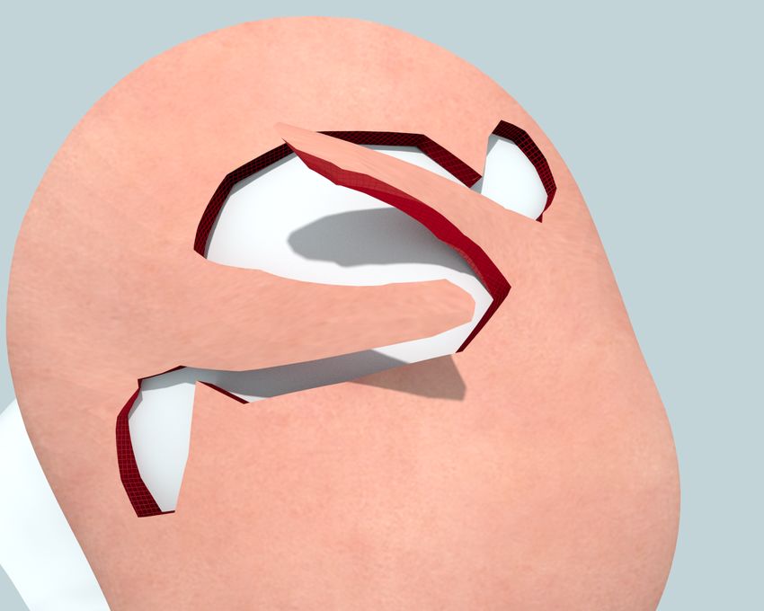
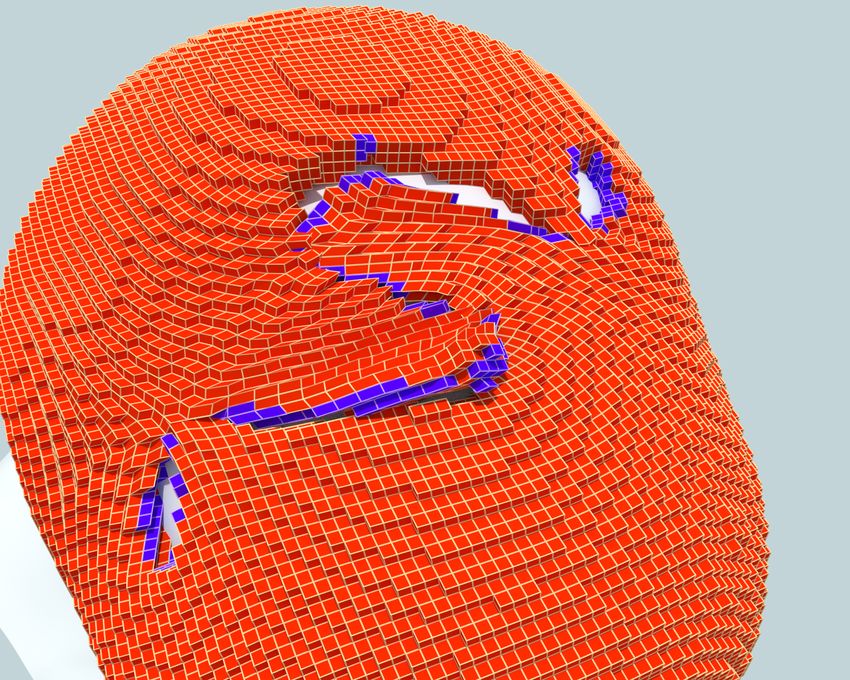
Figure 4: Dual S-Plasty procedure on the scalp; a large oval-shape defect is patched by transposing two S-shaped flaps.

3.3    User experience and ease of deployment                     ery configuration of constraints or kinematically prescribed
                                                                  degrees of freedom, we seek to solve for the nodal displace-
It is essential for the continued evolution of our framework to   ments x such that the force equilibrium equation f (x) = 0
establish a communication channel between computer graph-         is satisfied. At each iteration k we aim to refine our solution
ics developers and clinical end-users. Thus, we place great       for x(k) by seeking a correction term dx such that:
emphasis on a system that can be deployed to our domain                                                              df
testers quickly and inexpensively, provides a versatile up-                0 = f (x(k) + dx) ≈ f (x(k) ) +                       dx ⇒
grade path, and is intuitive and enjoyable to use as to elicit                                                       dx   x(k)

continued interest from our clinical collaborators.
Simple interface We aim to provide a simple, yet expres-                                     df
                                                                                        −                    dx = f (x(k) )             (1)
sive and intuitive interface to clinical users of our system.                                dx   x(k)
Our current solution is centered around three basic interface                       |        {z          }
                                                                                              K
“tools”: (a) The incision tool is a drawing interface by which
cuts are sketched as spline curves on the tissue surface. (b)     Equation 1 highlights the two terms we must be able to pro-
The hook tool establishes soft spring-based constraints be-       vide for each force component within our system, including
tween a point on the visible surface of the tissue and a user-    elastic and contact forces. The right hand side is the total
movable point in space. (c) The suture tool enacts a suture       force as a function of the current position. If we had em-
between two points on the tissue surface. The attachment          ployed a direct method, the left hand side could have been
                                                                                                                             df
is enforced as a stiff zero-length spring.                        represented by extracting the tangent stiffness matrix dx     .
Remote deployment In order to improve simulation per-             However, our iterative Krylov solver only requires an algo-
formance, we aggressively use parallel-optimized solvers on       rithmic routine for computing products of the form Kw. We
multicore systems (our platform uses an SMP server, with          transform our problem into one of this form by using the no-
Intel Xeon Phi accelerators). It is, however, impractical to      tion of a differential. Interpreting w as a nodal displacement
deploy such a server at the location of our end-users (who        δx, we rewrite the left hand side of equation 1 as:
are surgical residents in teaching hospitals), and even more
challenging to push algorithmic upgrades as our framework                               df
                                                                                  −                 δx := −δf [δx; x(k) ]               (2)
evolves. We have thus separated the graphical front-end                                 dx   x(k)
into a lightweight application that runs on web-based clients
(Figure 3), while the burden of numerical simulation is of-       The left hand side is now in a form equivalent to Kw, suit-
floaded to a simulation server. This is possible as the front-    able for use in our iterative solver. The following sections
end only needs to dispatch user manipulations (movements          detail how forces f (x(k) ) and force differentials δf [δx; x(k) ]
of hooks, placement of sutures) to the host simulator, and        are computed for every different force type in our method.
only receive surface geometry updates from the simulation
server even if volumetric simulation is taking place.             4.1   Elastic Forces

                                                                  Isotropic elasticity Our system models the underlying me-
4     Elasticity discretization                                   chanical behavior of soft tissue with an isotropic substrate,
                                                                  which is optionally augmented with additional anisotropic
We start by describing our discretization of elastic forces       force contributions (either from passive fibrous structures, or
and the time evolution scheme used in our methodology.            active musculature). For the discretization of the isotropic
We discretize the equations of elasticity on a regular Carte-     component we derive forces and force differentials using
sian lattice, on which the simulated material is embedded.        FEM with trilinear shape functions and a one-point quadra-
Although we actually allow our grids to contain duplicate         ture [McAdams et al. 2011; Patterson et al. 2012; Sifakis and
cells and non-manifold features, as we detail in Section 5,       Barbic 2012]. The exact process for forces and differentials
each individual cell is a regular cube element, as in previ-      is reiterated in Algorithm 1. We note the existence of two
ously published lattice-based discretizations [McAdams et al.     user-defined functions in the pseudocode:
2011; Patterson et al. 2012]. We review the relevant theory
with a focus on exposing regular algorithmic kernels, which       DiagMatrix P_Hat(DiagMatrix Sigma, Params p)
we feed into a stream processing pipeline in Section 6.           Vector dPdF_Hat(DiagMatrix Sigma, Params p)
Quasistatic evolution As we are primarily concerned with          By providing a custom implementation of the above two
the equilibrium shapes resulting from user manipulation and       functions, we can implement any isotropic material model
flesh/bone collision, we implement a quasistatic evolution        without modifying any other part of the force computation
based on a Newton-Raphson solver with Conjugate Gradi-            pipeline. This is a flexibility that we strive to retain, to sup-
ents used to solve the linearized system at each step. For ev-    port more complex biomaterials in the future. Note that the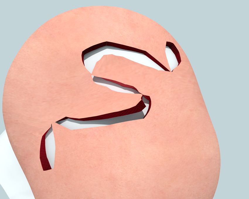
Algorithm 1 Procedures for computing elastic force and force differentials. Sections highlighted in gray indicate values which
can be precomputed at the start of each Newton-Raphson iteration. The functions P_Hat and dPdF_Hat can be user-defined
to implement arbitrary isotropic materials. The reshape operation concatenates eight nodal vectors in a cell (positions,
displacements, forces, etc) into a 3 × 8 matrix and vice versa. G is a 3 × 8 gradient matrix, as defined in [McAdams et al.
2011]. V0 = h3 is the volume of the cartesian cell. T is a sparse 4th order tensor as defined in [Teran et al. 2005a]
                                                                 1: procedure δFElastic(x,δx, params p)
 1: procedure FElastic(x, params p)
                                                                 2:    reshape x → Ds , δx → δDs
 2:    reshape x → Ds
                             T                                   3:    compute F ← Ds GT , δF ← δDs GT
 3:    compute F ← Ds G
                                                                 4:    compute [U, Σ, V ] ← SVD(F)
 4:    compute [U, Σ, V ] ← SVD(F)
                                                                 5:    compute T ← dPdF_hat(Σ, p)
 5:    compute P̂ ← P_hat(Σ, p)                  P(F)
                              T                                  6:    compute δF  ˆ ← UT δFV
 6:    compute P ← UP̂V                                                                                            δP(F, δF)
                                                                 7:    compute δP  ˆ ← T : δFˆ
 7:    set H ← V0 PG
                                                                 8:    compute δP ← UδPV    ˆ T
 8:    reshape H → f
                                                                 9:    set δH ← V0 δPG
                                                                10:    reshape δH → δf

                                                                                    (j)
second function returns a sparse 3×3×3×3 tensor, which has       In the first case, pi represents a embedded spring endpoint
21 nonzero entries out of which only 12 are unique (reflected    where W is a 3 × 24 weight matrix and x are the positions
in the return type), as defined by Teran et al. [2005a]. Con-    of the vertices from the embedding cell. The second case
crete formulas for the above functions have been previously                                                (j)
                                                                 refers to a non-embedded target, where pi is simply a con-
given [Patterson et al. 2012] for Corotated, Neohookean and      stant position in space. Hook constraints use one embedded
Mooney-Rivlin isotropic materials.                               and one fixed endpoint, while suture constraints have both
Anisotropy Our framework supports adding an anisotropic          endpoints embedded. In either case, forces and differentials
response on top of the base isotropic substrate. We allow        are directly computed by differentiating the spring energy as
custom anisotropic material definitions by accepting an al-      fspring = −∂Espring /∂x, δfspring = −∂ 2 Espring /∂x2 : δx.
ternative implementation of the Piola Stress P(F) and its
                                                                 Collisions with kinematic bodies are handled using the
differential δP(F;δF). Since our surgical examples do not
                                                                 “hook” infrastructure; a number of collision proxies are
currently make use of this capability, we defer to the supple-
                                                                 seeded on the model surface, and when collision is detected
mental document for details on how the muscle constitutive
                                                                 their stiffness is set to a nonzero value, while their target end-
model of Teran et al [2003] can be cast in these terms. An
                                                                 point is set to the projection on the surface of the colliding
offline musculoskeletal simulation using this feature is dis-
                                                                 body. The suture infrastructure can be used to support self-
cussed in Section 7.
                                                                 collisions, following the paradigm of McAdams et al. [2011].
Stabilization For performance, our discretization method         The only difference is that, for sutures, the embedding of
uses a single point quadrature scheme, which requires only       both spring endpoints is known at the moment the suture
one Singular Value Decomposition per cell as opposed to          is introduced. For self collisions, the embedding coordinates
a more traditional Gauss quadrature which requires eight.        of one endpoint for every “self-collision spring” can be de-
As detailed in McAdams et al [2011], left uncorrected, this      termined dynamically by the collision detection phase.
approach produces hourglass instabilities due to particular
deformation modes which do not affect the discrete energy,
and we employ their stabilization corrections to account for
                                                                 5    A hybrid embedding lattice structure
this issue. If additional accuracy is desired, a four point
quadrature scheme proposed in Patterson et al [2012] could       We employ an embedded simulation similar to other au-
easily be substituted, at an additional computation cost.        thors, who used regular lattice embeddings for performance
                                                                 [Müller et al. 2004; Rivers and James 2007; McAdams et al.
4.2   Interaction Forces                                         2011]. However, due to the presence of extremely thin in-
                                                                 cisions in our surgical models, standard lattice embedding
In addition to internal elastic forces, our system supports      would not be able to resolve the tissue topology, unless an
interaction forces related to both user interaction and col-     extremely high resolution embedding was used. We thus
lision with kinematic objects. User interaction consists of      adopt a non-manifold lattice-derived embedding discretiza-
manipulation hooks, which are spring attachments of mod-         tion in the spirit of Virtual Node or XFEM methods [Molino
erate stiffness between a tissue surface location and a user-    et al. 2004; Sifakis et al. 2007; Nesme et al. 2009]. Although
controlled point in space, as well as sutures which are sig-     the use of non-manifold embedding meshes recovers much
nificantly more stiff springs attaching two locations on the     of the topological expressive ability of conforming meshes, it
tissue surface. Both of these forces result in augmentation      jeopardizes one of the most attractive features of regular em-
of the internal elastic energy by spring terms of the form:      bedding lattices, the fact that connectivity is implicit in the
                                                                 lattice structure as opposed to explicitly stored in a mesh.
                            X ki   (1)      (2)                  The performance impact of implicitly defined topology can
               Espring =       ||p − pi ||22
                             2 i                                 be profound; the memory footprint of explicitly stored con-
where ki is the spring constant and the endpoints can take       nectivity information can easily exceed the state variables
one of two forms:                                                themselves (e.g. vertex positions) and reduce effective mem-
                                                                 ory bandwidth by necessitating indirect memory access. In
               (j)                  (j)
              pi     = Wx     or   pi     = const                our work, we strive to leverage the best of both worlds: We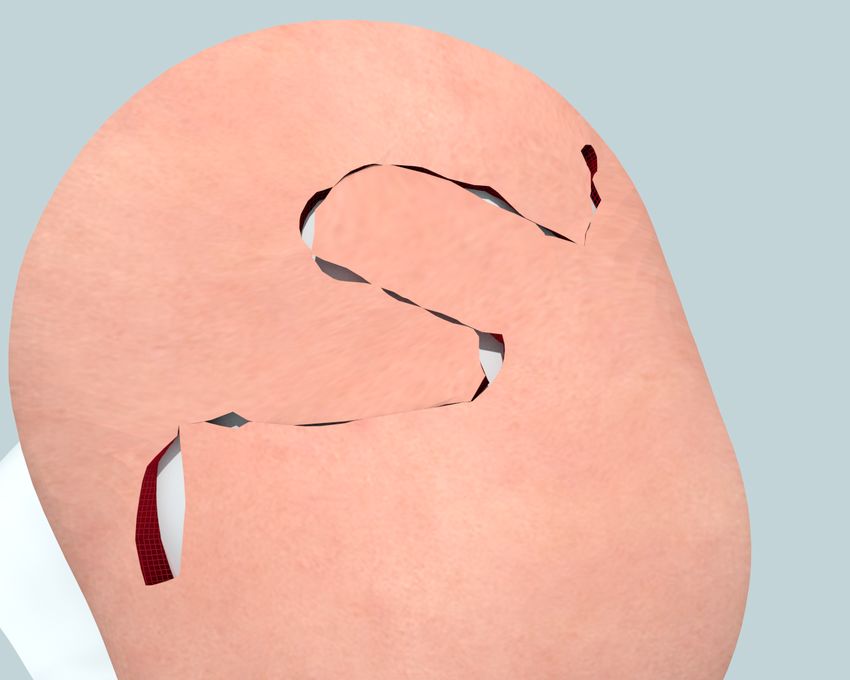
Figure 5: Illustration of a cut generating a hybrid lattice. (a) A cut passing through the grid. (b) Mesh cells generated for the
top half of the cut. (c) Mesh cells generated for the bottom half of the cut. (d) Cut surface is colored to show cell assignment.

use an (implicit topology) Cartesian grid to capture the ma-       ding or numerical solution details from the visual front-end.
jority of the embedded model in regions where non-manifold
duplication is not needed. We retain the topological flexibil-     5.3   Non-Manifold mesh generation
ity of non-manifold embedding lattices by hybridizing this
grid with an (explicit topology) hexahedral mesh used to
                                                                   We now seek to construct a coarser resolution explicit mesh
describe regions in the vicinity of narrow slits and incisions.
                                                                   discretization, which is allowed to be non-manifold in re-
                                                                   gions, as shown in Figure 5. We will extend the paradigm
5.1   Surface Model                                                of non-manifold embedding proposed by Teran et al. [2005b]
                                                                   and Sifakis et al. [2007] using the precomputed fine grid ras-
Prior to elasticity discretization, a watertight surface model     terization to answer material connectivity predicates. Our
of the flesh, including any incisions, must be created. In our     non-manifold mesh generation process is outlined in Algo-
system, incisions are generated from user specified line seg-      rithm 2, and illustrated intuitively in Figure 5. Note that, in
ment curves, which guide constructive solid geometry (CSG)         the pseudocode provided, there are two geometric predicates
difference operations to produce cut surface meshes. We be-        being used: (a) Determination of material components (line
gin from a user specified line segment curve from which we         3) requires the identification of all disconnected components
construct prisms by thickening the line segments tangentially      of material present in the intersection of our domain with a
and perpendicularly along the surface normal. We then ap-          given lattice cell. (b) Adjacent-element material continuity
ply these prisms in a subtraction operation with the surface,      (line 10) is a predicate invoked to determine if two material
resulting in a slightly thickened incision (Figure 6). Discon-     fragments, associated with adjacent lattice cells, exhibit ma-
nected regions produced during this step can be marked and         terial continuity across their common face. These two geo-
removed by the user. Note that for scenarios involving ma-         metric predicates are expressed in a fashion that is agnostic
lignant tissue, discarding of excised tissue is commonplace.       to the underlying geometric representation of material; in
                                                                   Teran et al. [2005b] the assumption is that a tetrahedralized
5.2   Rasterization                                                model of the material is available, while Sifakis et al. [2007]
                                                                   define material fragments indirectly, by specifying cutting
Given a cut surface mesh, we first create a fine rasteriza-        surfaces instead. In our case, the availability of the fine-grid
tion of the surface. The resolution of the rasterization is        rasterization makes both such operations purely combinato-
selected to capture all desired topological detail (typically      rial in nature. Material fragments within a coarse cell are
an order of magnitude finer than simulation resolution). In        computed via flood-fill, and fragments on adjacent cells are
Figure 7, it is possible to see the fine rasterization grid in     continuous if they contain adjacent fine cells on their ras-
contrast to the coarser simulation resolution. The raster-         terization. At the conclusion of this step, we have produced
ization is performed by detecting all voxels intersected by        a coarse mesh (with explicitly stored connectivity), whose
the object surface and flood-filling to mark the volumetric        topology is as close as possible to the embedded geometry.
material region. Once the rasterization is complete, subse-
quent embedding operations are purely combinatorial, and
not sensitive to poor conditioning of surface mesh elements.
Additionally, this fine-grid embedding can also act as an in-
terface layer to more complex embedding schemes, such as
the non-manifold approach described next. We leverage this
by translating any deformation results back to the fine-grid
embedding prior to rendering, to hide non-manifold embed-

Figure 6: Incisions in the flesh surface model are created         Figure 7: Fine grid rasterization of a cut. Fine cells within
by extruding and thickening user specified line segments.          the cut are empty, and colored to show material continuity.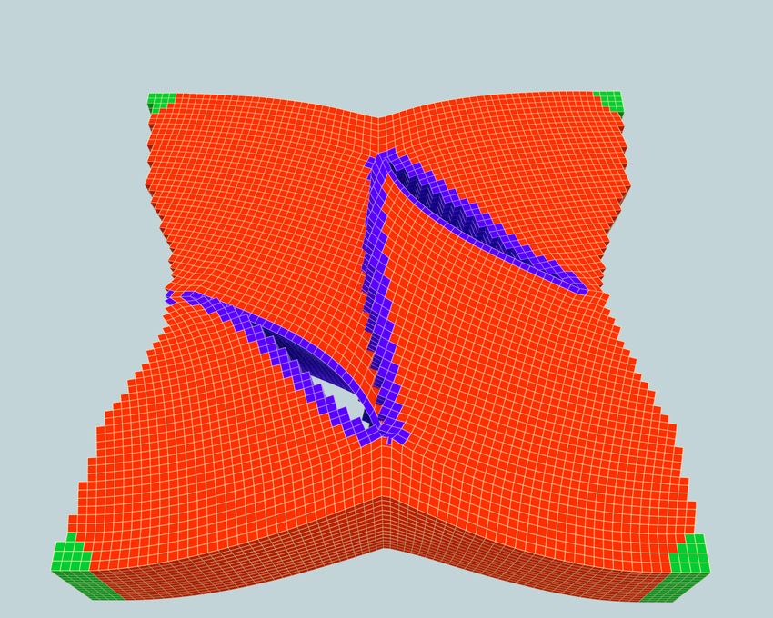
Algorithm 2 Algorithm to Construct Non-Manifold Mesh             It should be noted that this set of rules is not strictly optimal
Input: Coarse Resolution                                         in the sense of mapping the most elements into the grid. A
 1: function Generate_Nonmanifold_Mesh                           more aggressive strategy would be to select one element from
 2:    for all Coarse Cells: i do                                each set of geometrically co-located items and map it to the
 3:       C ← Determine_Material_Components(i)                   grid. We defer investigation of similar compaction heuristics
 4:       for all Components in C do                             to future work. Note: In all our surgical examples (Figures
 5:           Instance separate copy of i                        1,2 and 4) mesh-mapped embedding cells are indicated with
 6:           Generate unique, separate DOFs                     blue color, grid-mapped ones in red.Typically, only a minor-
 7:           Assign descriptor of material content              ity of cells is mesh-mapped, allowing us to retain the bulk of
                                                                 performance benefits of implicit grid-mapped embeddings.
 8:    for all Geometrically adjacent cell pairs: (i, j) do
 9:       for all Pairs of duplicates from i and j: (h, k) do
10:           if Material_Is_Continuous(h, k) then               6     Software engineering and deployment
11:              Mark shared vertices as equivalent
12:    for all Coarse Cells: i do                                6.1   Parallelization
13:       Compare all duplicates of i
14:       Collapse duplicates with equivalent DOF’s              Our framework relies on both multithreading and vectoriza-
Output: An explicit, possibly non-manifold mesh                  tion (SIMD) to obtain the best possible performance. The
                                                                 fact that our Cartesian-based discretization consists of iden-
                                                                 tically shaped elements offers a great opportunity to leverage
                                                                 both thread-level and data-level parallelism, due to the in-
5.4   Reduction and Remapping                                    herent regularity of the simulation kernels.
For the final step in hybrid lattice construction, we attempt    Blocking As described in Section 4 on discretization, forces
to map as much of the explicit-connectivity mesh as possible     are computed on a per cell basis. A naive multithreaded
back onto an implicit-connectivity grid to recover regularity.   port would result in write hazards at nodal positions, un-
From the explicit mesh, we have two geometric primitives to      less expensive synchronization was used. Simple partition-
consider for remapping: nodes and cells. For simplicity, we      ing would eliminate this issue, but would not make efficient
will first consider nodes and then cells. Figure 8 illustrates   use of modern SIMD-enabled processors. Instead, we employ
the results of the remapping rules below:                        a blocking scheme to avoid write hazards while retaining a
   • Nodes are mapped to the grid if and only if they possess    memory layout favorable for vectorization. Our objective
      no duplicates.                                             is to redefine our “quantum” of computation from a single
                                                                 lattice cell, to a geometric neighborhood (or block) that is
   • Cells are mapped to the grid if and only if all of their    processed concurrently using vector operations. We adopt a
      vertices have been mapped to the grid.                     block size of eight cells arranged as a 2 × 2 × 2 cube. This
Each mesh cell remaining in the hybrid lattice is associated     formation allows us to fit blocks into eight-wide vectors and
with a coordinate from the grid. This mapping will become        later we will demonstrate how we can adapt to larger and
important later when we discuss the block-based acceleration     smaller vector widths. In this way, each cell in the block can
structures. After these rules are applied, the new structure     be considered a “channel” in the vector. Blocks are tiled to-
must adhere to several post-conditions.                          gether to cover the extent of the lattice. However, restricting
   • All grid cells are composed only of grid nodes.             the contents of a non-manifold hybrid lattice to the spatial
   • Mesh cells contain one or more mesh nodes.
                                                                 (a)                           (b)

                                                                 (c)

           (a)                               (b)
Figure 8: From an explicit mesh (top), we generate (a)           Figure 9: Generating Blocks. (a) Block boundaries super-
mesh mapped nodes in red, grid mapped nodes in black and         imposed over hybrid lattice. (b) Non-manifold contents of
(b) mesh mapped cells in red, grid mapped cells in gray.         each block region. (c) Final manifold blocks for each region.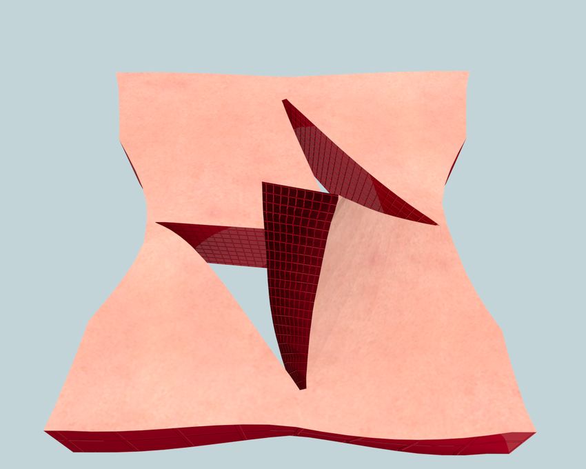
extent of a single block could easily yield more than one cell    semantics of fundamental data types are very similar across
at each position in the block, as illustrated in Figure 9. To     scalar/vector platforms, even if the interface differs. Our
create blocks without overlapping cells, we employ a greedy       system is rooted on two templatized C++ classes:
algorithm which collects cells into manifold groupings along
block boundaries, as seen in (Figure 9c). The full algorithm      template class Number;
for this process is described in Algorithm 3.                     template class Mask;

We use the partitioning of our lattice into blocks to cir-        Class Number is an abstraction of a single floating point
cumvent write dependencies during multithreaded execu-            number in a scalar platform (scalar_arch==float) or of
tion. Prior to the execution of any kernel involving force        a 4/8/16-wide vector register in SSE/AVX/Xeon Phi plat-
computation, we copy the state variables from either the grid     forms (scalar_arch:=__mm128|__mm256|__mm512). Simi-
or mesh structures that natively store them, into duplicate       larly, class Mask is an abstraction of the result of a com-
copies for every block. We label this process a Compaction        parison operation, in a form that can be used to per-
step, which is essentially a gather operation that yields a       form a conditional assignment; thus Mask encapsu-
representation of the state variables into a flattened array      lates a single C++ boolean variable, Mask cap-
of blocks (with shared variables duplicated across blocks).       tures a 256-bit mask usable in AVX BLEND instructions, while
Subsequently, force computation can be executed in parallel       Mask encapsulates the special concept in Intel
on each block, without write dependencies, by allowing each       Xeon Phi of a 16-bit mask register that is used in compar-
block to record its own force contribution to the lattice nodes   isons and conditional assignments. We provide enough over-
it touches. The reverse operation, labeled Uncompaction           loaded operators in the interface of these classes to allow
scatters and accumulates the contents of the per-block forces     them to be used in algebraic expressions regardless of the
back to their native (non-duplicated) grid or mesh storage.       encapsulating vector width. Ultimately we use them to con-
Write dependencies can be avoided at this stage by partition-     struct macroscopic kernels of the form:
ing this parallel operation on the grid or mesh variables that
collect the per-block contributions. As a result, complex         template
force computations can fully enjoy the benefits of thread-        void Add_Force_Differential(
and SIMD-parallelism, without being concerned with data               const T_DATA (&dx)[3][8], ...
dependencies arising from the non-manifold mesh structure.            const T_DATA (&V)[9],
                                                                      const T_DATA (&dPdF)[12],
Guided Vectorization The high degree of regularity ex-                T_DATA (&df)[3][8]);
posed by our blocking procedure naturally suggests using
modern processor’s SIMD capabilities to compute on all cells
                                                                  In this paradigm, we have separated the programmatic data
of a given block simultaneously. Although the performance
                                                                  width (type T_DATA, which could be float, for scalar code
potential is undeniable, porting code from a scalar imple-
                                                                  that computes forces on individual cells, or float[8], for
mentation to a SIMD platform is a tedious task, one that
                                                                  the force computation of all 8 cells of a block at once) from
auto-vectorization features of compilers have been tradition-
                                                                  the architectural vector width. This allows us to design all
ally ineffective in providing automatically. An example is the
                                                                  of these kernels with the same semantics that would be fol-
highly optimized SVD routines, published with the work of
                                                                  lowed for scalar execution, and automatically generate code
McAdams et al. [2011] which replicates almost instruction-
                                                                  that works on geometric blocks of any size, and vector archi-
by-instruction identical SIMD intrinsics to implement scalar,
                                                                  tectures of different vector widths. For example the function
SSE and AVX versions; it can be easily verified that compiler
                                                                  call Add_Force_Differential(....)
auto-vectorization cannot provide competitive performance
                                                                  would use SSE instructions to compute force differentials of
with these tediously hand-optimized kernels.
                                                                  geometric blocks containing 16 cells each (e.g. blocks shaped
We have designed a programming paradigm called guided             like 4 × 2 × 2 grid cells). A benchmark suite of all vectorized
vectorization, with which we practically achieve the perfor-      kernels in our solver is available from our project website.
mance of hand-vectorized kernels, while only providing a
single specification for scalar and vector variants. Our solu-    6.2   3-Tier Architecture
tion is object-oriented and based on the observation that the
                                                                  Our surgical platform is structured as a three-tier solution,
                                                                  with a web-based client (Tier 1), an SMP server for modeling
Algorithm 3 Algorithm to Construct Blocks                         (Tier 2), and a many-core accelerator for numerics (Tier 3).
Input: Block region i                                             The front-end client serves primarily as the user interface to
 1: function GenerateBlocks
                                                                  the system. The client is responsible for acquiring user input
 2:    for all Cell c in i do                                     and visualizing the simulation results. Our initial client was
 3:       Create new empty block                                  written in C++ and continues to see use as a development
 4:       Copy c into new block                                   platform. In order to support a wide variety of hardware at
                                                                  the client level, we have implemented a web browser client in
 5:    Build connectivity graph between blocks                    HTML, Javascript, and WebGL. The web client is ideal for
 6:    repeat                                                     platform independence and does not require preinstallation.
 7:       for all Symmetric connected block pairs do              Communication is performed via the WebSockets standard,
 8:           Find pair with fewest neighbor mismatches           where a TCP connection is encapsulated by HTTP, which
 9:       if Suitable pair found then                             allows the client to operate under a push data model. Thus,
10:           Collapse, merging block contents                    the remote server sends updates to clients when they become
11:    until No further collapses occurred                        available instead of requiring clients to poll for updates.
12:    return All remaining blocks
Output: A collection of one or more manifold Blocks               We refer to the second-tier platform as the CPU host. Its pri-
                                                                  mary task is to perform all non-simulation computation that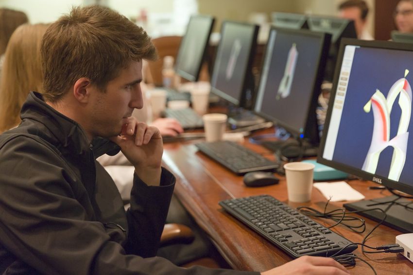
can be offloaded from the client level. The host manages user     Findings We found that our participants were extremely
sessions, stores and loads scene data from disk, performs ge-     comfortable with aspects of 3D visual navigation, even with
ometric manipulations (non-manifold meshing and incision          the very rudimentary orientation that was provided. Most
modeling) as a result of user actions, and runs collision de-     participants found the visual examples of procedures demon-
tection. This tier requires large amounts of memory, beyond       strated to be very enlightening, with many of them com-
what is natively offered on a GPU or Many-Core accelerator.       menting that this visual illustration was the most infor-
The third tier is the numerical solver, which executes all low-   mative exposure they had for procedures they only knew
level compute intensive kernels (but not combinatorial tasks      from reference literature (most of them had not witnessed
such as mesh generation). We have implementations that            these procedures in the operating room). Almost no par-
allow this layer to either run on the same CPU platform as        ticipant volunteered the lack of self-collision processing as
the 2nd-tier code or run natively on a Xeon Phi accelerator,      an observed omission, until the interviewer explicitly asked
interfacing with the host over MPI.                               them about this aspect (all demonstrations in our workshop
                                                                  entailed full suturing of wound closure). On the contrary,
                                                                  several participants identified inaccuracies in the elastic be-
7    Examples                                                     havior of the virtual tissues, finding that our models ap-
                                                                  peared to be more “permissive” to manipulation than real
For our clinical examples, we provided our senior domain          flesh tissue. An interface feature that was pointed out as
collaborators with a brief tutorial of our authoring interface    lacking, is the inability to appreciate (simply by looking at
and asked them to craft typical repair scenarios on a pre-        the final sutured result) the deformation patterns that have
pared model of the human scalp, as well as on a stock model       resulted from a certain repair; it was suggested that adding a
of a flat tissue sample. Our system captured a script of          texture (grid lines or checkerboard patterns) on the skin sur-
surgical manipulations, which was then re-run in an offline       face would be much more useful in evaluating tissue strain
setting using a higher resolution embedding lattice, with the     and deformation. We also received requests for biologically
intent to re-enact the same manipulation with higher detail.      inspired aids - in particular a visualization of anatomical el-
As a proof of concept, we bench-marked our system with a          ements such as blood vessels in the tissue being cut. Several
high resolution human body model with anisotropic active          users requested more traditional animation features, such as
musculature; details of the anisotropic material discretiza-      timeline scrubbing and history undo, as well as side-by-side
tion can be found in the supplemental technical document.         views of different repair approaches for visual comparison.
We report detail timings, including time taken at the indi-
vidual kernels of our solver, in Table 1.                         Limitations and future work Section 3 discusses a num-
                                                                  ber of conscious limitations in the interest of balancing per-
8    Evaluation and Discussion                                    formance and extensibility. From a research standpoint, our
                                                                  biggest perceived challenge is improving the accuracy of the
                                                                  constitutive models for the biomaterials involved. Full self-
Deployment To evaluate our system, we conducted a pi-
                                                                  collision support will be essential for extending our work to
lot deployment for the medical residents in the University of
                                                                  procedures that rely on contact, in addition to sutures, to
Wisconsin-Madison Plastic & Reconstructive Surgery pro-
                                                                  model properly. Finally, a large class of reconstructive pro-
gram, as part of a workshop on craniofacial reconstruction
                                                                  cedures cannot be modeled with all incisions performed at
techniques. We set up a local switched network at the lo-
                                                                  the beginning of time; a flexible topology change modeling
cation of the workshop, with a portable desktop-grade com-
                                                                  system would be necessary to incorporate a seamless ability
puter (with a 4-core Intel 4770R processor and 16GB RAM)
                                                                  for topology change, concurrent with deformation.
acting as the Tier 2/3 simulation server, and a collection of
eight Chromebox web-based thin clients as the user stations
(our setup can be seen in Figure 3). Although our modest          Acknowledgements
portable server did not have the computing power available
to our many-core accelerated server systems which we used         The authors are grateful to Dr. Timothy King, the medi-
for our large-scale offline simulations, its (AVX-accelerated)    cal residents of the Plastic & Reconstructive Surgery pro-
performance was more than adequate to deliver an interac-         gram, and the School of Medicine and Public Health at the
tive user experience. Total cost of the entire deployment,        University of Wisconsin-Madison for their support and par-
including server, networking and client stations was $4,000.      ticipation in this activity. We would like to acknowledge
                                                                  Aaron Oliker and BioDigital Systems for supplying the mod-
Participants were initially given an extremely brief orien-       els used in this project. Primary funding for this work was
tation on visual navigation within the application and its        provided by the NSF/NIH Smart and Connected Health pro-
interface. In first part of the deployment exercise, the work-    gram (IIS-1407282). E.S.is supported in part by NSF Grants
shop instructor (a seasoned user of the system) authored sev-     IIS-1253598, CNS-1218432, CCF-1423064, CCF-1438992.
eral different reconstructive procedures on different anatom-
ical models, while the participants were invited to follow
the manipulations as they were taking place (without affect-      References
ing them) by adjusting the view of the dynamic model on
their own station. Subsequently, individual participants who      Allard, J., Cotin, S., Faure, F., Bensoussan, P.-J.,
had no prior exposure to the system were invited to drive           Poyer, F., Duriez, C., Delingette, H., Grisoni, L.,
the authoring process, which their colleagues would virtu-          et al. 2007. SOFA - an Open Source Framework for
ally follow. The workshop instructor provided guidance on           Medical Simulation. In MMVR 15, IOS Press.
clinical aspects of the repair being authored, while questions    Baker, S. R. 2014. Local Flaps in Facial Reconstruction
about the user interface would be recorded and addressed            (3rd ed.). Saunders.
by the system developers. At the conclusion of the exercise,
the participants were debriefed and given the opportunity to      Bro-nielsen, M., and Cotin, S. 1996. Real-time Volu-
evaluate their experience and propose improvements.                 metric Deformable Models for Surgery Simulation using
Newton Update Add Add
Total Grid Mesh Compact UnCompact
Example Plat. Blocks Iteration State Force Differ.
Voxels Voxels Voxels (ms) (ms)
(s) (ms) (ms) (ms)
47689 47206 483 8821 0.3630 1.5 1.4 1.6 0.4 0.6
Xeon
Dufourmentel 294248 294015 233 47681 2.0648 7.8 5.1 4.2 2.1 3.0
Mouly
47689 47206 483 8821 0.4259 1.3 1.5 0.9 0.1 2.0
Phi
294248 294015 233 47681 0.7349 2.8 3.3 2.2 0.7 4.7
48529 47203 1326 6909 0.1620 1.1 0.9 0.7 0.2 0.4
Xeon
Rhomboid 879571 877362 2209 112302 2.4131 18.4 9.6 9.0 3.2 4.0
Flap
48529 47203 1326 6909 0.3735 1.3 1.4 1.0 0.1 1.5
Phi
879571 877362 2209 112302 1.1323 5.3 6.2 3.9 1.2 9.6
54003 49306 3697 6943 0.2293 1.2 0.5 0.9 0.3 0.5
Xeon
960810 957908 2902 127070 2.7707 20.5 9.3 10.1 3.6 4.5
ZPlasty
54003 49306 3697 6943 0.3814 1.3 1.4 1.1 0.1 1.5
Phi
960810 957908 2902 127070 1.2401 5.9 6.8 4.3 1.3 10.8
Xeon 2006903 2006903 0 265078 12.112 35.9 21.5 20.8 8.4 12.0
Human
Phi 2006903 2006903 0 265078 3.9608 11.4 16.3 7.8 3.3 16.2
Table 1: Performance results for various examples. Examples run on the Xeon platform used a 6-core Intel Xeon CPU
E5-1650 machine with 64 GB of memory, while the Phi examples ran on a 60-core Xeon Phi 5110P card with 8GB of memory.
All surgical examples were run with 50 conjugate gradient iterations while the human example was run with 100 iterations.
Finite Elements and Condensation. In Computer Graph- for the Operating Room: Proficiency-Based Training as
ics Forum, 57–66. a Paradigm Shift in Surgical Skills Training. Annals of
Surgery 241, 2.
Cavusoglu, M. C., Goktekin, T. G., and Tendick, F.
2006. GiPSi: A Framework for Open Source/Open Ar- Goktekin, T. G., Bargteil, A. W., and O’Brien, J. F.
chitecture Software Development for Organ-Level Surgi- 2004. A Method for Animating Viscoelastic Fluids. ACM
cal Simulation. Information Technology in Biomedicine, Trans. Graph. 23, 3 (Aug.), 463–468.
IEEE Transactions on 10, 2, 312–322.
Hermann, E., Raffin, B., and Faure, F. 2009. Interac-
Chen, D. T., and Zeltzer, D. 1992. Pump It Up: Com- tive Physical Simulation on Multicore Architectures. Eu-
puter Animation of a Biomechanically Based Model of rographics Association, EG PGV’09, 1–8.
Muscle Using the Finite Element Method. SIGGRAPH
Comput. Graph. 26, 2 (July), 89–98. Irving, G., Teran, J., and Fedkiw, R. 2004. Invertible
Finite Elements for Robust Simulation of Large Deforma-
Chentanez, N., Alterovitz, R., Ritchie, D., Cho, L., tion. Eurographics Association, SCA ’04, 131–140.
Hauser, K. K., Goldberg, K., Shewchuk, J. R., and
O’Brien, J. F. 2009. Interactive Simulation of Surgical Irving, G., Schroeder, C., and Fedkiw, R. 2007.
Needle Insertion and Steering. ACM Trans. Graph. 28, 3 Volume Conserving Finite Element Simulations of De-
(July), 88:1–88:10. formable Models. ACM Transactions on Graphics (SIG-
GRAPH Proc.) 26, 3.
Courtecuisse, H., and Allard, J. 2009. Parallel Dense
Gauss-Seidel Algorithm on Many-Core Processors. IEEE James, D. L., and Pai, D. K. 1999. ArtDefo: Accurate
CS Press, HPCC ’09, 139–147. Real Time Deformable Objects. ACM Press/Addison-
De, S., and Bathe, K. 2000. The method of finite spheres. Wesley Publishing Co., SIGGRAPH ’99, 65–72.
Computational Mechanics 25 , 329–345. Jerabkova, L., Bousquet, G., Barbier, S., Faure, F.,
De, S., Kim, J., Lim, Y.-J., and Srinivasan, M. A. and Allard, J. 2010. Volumetric modeling and interac-
2005. The point collocation-based method of finite spheres tive cutting of deformable bodies. Progress in Biophysics
(PCMFS) for real time surgery simulation. Computers & and Molecular Biology 103, 2-3 (Dec.), 217–224. Special
Structures 83, 17 - 18, 1515 – 1525. Issue on Biomechanical Modelling of Soft Tissue Motion.
Dick, C., Georgii, J., and Westermann, R. 2011. A Jeřábková, L., and Kuhlen, T. 2009. Stable Cutting
Hexahedral Multigrid Approach for Simulating Cuts in of Deformable Objects in Virtual Environments Using
Deformable Objects. IEEE Transactions on Visualization XFEM. IEEE Comput. Graph. Appl. 29, 2, 61–71.
and Computer Graphics 17, 11, 1663–1675.
Joshi, P., Meyer, M., DeRose, T., Green, B., and
Fan, Y., Litven, J., and Pai, D. K. 2014. Active Volu- Sanocki, T. 2007. Harmonic Coordinates for Charac-
metric Musculoskeletal Systems. ACM Trans. Graph. 33, ter Articulation. ACM Trans. Graph. 26, 3 (July).
4 (July), 152:1–152:9.
Kaufmann, P., Martin, S., Botsch, M., and Gross,
Gallagher, A. G., Ritter, E. M., Champion, H., Hig- M. 2009. Flexible Simulation of Deformable Models Using
gins, G., Fried, M. P., Moses, G., Smith, C. D., Discontinuous Galerkin FEM. Graph. Models 71, 4 (July),
and Satava, R. M. 2005. Virtual Reality Simulation 153–167.You can also read