Hierarchical Image Link Selection Scheme for Duplicate Structure Disambiguation - BMVC 2018
←
→
Page content transcription
If your browser does not render page correctly, please read the page content below

WANG et al.: HIERARCHICAL LINK SELECTION FOR SFM DISAMBIGUATION                                    i

Hierarchical Image Link Selection Scheme
for Duplicate Structure Disambiguation
Fan Wang                                                    Department of Computer Science
fan.wang.1@stonybrook.edu                                   Stony Brook University
Aditi Nayak                                                 New York, USA
adnayak@cs.stonybrook.edu
Yogesh Agrawal
yagrawal@cs.stonybrook.edu
Roy Shilkrot
roys@cs.stonybrook.edu

                                                     Abstract
            Repetitive and duplicate structures in urban areas have been a persistent problem in
       structure from motion (SfM). The resulting non-existent epipolar geometries (EGs) can
       significantly bias and complicate averaging algorithms and lead to incorrect camera po-
       sitions and structures in 3D reconstructions. We propose a lightweight pre-processing
       link selection scheme that produces an error-free camera trace which is used as direct
       inputs to a SfM pipeline. Images from local areas often share strong visual resemblance,
       however, correct view links bridging duplicate components are buried among many false
       links. The proposed scheme allows for independent expansions of local areas through
       a bottom up iterative grouping algorithm that exploits local resemblance. Independent
       components are then merged through links contributing to a global structure expansion
       selected by small scale reconstructions at joint positions. We demonstrate the effective-
       ness of our method on multiple laboratory and Internet-based image sets.

1     Introduction
Structure-from-motion (SfM) simultaneously estimates scene geometry and camera motions
from a 2D image set covering one or multiple scenes. While SfM methods have achieved
impressive results in general conditions, it remains a challenging task to effectively han-
dle duplicate structures commonly found in urban scenes. Such difficult conditions lead to
repeated, folded, and phantom structures, typically arising from structural ambiguities, i.e.
disparate structures with highly similar appearances. The epipolar geometries (EGs) com-
puted from these ambiguous correspondences are non-existent and they consequently yield
incorrect reconstructions.
    Fig. 1 gives an example scene heavy in duplicate structures where each face of the hotel
has very similar appearance. Incorrectly matched local feature correspondences from differ-
ent faces could result in a high volume of non-existent EGs. The locally expanded structures
for each face then superimpose on top of each other to give an erroneous reconstruction.
 c 2018. The copyright of this document resides with its authors.
It may be distributed unchanged freely in print or electronic forms.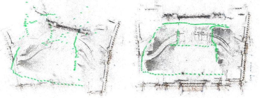
ii            WANG et al.: HIERARCHICAL LINK SELECTION FOR SFM DISAMBIGUATION

                                                        1
                                                               1

                                                                                   2

                                                        2

Figure 1: An example scene with large amount of duplicate structures. Left and middle
columns show images and constructions from two visually same but different parts of the
same hotel. Figure on top right corner is a correct reconstruction with our algorithm while
the bottom right demonstrates a structure collapse due to a false bridging link.

    Typical erroneous EGs are caused by incorrect feature descriptor correspondences, de-
generate configuration in camera pose estimation, or duplicate structures. The invalid EGs
computed from the first two cases are usually independent and inconsistent from each other
and thus, geometric cue based methods including residual check in rotation and translation
registration, rotation loop consistency analysis, triplets trifocal tensor fitting, and others can
be applied to address them. The EGs calculated from duplicate structures, however, are con-
sistent with each other and cannot be filtered simply by these methods. And it is this kind of
EGs that we strive to disambiguate.
    Current disambiguation methods often solve for duplicate structures by making addi-
tional assumptions. Missing correspondences are employed to identify invalid image pairs
from a third image within a triplet in less occluded scenes. Image timestamps are also used
in combination with missing correspondences for sequentially captured data. Our proposed
method does not attempt to keep many EGs in the view graph, instead it derives only a back-
bone from an original view graph where the possibility of finding a link between false image
pair is suppressed by a validation process that favors the expansion of the structures. An iter-
ative grouping scheme is first proposed to suggest candidate links hierarchically from local
neighborhoods to larger areas. These potential links are then validated by a small scale local
reconstruction at the joint of two groups. We argue that the images within a local neighbor-
hood of the scene often group correctly owing to the visual resemblance. The links suggested
to merge larger groups can be error prone in the presence of duplicate structures and cause
structure collapse. From fig.1, two instances of separate walls from the same hotel expand
correctly (middle column). An incorrect link leading to a structure collapse is shown at bot-
tom right while the correct reconstruction is given at top right. To show the effectiveness and
scalability of our method, we apply our backbone graph directly to the SfM process across
multiple image collections.
WANG et al.: HIERARCHICAL LINK SELECTION FOR SFM DISAMBIGUATION                             iii

   Our contributions include an iterative grouping scheme for hierarchical link suggestions
and a link validation process to avoid structure collapse.

2    Related work
Recently, duplicate structure disambiguation in SfM has garnered much interest from the re-
search community. Based on the characteristics of the techniques used, the existing methods
can be broadly categorized into three groups: missing correspondences, geometric reasoning
and topological reasoning.
    Missing correspondences based methods involve inference of an incorrect relationship
between two views from a third view in a triplet. Zach et al. [23] first introduce the idea of
missing correspondences analysis among image triplets. The absence of a notable portion of
correspondences found between the first and the second view from the third view indicates a
potentially erroneous EG between the first and the second view. Roberts et al. [15] estimate
ambiguous EGs with an expectation maximization (EM) framework by combining missing
correspondence cue and image time stamp information. Jiang et al. [9] extends the idea
of missing correspondences to minimize a global objective function which measures the
incorrectness of the 3D reconstruction assuming textured backgrounds. Cui and Tan [4]
integrate missing correspondence analysis into their recent work on similarity averaging for
global SfM methods.
    Geometric reasoning identifies potential erroneous EGs with calculated geometric in-
formation from feature correspondences. Yan et al. [21] present a geodesic consistency
measure to quantify and optimize the ambiguity of edge pairs given a path network obtained
from a set of iconic images deliberately selected through another optimization. The geodesic
relationship based resolution requires a pruned network that is less error-prone instead of a
plain matching graph. Zach et al. [24] infer conflicting geometric relations with a Bayesian
network from the cycles generated from a matching graph. A cycle is deemed consistent if
the chained transformations between image pairs along the loop return an identify map. The
emergence of false positives is indicated if the loop consistency is violated. Presumably, the
method is less effective with longer loops which are heavily biased by accumulated errors.
Heinly et al. [8] analyze conflicting observations of 2D features reprojected by reconstructed
3D structures. The proposed algorithm serves as a post-processing step to a reconstruction
by SfM. Cohen et al. [3] recover symmetry relations with geometric and appearance cues
and then use these relations as additional constraints in bundle adjustment.
    Topological reasoning analyze incorrect view pair relationship with a graph. Wilson
and Snavely [18] perform topological analysis over a bipartite visibility graph to detect bad
feature tracks. The method assumes separated background context of the confusing tracks
which might not always be true and potentially suffers from over-segmentation. Heinly et al.
[7] present another post-processing pipeline to effectively analyze the co-occurrence of 3D
points with local clustering coefficients (lcc).
    Other methods address related problems. Govindu [6] introduces a random sampling
scheme in the spirit of RANSAC [5] to remove outlier EGs in the matching graph. Wen-
Yan Lin et al. [12] propose RepMatch which reinforces a core-set found by observing the
micro-textures contained in repetitive structures with bilateral functions [11] embedded with
epipolar geometry. RepMatch is a feature matcher aiming at improving EGs that might not
even exist while we resolve the non-existent EGs. Li et al. [10] solves the problem of large
scale reconstruction with a combination of 2D appearance cues and 3D geometric constrains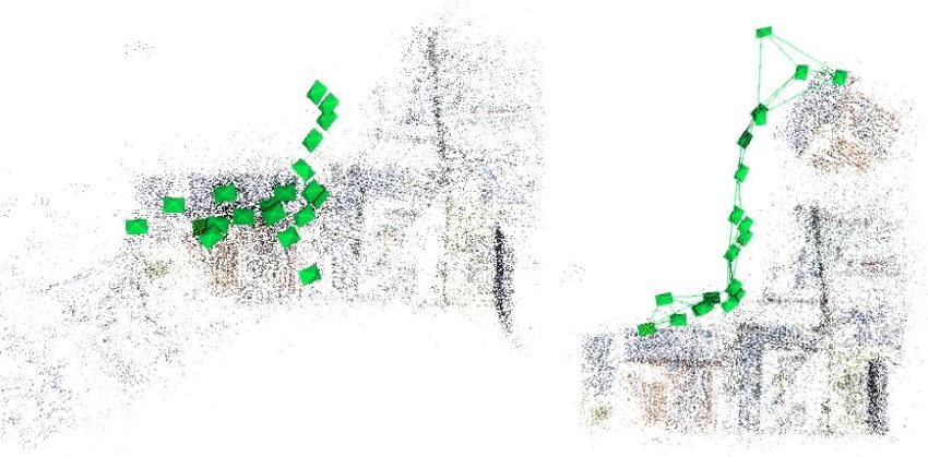
iv           WANG et al.: HIERARCHICAL LINK SELECTION FOR SFM DISAMBIGUATION

on Internet photo sets. Snavely et al. [16] present skeletal set selection to find a minimal set
of views in the view graph that represent the entire scene. Sweeney et al. [17] propose to
improve a viewing graph by enforcing loop consistency constraints before SfM procedure.
Ceylan et al. [2] present an optimization framework to extract repeated elements in images
of urban facades with a user-marked pattern. They focus more on improving valid EGs rather
than detecting non-existent EGs.

3       Overview
Independent expansions of the local components are generally correct during early stages
even in the presence of visually similar structures. Given the short Euclidean distance be-
tween the components in the collapsed 3D model which suggests strong visual resemblance,
at least one link should have already been chosen to merge these components in the previous
expansion iterations. We argue that erroneous links result in structure collapse. A hierarchi-
cal link suggestion scheme consisting of two passes, namely, minimum spanning tree (MST)
construction and iterative MST cut is first described below followed by a link validation
technique to avoid structure collapse.

3.1     Image link suggestion
To mimic local expansions of the neighborhoods, a bottom up grouping scheme is suggested
to first break the view graph into pieces which are then merged gradually through iterations.
We briefly describe the idea here and will provide details in the following sections. A min-
imum spanning tree (MST) is first constructed from a view graph which is then cut at its
weakest links until each partition contains at most two nodes. A link suggestion between
the two nodes is presented for validation in each partition. All partitions that pass the val-
idation will act as a single node and form a new view graph serving as input for the next
iteration of MST construction and split. The algorithm stops when only one node exists in
the view graph or every available link fails the validation process. The scheme can be better
understood with two loops. An outer loop in which each iteration is a MST construction and
an inner loop who iteratively cuts the MST. Each iteration in outer loop witnesses an entire
inner loop.

3.1.1    MST construction
The information of the relationships among view pairs can be described with a view graph
denoted as G = (V, E) where V is the set of vertices and E the edges. Each vertex of G is
an individual image and an edge ei j ∈ E exists when feature correspondences can be found
between image vi and v j . The weights associated with the edges can be any metric that
measures the similarity between two images such as the number of match inliers from fun-
damental matrix estimation. [8] formulates an edge cost that specifically addresses the issue
of duplicate structures. In this paper, the initial view graph G0 is derived from a computa-
tion of pairwise correspondences among all input images with SIFT descriptor [14] detected
by Affine-SIFT [22]. The resulting correspondences are then refined by a bilateral func-
tion matcher [13] to prevent premature model split in case of wide baseline view pair. The
number of filtered matches is assigned as edge weight for G0 .
WANG et al.: HIERARCHICAL LINK SELECTION FOR SFM DISAMBIGUATION v
1 2 3
v10 P
0
P30 v1
0
v10 2
e5 0
e1
0
e5 0
e1 0
e5 0
e10
v2 0
v50
v20
v5 0
v2 0
v50
Iteration 1
e100 e100 e100
e90 e60 P1 0 e 0 e90 e60 e20 e40 e90 e60 e20 P20
e40 e20 Repeatedly split G P1
0
0
4
e80 e7 0
e80 e7 0
until each set has e80 e70
at most two nodes.
v30 e30 v40 v30 e30 v40 v30 e30 v40
Initial view graph G (5 nodes), an MST
0
Cut minimum link 3and split G e0 0
End of first inner loop, G is split
0
is shown in red dotted lines. into two partitions P1 0 and P20 into 3 groups P 0 , P 0, and P 0
1 2 3
4 5 6 7
v31 P11 v 3
1
e50 e90 e10 e60 P1 2
e11
Iteration 2
Iteration 3
e21 e 11 e 21
2 2 v12 v22 v12 v22
e 12 e 12
v11 v21 v11 e 31 v21 P 1
e30 e70 e80 e100 2
e31
4
Construct graph G (3 nodes) from
1 Cut minimum link 2 and split Ge1 1
Construct graph G (2 nodes) from
2 Since there are only two nodes in G,2
into two groups P1 and P2 . End this marks the end of the algorithm.
1 1
step 3 and find an MST step 5 and find an MST
of second inner loop
Figure 2: An example of the hierarchical suggestion scheme with five nodes. 1 is an initial
view graph G0 (red dotted lines mark the MST). 2 and 3 are two steps in an inner loop
which split G0 into three partitions P10 , P20 , and P30 . 4 marks the second iteration of outer
loop which computes a new view graph G1 based on 3 using G0 . 5 finishes the current
inner loop with the only cut from e12 . At the third iteration of outer loop ( 6 ), the new view
graph G2 is a valid partition itself. The algorithm ends at 7 .
3.1.2 Iterative bottom up image grouping
Our hierarchical image link suggestion scheme is composed of two loops, namely, an outer
loop to construct MST and an inner loop to cut the MST. With the initial graph G0 ready,
the algorithm first enters the inner loop to cut G0 once every iteration from an edge with the
smallest weight until each resulting partition contains at most two nodes from G0 . In case
of two nodes inside a partition, a link between them is presented for validation. All single
node partitions and two node partitions passing the validation phase will behave like a single
node in the next iteration of outer loop. Accordingly, an updated view graph G1 is required to
compute a new MST in the next iteration. An edge e1i j is found between node v1i and v1j which
are logical nodes containing one or more images if the associated weight is greater than zero.
This weight is calculated as the summation of the top N edges with the largest weight values
from the initial graph G0 between image members inside v1i and v1j averaged by N. G1 is
then fed into an inner loop for split again after which we derive G2 . The same procedure
is repeated until there is only one node in the resulting graph which contains all images or
every suggested link fails the validation process. Note the difference between physical nodes
(images) and logical nodes (containing at least one image). The weights of each new view
graph have to come directly from the initial graph G0 instead of previous view graph except
of G1 . When two logical nodes fall into a same partition, a link from G0 is selected for actual
merging of the two image clusters so that they form a connected component and behave like
a single node in the next iteration. Note that this link is an image link rather than a link
between logical nodes. The selection strategy is rather simple: we choose the link with the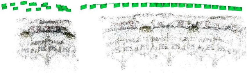
vi WANG et al.: HIERARCHICAL LINK SELECTION FOR SFM DISAMBIGUATION
largest weight. This link will also be submitted for validation. However, computation of
even a local reconstruction for each suggested link still poses considerable cost. This issue
is addressed in section 3.2.2.
Fig.2 illustrates this hierarchical scheme with a simplified example consisting of 5 nodes.
The outer loop for spanning tree construction and inner loop for graph cut operate in turn to
group images in a bottom-up fashion and suggest links hierarchically. 1 is an initial view
graph G0 with constructed MST marked with red dotted lines. The algorithm enters the inner
loop from 2 where a MST edge e03 is identified as the weakest. The cut from e03 results in
two partitions illustrated in gray shaded ellipses ({v02 , v03 } and {v01 , v04 , v05 }) of G0 . The inner
loop stops at 3 with G0 further split into three partitions each of which contains at most
two nodes from a second MST edge e01 . 4 shows the second iteration of outer loop which
computes an updated view graph G1 from which it builds a new MST. Notice that the nodes
in G1 are logical nodes (v11 = {v02 , v03 }, v12 = {v04 , v05 }, and v13 = {v01 }) and the new weights are
calculated as the averaged summations of all the edge weights between image members of
each logical node assuming infinite value of parameter N. 5 marks the end of second inner
loop with e12 separating G1 into two partitions P11 and P21 . New view graph G2 is shown in 6
which is a valid partition itself. The outer loop stops at 7 with only one node containing all
images in the new graph.
The proposed iterative grouping scheme makes linkage suggestion hierarchically from
smaller groups of local neighborhoods to areas containing hundreds of images. The confi-
dence of these suggestions decrease as the hierarchy goes up. We note that the edges added
in the first iteration are correct most of the times. As the construction proceeds, more and
more correctly linked images participate in the process of deciding new links. In the pres-
ence of ambiguous structures, the suggested links at higher hierarchy often point directly to
the duplicate counterparts.
3.2 Image Link Validation
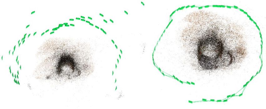
Fig.3 presents an example scene where two identical oat boxes are placed at different loca-
tions. The hierarchical link suggestion scheme ensures the local neighborhood around each
oat box expands correctly and images are grouped into two clusters L and R . Without
link validation, the view pair in the upper middle of fig.3 which shares stronger visual re-
semblance is selected for merging which causes a collapse of the structure (shown in upper
right). The lower middle image pair proves to be the right link which unfortunately has
the widest baseline among all pairs. The correct reconstruction is given in the bottom right
corner of fig.3.
3.2.1 Structural collapse measurement
The intuition behind our link validation is that if a connection made in a later stage cause
a structure collapse bringing two sets of cameras close to each other, then these two groups
should have already been merged before the current stage given the short Euclidean distance
between cameras in the resulting reconstruction. The structure of the target scene is supposed
to expand with addition of photos. Therefore, a valid link is the one that helps to expand
the structures while a bad link leads to a collapse. From fig.3, the distance between left
box ( L ) and right box ( R ) is stretched in the correct reconstruction while it shrinks in
the incorrect one.We perform a small scale reconstruction only at the joint position of the
groups to constrain computation costs. C(≤ 3) nearest cameras taken from each side of the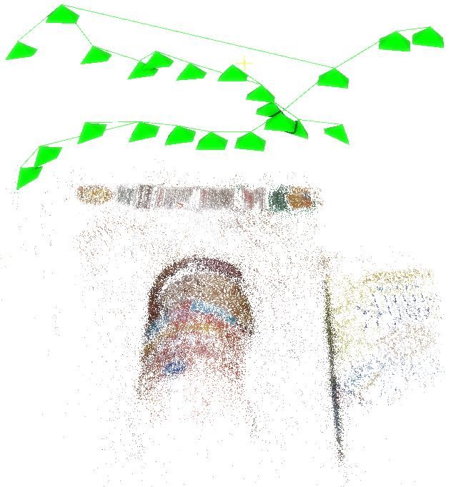
WANG et al.: HIERARCHICAL LINK SELECTION FOR SFM DISAMBIGUATION                              vii

joint (the suggested link) form a miniature reconstruction to determine the quality of the link.
We define the correctness of the suggested link with a validation score as below:
                               maxc1 ,c2 ∈L D(c1 , c2 ) + maxc1 ,c2 ∈R D(c1 , c2 )
                     score =                                                                (1)
                                            maxc1 ,c2 ∈M D(c1 , c2 )
where L and R each is a group of C + 1 (C nearest views plus the closer view on the link)
cameras from opposite side of the joint and M is the merged camera group. D(c1 , c2 ) com-
putes the camera distance in Euclidean space. A score with lower value in general indicates
a link with better quality. The specific use of the scores is described in the next part.

           L                         False pair

                                                         L        False link

                                                             R

           R                     Correct pair

                                                     L            Correct link       R

Figure 3: The neighborhoods of two identical oat boxes expand correctly ( L and R ). The
global structure of the scene collapses (top right) when merged with a faulty link (marked in
red) while a correct link (in blue) expands the structures (bottom right).

3.2.2   Potential erroneous link detection
Though it might be tempting to check every link suggested by the hierarchical scheme, the
costs associated are considerable even with a local reconstruction. To constrain the costs,
we present a two-level error detection process to submit only the links that are potentially
bad for further verification. Based on the characteristics of the hierarchical scheme, we
ask two questions: (L1) Is it correct to merge the two logical nodes (image clusters) in
the same partition; (L2) If the decision to combine those two logical nodes is right, is the
image link chosen for actual merging also correct. Imagine a target scene consisting of three
components: duplicate structures A and B and a central component C bridging A and B. A
decision to merge {A} and {B} directly is incorrect and is a L1 error. A decision to merge
{A,C} and {B} is correct but the image link selected for actual merging could still come
from those between image members of A and B because of the similarity of the duplicate
structures. This kind of errors is referred to as L2 errors.
    L1 errors are identified with different choices of N values introduced in section 3.1.2.
The system makes L1 decisions solely based on the strongest link if N = 1 and makes more
informed decisions accounting for the N best top links otherwise. A decision oscillation
triggering the link verification is detected when decisions made by different values of N do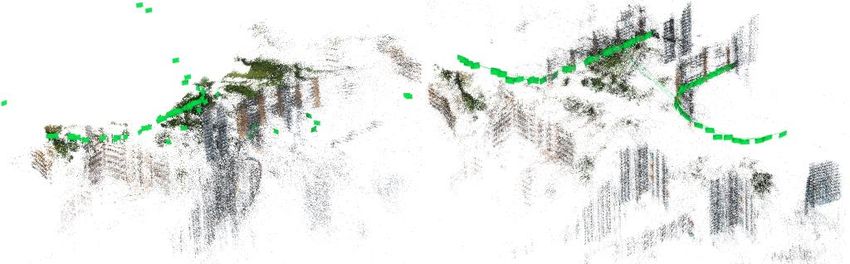
viii         WANG et al.: HIERARCHICAL LINK SELECTION FOR SFM DISAMBIGUATION

not reach consensus. An oscillation indicates a lack of confidence of the made decision
and might cause structure collapse. Two values of N (1 and 5) are adopted throughout the
algorithm to detect such oscillations. In the presence of oscillation, a validation score from
eq.1 will be computed for each involved decision and the algorithm proceeds with the one
carrying the smallest score value. To suppress the L2 errors, the image link with the smallest
value of validation score is chosen for group merging among the top 15 links with the largest
weights.

4      Experiments
We evaluate our algorithm on a wide variety of photo collections including both indoor and
outdoor scenes. To estimate the robustness of our proposed method, the output camera trace
is directly applied to the VisualSFM [20] for reconstructions. VisualSFM is also used for
local reconstruction for link validations. For each dataset, the images are resized so that
the longer sides are 640 pixels with aspect ratio intact. Though not required, our scheme
works best with Affine-SIFT[22] as feature detector which helps reinforce the neighbor-
hoods of the images with simulations across tilts. A GPU implementation of Affine-SIFT
is used throughout the experiments with tilt as 5 and other parameters untouched. To avoid
premature split of the models, a bilateral function filter[13] is adopted with default param-
eters to produce reliable matches. Two values of N (1 and 5) are used to generate deci-
sion oscillations. To contain computation cost, we empirically chose C = 2 nearest cameras
from each side of the joint link which sums to 6 cameras at most (including 2 cameras
on the link) to conduct a local reconstruction. The performance statistics below are re-
ported from a 64bit Linux platform with 32GB RAM and an i7-5820K Intel CPU. A C++
implementation of our work can be found at https://github.com/seravee08/
Hierarchical-Link-Selection-for-Disambiguation-. Our method is first
evaluated on benchmark datasets (I,II, III, IV, VI, VII, and X) followed by two Internet-based
photo collections (XII and XIII) consisting of 2304 and 1450 images respectively. The pro-
posed scheme is finally tested on four very challenging datasets (V, VIII, IX, and XI) with
either wide-baseline nature or large volume of repetitive structures.
     Table 1 compares our algorithm with three state-of-arts methods in the literature. The
datasets along with their sources are listed in the first column while the second column re-
ports the number of images from each sequence. As no source codes can be obtained from
[21], we can only report here the numbers from their papers. The time shown for [18] in-
cludes only computation time. While [18] does not segment a correct input construction
(I), it fails to correct for II, III, VIII, or IX and does not produce outputs for XII or XIII.
It also cuts more than 75% tracks for sequence VI. While the algorithm performs generally
well with larger datasets at a superior speed, it can suffer from over-segmentation with its
aggressive track removal strategy (VI and VII) and visually indistinguishable structures as
well. Additionally, user needs to indicate a desired number of components beforehand which
makes it hard to quantify the number of connected components. As a post-processing algo-
rithm which takes reconstructions as inputs, [8] performs reasonably well on datasets with
sufficient background information that can be used for conflicting observation inference. As
a consequence, it fails on II and XI due to a lack of textured backgrounds. In case of a high
volume of similar patterns like IV and IX or wide baseline view pairs like VIII,[8] does not
produce satisfying results. Meanwhile, it exhausts our computation resources running huge
datasets like X, XII, and XIII partially because of the use of SLIC [1].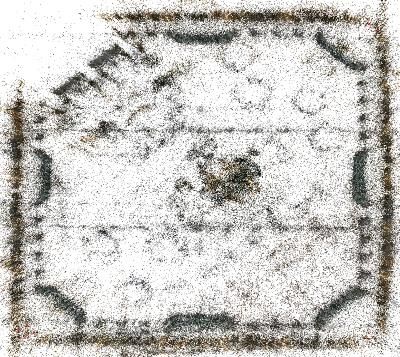
WANG et al.: HIERARCHICAL LINK SELECTION FOR SFM DISAMBIGUATION                                 ix

         Dataset                   #cameras                 Time
                                             Ours     [21]∗     [18]     [8]
         I. Books                20          0.32s    -         0.86s    1.08m
         II. Cup [9]             64          8.44s    27s       ×        16.90s
         III. Street [15]        19          0.04s    -         ×        6.15s
         IV. Indoor [9]          154         2.07m    -         41.39s 15.70s
         V. FC                   151         2.49m    -         15.09s 12.14m
         VI. BB [8]              392         6.58m    -         8.01s    1.56m
         VII. RC [8]             282         2.33m    1.2m      37.79s 33.18s
         VIII. TopTop[12]        65          29.92s -           ×        49.01s
         IX. HDB [12]            69          18.30s -           ×        18.15s
         X. SC [18]              5338        81.3m    51.4m     14.23m -
         XI. ToH [9]             338         7.48m    2.0m      13.13m -
         XII. RF [19]            2304        42.2m    -         ×        -
         XIII. GM [19]           1500        34.3m    -         ×        -
Table 1: Performance of our algorithm on different photo collections. From top to bottom,
the datasets respectively are Books, Cup, Street, Indoor, Forbidden City, Big Ben, Rad-
cliffe Camera, Top Top, HDB, Sacre Coeur,Temple of Heaven, Roman Forum and Gen-
darmenmarkt. Ncameras and N pc indicate the number of input cameras and reconstructed 3D
points respectively.

    Fig. 4 visually shows the reconstruction results of our algorithm. The left and right half
of each cell are reconstructions from VisualSFM without and with our algorithm respectively.
The structure of IV is perfectly recovered (lift lobby on bottom left). Our method also
retrieves a correct view pair for VI to avoid collision of structures from left and right sides of
the tower. VII is split because of the insufficient coverage of cameras between two facades
while X is a dataset consisting of disparate structures in nature and thus, reconstructions
corresponding to three different parts are shown. The presented method in this paper scales
well for larger datasets like X, XII, and XIII. Cell XII illustrates two isolated reconstructions
for each facade of the gate while our algorithm manages to merge those two faces into a
unique structure. Interestingly, we output a daytime model (middle) and night model (right)
separately for XIII with a corrupted model shown on the left. Photos from VIII are taken
with wide-baselines between each image pair from roofs of two different buildings while
the pictures from IX are taken at a close range from the target building which has excessive
amount of repetitive structures. V proves to be difficult as one single erroneous EG can cause
skewed reconstructions.

5    Conclusion
We present a lightweight bottom up image neighborhoods expansion scheme to suggest view
pair hierarchically to a validation process which explicitly avoids structure collapse. To
contain computation cost, we perform local reconstructions at the joints of adjacent neigh-
borhoods and propose a two-level error detection process to submit only suspicious links
for further validation. The proposed method is experimentally shown to work on multiple
challenging datasets including both laboratory and Internet based photo collections.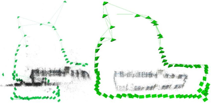
x                  WANG et al.: HIERARCHICAL LINK SELECTION FOR SFM DISAMBIGUATION

    I Books                  II Cup                         III Street

    IV Indoor                           V Forbidden City

    VI Big Ben                             VII Radcliffe Camera

    VIII Top Top                                           IX HDB

    X Sacre Coer                                           XI Temple of Heaven

    XII Roman Forum

    XIII Gendarmenmarkt

Figure 4: Results of our method on multiple challenging datasets (indoor and outdoor, lab-
oratory and Internet-based). The left and right model from each cell is a reconstruction by
VisualSFM [20] without and with our filtered camera trace respectively.
WANG et al.: HIERARCHICAL LINK SELECTION FOR SFM DISAMBIGUATION xi
References
[1] Radhakrishna Achanta, Appu Shaji, Kevin Smith, Aurelien Lucchi, Pascal Fua, and
Sabine Susstrunk. Slic superpixels compared to state-of-the-art superpixel methods.
IEEE Trans. Pattern Anal. Mach. Intell., 34(11):2274–2282, November 2012. ISSN
0162-8828. doi: 10.1109/TPAMI.2012.120. URL http://dx.doi.org/10.
1109/TPAMI.2012.120.
[2] Duygu Ceylan, Niloy J. Mitra, Youyi Zheng, and Mark Pauly. Coupled structure-
from-motion and 3d symmetry detection for urban facades. ACM Trans. Graph., 33:
2:1–2:15, February 2014. ISSN 0730-0301. doi: 10.1145/2517348. URL http:
//doi.acm.org/10.1145/2517348.
[3] A. Cohen, C. Zach, S. N. Sinha, and M. Pollefeys. Discovering and exploiting 3d
symmetries in structure from motion. In 2012 IEEE Conference on Computer Vision
and Pattern Recognition, pages 1514–1521, June 2012. doi: 10.1109/CVPR.2012.
6247841.
[4] Z. Cui and P. Tan. Global structure-from-motion by similarity averaging. In 2015 IEEE
International Conference on Computer Vision (ICCV), pages 864–872, Dec 2015. doi:
10.1109/ICCV.2015.105.
[5] Martin A. Fischler and Robert C. Bolles. Random sample consensus: A paradigm for
model fitting with applications to image analysis and automated cartography. Commun.
ACM, 24(6):381–395, June 1981. ISSN 0001-0782. doi: 10.1145/358669.358692.
URL http://doi.acm.org/10.1145/358669.358692.
[6] Venu Madhav Govindu. Robustness in motion averaging. In Proceedings of the 7th
Asian Conference on Computer Vision - Volume Part II, ACCV’06, pages 457–466,
Berlin, Heidelberg, 2006. Springer-Verlag. ISBN 3-540-31244-7, 978-3-540-31244-4.
doi: 10.1007/11612704_46. URL http://dx.doi.org/10.1007/11612704_
46.
[7] J. Heinly, E. Dunn, and J. M. Frahm. Recovering correct reconstructions from indis-
tinguishable geometry. In 2014 2nd International Conference on 3D Vision, volume 1,
pages 377–384, Dec 2014. doi: 10.1109/3DV.2014.84.
[8] Jared Heinly, Enrique Dunn, and Jan-Michael Frahm. Correcting for duplicate scene
structure in sparse 3d reconstruction. In David Fleet, Tomas Pajdla, Bernt Schiele,
and Tinne Tuytelaars, editors, Computer Vision – ECCV 2014, pages 780–795, Cham,
2014. Springer International Publishing. ISBN 978-3-319-10593-2.
[9] N. Jiang, P. Tan, and L. F. Cheong. Seeing double without confusion: Structure-from-
motion in highly ambiguous scenes. In 2012 IEEE Conference on Computer Vision and
Pattern Recognition, pages 1458–1465, June 2012. doi: 10.1109/CVPR.2012.6247834.
[10] Xiaowei Li, Changchang Wu, Christopher Zach, Svetlana Lazebnik, and Jan-Michael
Frahm. Modeling and recognition of landmark image collections using iconic scene
graphs. In Proceedings of the 10th European Conference on Computer Vision: Part I,
ECCV ’08, pages 427–440, Berlin, Heidelberg, 2008. Springer-Verlag. ISBN 978-3-
540-88681-5. doi: 10.1007/978-3-540-88682-2_33. URL http://dx.doi.org/
10.1007/978-3-540-88682-2_33.xii WANG et al.: HIERARCHICAL LINK SELECTION FOR SFM DISAMBIGUATION
[11] Wen-Yan Lin, Ming-Ming Cheng, Jiangbo Lu, Hongsheng Yang, Minh N. Do, and
Philip Torr. Bilateral functions for global motion modeling. In ECCV, 2014.
[12] Wen-Yan Lin, Siying Liu, Nianjuan Jiang, Minh. N. Do, Ping Tan, and Jiangbo Lu.
Repmatch: Robust feature matching and pose for reconstructing modern cities. In
Bastian Leibe, Jiri Matas, Nicu Sebe, and Max Welling, editors, Computer Vision –
ECCV 2016, pages 562–579, Cham, 2016. Springer International Publishing. ISBN
978-3-319-46448-0.
[13] Wen-Yan Lin, Fan Wang, Ming-Ming Cheng, Sai-Kit Yeung, Philip H. S. Torr, Minh N.
Do, and Jiangbo Lu. CODE: coherence based decision boundaries for feature cor-
respondence. IEEE Trans. Pattern Anal. Mach. Intell., 40(1):34–47, 2018. doi:
10.1109/TPAMI.2017.2652468. URL https://doi.org/10.1109/TPAMI.
2017.2652468.
[14] David G. Lowe. Distinctive image features from scale-invariant keypoints. Interna-
tional Journal of Computer Vision, 60(2):91–110, Nov 2004. ISSN 1573-1405. doi:
10.1023/B:VISI.0000029664.99615.94. URL https://doi.org/10.1023/B:
VISI.0000029664.99615.94.
[15] R. Roberts, S. N. Sinha, R. Szeliski, and D. Steedly. Structure from motion for scenes
with large duplicate structures. In CVPR 2011, pages 3137–3144, June 2011. doi:
10.1109/CVPR.2011.5995549.
[16] N. Snavely, S. M. Seitz, and R. Szeliski. Skeletal graphs for efficient structure from
motion. In 2008 IEEE Conference on Computer Vision and Pattern Recognition, pages
1–8, June 2008. doi: 10.1109/CVPR.2008.4587678.
[17] C. Sweeney, T. Sattler, T. HÃűllerer, M. Turk, and M. Pollefeys. Optimizing the view-
ing graph for structure-from-motion. In 2015 IEEE International Conference on Com-
puter Vision (ICCV), pages 801–809, Dec 2015. doi: 10.1109/ICCV.2015.98.
[18] K. Wilson and N. Snavely. Network principles for sfm: Disambiguating repeated struc-
tures with local context. In 2013 IEEE International Conference on Computer Vision,
pages 513–520, Dec 2013. doi: 10.1109/ICCV.2013.69.
[19] Kyle Wilson and Noah Snavely. Robust global translations with 1dsfm. In David Fleet,
Tomas Pajdla, Bernt Schiele, and Tinne Tuytelaars, editors, Computer Vision – ECCV
2014, pages 61–75, Cham, 2014. Springer International Publishing. ISBN 978-3-319-
10578-9.
[20] Changchang Wu. VisualSfM: A visual structure from motion system. 2011. URL
http://ccwu.me/vsfm/.
[21] Q. Yan, L. Yang, L. Zhang, and C. Xiao. Distinguishing the indistinguishable: Ex-
ploring structural ambiguities via geodesic context. In 2017 IEEE Conference on
Computer Vision and Pattern Recognition (CVPR), pages 152–160, July 2017. doi:
10.1109/CVPR.2017.24.
[22] Guoshen Yu and Jean-Michel Morel. Asift: An algorithm for fully affine invariant
comparison. 1, 02 2011.WANG et al.: HIERARCHICAL LINK SELECTION FOR SFM DISAMBIGUATION xiii
[23] C. Zach, A. Irschara, and H. Bischof. What can missing correspondences tell us about
3d structure and motion? In 2008 IEEE Conference on Computer Vision and Pattern
Recognition, pages 1–8, June 2008. doi: 10.1109/CVPR.2008.4587707.
[24] C. Zach, M. Klopschitz, and M. Pollefeys. Disambiguating visual relations using loop
constraints. In 2010 IEEE Computer Society Conference on Computer Vision and Pat-
tern Recognition, pages 1426–1433, June 2010. doi: 10.1109/CVPR.2010.5539801.You can also read