High End Systems Lonestar - Automated Luminaire User Manual Version 1.3.0 - Sim.ru
←
→
Page content transcription
If your browser does not render page correctly, please read the page content below

High End Systems
                 Lonestar
Automated Luminaire User Manual
                                 Version 1.3.0

                 Part Number: 2550M1200-1.3.0 Rev: A
                                   Released: 2021-08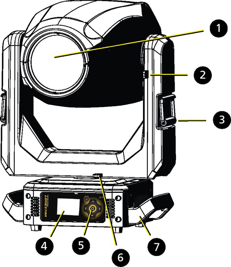
To view a list of ETC trademarks and patents, go to etcconnect.com/ip. All other trademarks, both marked
and not marked, are the property of their respective owners.
You can find complete High End Systems terms and conditions and warranty information at
etcconnect.com/Support/Warranty.aspx.
ETC intends this document, whether printed or electronic, to be provided in its entirety.
Table of Contents

       Introduction                                     1

                Important Safety Information            1

                Help from Technical Services            2

       Safety Considerations                            3

                General Operation and Use Guidelines    5

       Fixture Overview                                 6

       Install the Fixture                              7

       Power                                           10

                Electrical Specifications              10

                Input and Power Factor                 10

                Fixtures per Circuit                   10

                Connector Specification                11

       DMX Control                                     12

                DMX Connector Pinout                   12

                Connect DMX Cables to Fixture          12

                DMX Control and Ethernet Output        13

                Terminate DMX                          13

                Set the DMX Start Address              13

                DMX Channels                           13

Table of Contents                                           i
Ethernet Control 14
Connect Ethernet Cables to a Fixture 14
Ethernet Control and DMX Thru 15
Terminate DMX 15
Set the DMX Start Address 15
Set the Control Input and Universe 15
Configure the Fixture 16
Navigate the User Interface 16
Set Fixture Parameters 17
DMX Address 17
Info Menu 17
Set Menu 18
Test Menu 22
Preset Menu 22
Install the Heavy Diffusion Accessory 23
Error Codes 26
Maintenance 29
Clean the Fixture 29
Replace the Fuse 29
Compliance 29
ii Lonestar User ManualIntroduction
Congratulations on your purchase of the Lonestar automated framing fixture. This manual
provides important information for the safe installation, configuration, and maintenance of your
Lonestar fixture.
Important Safety Information
Please read all instructions prior to assembling, mounting, and operating this equipment.
Continued and safe operation of this fixture is the responsibility of the operator. This manual will
give tips for that continued safe operation. At any time please contact Technical Services for any
safety concerns.
The following international note, caution, and warning symbols appear in margins throughout
this manual to highlight important messages.
Note: Notes are helpful hints and information that is supplemental to the main text.
CAUTION: Hot Surfaces. This statement indicates that while operating,
equipment surfaces may reach very high temperatures. Allow the fixture
to cool before handling or servicing.
CAUTION: A Caution statement indicates situations where there may be
undefined or unwanted consequences of an action, potential for data loss or
an equipment problem.
WARNING: A Warning statement indicates situations where damage may
occur, people may be harmed, or there are serious or dangerous
consequences of an action
WARNING: RISK OF ELECTRIC SHOCK! This warning statement indicates
situations where there is a risk of electric shock.
All ETC High End Systems documents are available for free download from our website:
etcconnect.com/Products/High-End-Systems.
Please email comments about this manual to: TechComm@etcconnect.com.
Introduction 1Help from Technical Services
If you are having difficulties and your problem is not addressed by this document, try the ETC
support website at support.etcconnect.com or the High End Systems product website at
etcconnect.com/Products/High-End-Systems. If none of these resources are sufficient, contact
ETC Technical Services directly at one of the offices identified below. Emergency service is
available from all offices outside of normal business hours.
When calling for help, take these steps first:
l Prepare a detailed description of the problem
l Go near the equipment for troubleshooting
l Find your notification number if you have called in previously
ETC, Inc. ETC GmbH
Americas Germany, Austria, Switzerland,
Eastern Europe, and Russia
Technical Services Department
3031 Pleasant View Road Technical Services Department
Middleton, WI 53562 Ohmstrasse 3
800-775-4382 (USA, toll-free) 83607 Holzkirchen, Germany
+1-608 831-4116 +49 (80 24) 47 00-0
service@etcconnect.com techserv-germany@etcconnect.com
ETC Austin ETC France
High End Systems Products France
Technical Services Department Zone Urbaparc -
2105 Gracy Farms Lane Bâtiment E
Austin, TX 78758 USA 6 Boulevard de la Libération
800-890-8989 (USA, toll-free) Saint-Denis, 93200
+1-512 836-2242 +33 1 4243 3535
hesservice@etcconnect.com techservfrance@etcconnect.com
ETC Ltd ETC Asia
Europe, Middle East, and Africa Asia
Technical Services Department Technical Services Department
26-28 Victoria Industrial Estate Room 1801, 18/F
Victoria Road, Tower 1, Phase 1 Enterprise Square
London W3 6UU England 9 Sheung Yuet Road
+44 (0)20 8896 1000 Kowloon Bay, Kowloon, Hong Kong
techservltd@etcconnect.com +852 2799 1220
techserv-asia@etcconnect.com
2 Lonestar User ManualSafety Considerations
To ensure safe operation, follow the safety instructions and warning notes in this user manual.
l The Lonestar is intended for professional use only. Not for residential use. Read the entire
manual before using this equipment.
l Contact your ETC authorized dealer or Technical Services before performing any service in
order to maintain warranty coverage.
Symbols used on the product label are defined below:
The luminaire must be installed at least 3.0 m (9 ft Le luminaire doit être installé à au moins 3,0 m (9 pi.
3.0 m 10 in) away from all lighted objects. 10 po.) de tout objet éclairé.
General warning Avertissement général
Ne pas regarder la source de lumière lorsqu’elle
Do not stare at the operating light source.
fonctionne.
This product should not be discarded as unsorted Ce produit ne doit pas être jeté avec les déchets
waste but must be sent to separate collection ménagers mais doit être déposé dans une collecte de
facilities for recovery and recycling. déchets électroniques ou dans un point de collecte.
t a or Ta Rated maximum ambient temperature Température ambiante maximale recommandée
t c or Tc Rated maximum case temperature Température maximale recommandée pour le boîtier
Operate indoors only, not where this product Ne fonctionne qu'à l'intérieur, pas là où ce produit
would be exposed to the weather. serait exposé aux intempéries.
WARNING: Note the following safety warnings before use:
l This equipment is designed for operation by qualified personnel only.
l Replace fuses with the specified type and rating only. See page 29 .
l Make sure that the available voltage is within the stated range. See
page 10 .
l Do not use this fixture with a damaged power lead (cord set). If the lead
is damaged, it must be replaced by a qualified technician with an
equivalent type before use. Contact your local authorized dealer for
spare power leads.
l Do not use this fixture if the lens is damaged. Damaged lenses must be
replaced before use. Contact your local authorized dealer for a
replacement.
l Do not mount the fixture on or near flammable surfaces.
l Minimum distance from fixture head to combustible materials:
0.1 m (4 in).
l Minimum distance to lighted objects: 3.0 m (9 ft 10 in).
Safety Considerations 3AVERTISSEMENT : Pour votre sécurité, lisez les mises en garde et les avis
suivants avant toute utilisation :
l Cet équipement est conçu pour être utilisé par un personnel qualifié
uniquement.
l Remplacez les fusibles uniquement par le type et le calibre indiqués.
Voir page 29 .
l Veillez à ce que la tension disponible soit dans la plage indiquée.Voir
page 10 .
l N'utilisez pas ce projecteur avec un cordon d'alimentation endommagé
(fils électriques). Si le cordon est endommagé, un technicien qualifié
doit le remplacer par un cordon de type équivalent avant que l'appareil
ne puisse être utilisé. Contactez votre distributeur agréé local pour
obtenir des cordons d'alimentation de rechange.
l N'utilisez pas cet appareil si la lentille est endommagée. Les lentilles
endommagées doivent être remplacées avant l'utilisation. Contactez
votre revendeur agréé local pour un remplacement.
l Ne pas installer le projecteur sur ou à côté d’une surface inflammable.
l Distance minimum entre la tête du luminaire et les matériaux
combustibles : 0.1 m (4 in).
l Distance minimale avec les objets éclairés : 3.0 m (9 ft 10 in).
WARNING: RISK OF ELECTRIC SHOCK!
l Do not operate this device with the cover open.
l Disconnect the fixture from power and DMX and allow it to cool before
performing any cleaning and maintenance.
AVERTISSEMENT : RISQUE DE CHOC ÉLÉCTRIQUE!
l N'utilisez pas cet appareil avec le couvercle ouvert.
l Débrancher la lampe de son alimentation et du DMX et la laisser
refroidir avant d’effectuer un nettoyage ou un entretien.
RISK GROUP 2: CAUTION. Possibly hazardous optical radiation emitted
from this product. Do not stare at operating lamp. May be harmful to the
eyes.
GROUPE DE RISQUE 2 (RISQUE MODÉRÉ) : ATTENTION. Rayonnement
optique potentiellement dangereux émis par ce produit. Ne regardez pas la
lampe en fonctionnement. Peut être nocif pour les yeux.
CAUTION: Hot Surfaces. Allow the device to cool completely before
handling and servicing.
ATTENTION : Surfaces chaudes. Laissez le luminaire refroidir complètement
avant de le manipuler et de procéder à son entretien.
Note: The light source in this luminaire is not user-replaceable, and must be replaced
only by a qualified technician. Contact ETC Customer Support for assistance.
4 Lonestar User ManualGeneral Operation and Use Guidelines
l This fixture is only allowed to be operated with the maximum alternating current that is
stated in the technical specifications label provided on the fixture.
l Lighting effects are not designed for permanent operation. Consistent operation breaks may
extend the life of the fixture.
l When choosing the installation location, make sure the fixture will not be exposed to
extreme heat, moisture, or dust.
l Do not point the lens toward the sun or other bright light source. Doing so could damage the
fixture.
l If using the supplied Omega brackets with quick-locking thumb screws for fixture hanging,
ensure that the thumb screws have engaged a complete 90-degree positive latch.
l Operate the fixture only after having familiarized yourself with its functions. Do not permit
persons who are not qualified and familiar with its functions to operate the fixture.
l Do not modify the fixture. Any modifications will void the warranty.
l This manual describes the proper installation and operation of this fixture. Using this fixture
in any way other than the intended use may cause damage and void the warranty.
l When the fixture has been stored or transported in cold temperatures, allow it to warm to
room temperature for a minimum of one hour before applying power. Applying power to a
cold fixture may cause damage to the fixture and void the manufacturer warranty.
l When you power on the fixture, you may notice smoke or odor. This is normal and should
decrease gradually. If smoke or odor persists, disconnect the fixture from power and contact
your ETC dealer or Technical Services.
l Please use the original packaging if the fixture is to be transported. ETC will not be
responsible for the fixture if packaging other than manufacturer provided packaging is used.
Safety Considerations 5Fixture Overview
For complete technical specifications of the Lonestar fixture, see the technical datasheet:
etcconnect.com/Products/High-End-Systems/Lighting-Fixtures/Lonestar/Documentation.aspx
1: Lens
2: Tilt lock
3: Yoke handle
4: Display
5: Navigation controls
6: Pan lock
7: Handle
8: Ethernet ports (x2)
9: DMX Thru
10: DMX In
11: Power In
12: USB
13: Power Out
6 Lonestar User ManualInstall the Fixture
WARNING:
l NEMA Type 1 enclosure, indoor use, dry locations only. Do not use
outdoors. This fixture is intended for use where humidity does not
exceed 90% (non-condensing).
l The operating temperature range for this fixture is -10°C to 40°C (14°F
to 104°F). Do not operate the fixture outside of this range.
l The installation location must support a minimum point load of 10 times
the weight of the fixture.
l The installation must always be secured with a secondary safety
attachment. An appropriate safety cable is supplied.
l Safety cable attachment must be rated by a safety factor of 10.
l Use of third party clamps are permitted, but they should comply with,
and be approved by, the Authority Having Jurisdiction (AHJ).
l The fixture should be positioned so that prolonged staring into the
fixture at a distance closer than 6.4 m (21 ft) is not expected.
l A supportive and stable surface must be used when the fixtures are
placed on the feet.
l Never stand directly below the installed fixture when mounting,
removing, or servicing the fixture.
l All safety and technical aspects of fixture installation must be approved
by a qualified personnel before operation.
l The installation must be regularly inspected by qualified personnel.
l Overhead rigging must be performed by qualified personnel.
AVERTISSEMENT :
l Boîtier NEMA de type 1, utilisation en intérieur, emplacements secs
uniquement. Ne l'utilisez pas en extérieur. Ce projecteur est conçu pour
être utilisé dans des environnements où l'humidité ne dépasse pas 90 %
(sans condensation).
l La plage de température de fonctionnement de ce projecteur est de
-10°C à 40°C (14°F à 104°F). Ne faites pas fonctionner le projecteur
audelà de cette plage.
l L'emplacement d'installation doit supporter une charge concentrée
minimale de 10 fois le poids de l'appareil.
l L'installation doit toujours être sécurisée par une fixation de sécurité
auxiliaire. Un câble de sécurité approprié est fourni.
l La fixation du câble de sécurité doit être classée avec un facteur de
sécurité de 10.
l Il est permis d'utiliser des pinces provenant de tiers, mais elles doivent
être conformes et approuvées par l'Autorité compétente (AC).
l L'appareil doit être positionné de manière à ce qu'un regard prolongé
dans l'appareil à une distance inférieure à 6,4 m (21 pi) soit peu
probable.
l Une surface d'appui stable doit être utilisée quand les projecteurs sont
placés sur pieds.
l Ne vous placez jamais directement sous le projecteur lors du montage,
du démontage ou de son entretien.
l Tous les aspects techniques et de sécurité de l'installation du projecteur
doivent être approuvés par un personnel qualifié avant qu'il ne soit
utilisé.
l L'installation doit être régulièrement inspectée par du personnel
qualifié.
l La fixation en hauteur doit être effectuée par du personnel qualifié.
Install the Fixture 7CAUTION: Follow all local codes and recommended practices by the
Authority Having Jurisdiction. The installation must only be carried out by
qualified personnel.
ATTENTION : Respectez tous les règlements locaux et toutes les pratiques
recommandées par l'autorité compétente. L'installation doit être effectuée
uniquement par du personnel qualifié.
You can install the fixture in any of the orientations shown below.
8 Lonestar User Manual1. Assemble the clamp (provided by others) to the Omega bracket that was provided with the
fixture and secure together using appropriately sized hardware (not provided).
2. Align the assembled Omega bracket and quick-lock fasteners into the respective holes on
the bottom of the fixture upper enclosure.
3. Tighten each of the quick-lock fasteners fully, turning clockwise. You will hear and feel a
click when the fastener is fully secured.
4. Repeat steps 1 through 3 for the second clamp and bracket.
5. Attach the provided safety cable through the attachment point on the bottom of the fixture
upper enclosure and secure to the trussing system or other safe installation point. Follow
local codes and recommended safety standards for securing the fixture to the installation
location.
6. Attach the fixture to the installation location using the installed clamps, using the clamp
manufacturer's instructions for a secure fit. When using an Omega clamp, close the safety
and fully tighten the clamp wing nut until secure.
7. Inspect the installation prior to lifting the fixture overhead.
Install the Fixture 9Power
Electrical Specifications
l 100–240 VAC at 50/60 Hz
l Maximum power consumption: 615 W
Input and Power Factor
The values listed below were measured with the fixture in Standard mode with LEDs at full and
all motors functioning.
VAC Amps Hz Watts VA PF
100 6.2 50 615 619 0.99
120 5.1 60 611 614 0.99
200 2.9 50 570 602 0.97
208 2.9 60 583 602 0.97
220 2.7 50 579 599 0.97
230 2.6 50 580 596 0.96
240 2.5 60 575 607 0.95
CAUTION: Using this fixture below 100 V on a 15 A breaker may cause the
breaker to trip. Ensure that the circuit can handle the fixture's maximum
potential draw before you connect it.
Fixtures per Circuit
l 2 fixtures via the 15 A power thru connectors
l 3 fixtures via an ETC R20 or similar breaker module
The fixture requires power from a non-dimmable source. Consult the the upstream breaker trip
curves when using something other than an ETC R20 or similar breaker module.
10 Lonestar User ManualConnector Specification
WARNING: Risk of Shock and Fire. Assemble a grounding-type attachment
plug with integral cord grip that is within the voltage and amperage rating
of this luminaire.
AVERTISSEMENT : Risque de choc et d'incendie. Assurez-vous d'utiliser
une prise de mise à la terre avec décharge de traction intégrée qui respecte
la tension et l'ampérage de ce luminaire.
A power input cable with powerCON ® TRUE1® TOP input to bare ends is provided. The power
input cable is rated for maximum 20 A/120 VAC and 16 A/240 VAC. Install a suitable connector
to meet the installation requirements. See the following wire color code chart:
Wire Color Code (EU) Wire Color Code (US Standard) Connection type Terminal
Green/Yellow Green Earth/Ground
Blue White Neutral N
Brown Black Line (Live) L
Power 11DMX Control
The Lonestar fixture operates on standard DMX-512 control bus, controlled by a DMX console.
The fixture requires 48 channels of DMX-512.
Attach the fixture to the control bus using a two-core, shielded cable with a 5-pin XLR connector
(Belden 9729 is preferred).
The fixture includes two 5-pin XLR connectors, one for DMX In and one for DMX Thru (for use
when daisy-chaining fixtures on the DMX control bus). (See Fixture Overview on page 6.)
DMX Connector Pinout
Use the following standard pinout when preparing DMX cable with 5-pin XLR connectors. ETC
recommends using Belden 9729 or equivalent cable. (See the ETC cable cross database for
equivalent alternatives: etcconnect.com/Support/Cable-Cross-Database.aspx.) The second data
pair in the recommended cable type is not used, but is reserved future service.
DMX-512 Pinout Pin Use
for five-pin XLR
1 Common (shield)
Push
2 Data -
1 5
5
4
1 3 Data +
2 4 2
3 3
4 not connected
5 not connected
Connect DMX Cables to Fixture
The following instructions are guidelines for connecting DMX to your fixture. Your installation
may vary.
1. Connect a DMX data cable to the DMX control source and the DMX In XLR receptacle on the
first fixture in the DMX data run.
12 Lonestar User Manual2. Link the remaining fixtures in the data run by connecting a DMX data cable from the DMX
Thru connector on a fixture to the DMX In connector on the next fixture in the data run.
Note: A maximum of 32 DMX devices may be connected in any one DMX data run
when installed in a daisy-chain fashion.
DMX Control and Ethernet Output
You can use DMX-512 control and Ethernet output. When a fixture is set up to receive DMX-512
control input, it converts the signal to Art-Net on IP10 and sends the signal to the Ethernet port,
continuing the Art-Net on IP10 signal to the next fixture in the control run.
Terminate DMX
Use a DMX terminator or install a resistor on the last fixture of the DMX control run to prevent
corruption (data reflection) of the digital control signal by electrical noise.
A DMX terminator is an XLR plug with a 120 Ω resistor connected between pins 2 and 3 that can
be installed into the DMX output receptacle of the last fixture in the DMX control run. This plug
is available and sold separately. Contact your authorized dealer or ETC for ordering information
(etcconnect.com/contactETC/).
Set the DMX Start Address
Give each fixture a unique DMX starting address so that the correct fixture responds to the
control signals. This DMX start address is the channel number from which the fixture starts to
“listen” to the digital control information sent out from the control source.
Modify the fixture DMX start address on the user interface, located on the upper enclosure. See
DMX Address on page 17.
Example: The Lonestar has 48 channels. If you set the DMX starting address of the
first fixture to 1, you could set the second fixture to 49 (48+1), the third to 97 (48+49),
and so on.
DMX Channels
The current DMX channel map for the Lonestar can be found on the ETC website:
etcconnect.com/Products/High-End-Systems/Lighting-Fixtures/Lonestar/Documentation.aspx
DMX Control 13Ethernet Control
The Lonestar fixture includes two Ethernet ports that allow sending and receiving of control
signals using the Art-Net protocol or sACN.
Use a Cat5e (or better) cable and terminate to RJ45 connectors following the TIA/EIA 568B
wiring standard.
Connect Ethernet Cables to a Fixture
The following instructions are guidelines for connecting Ethernet to your fixture. Your
installation may vary.
1. Connect a cable from the Ethernet control source to one of the Ethernet ports on the first
fixture in the Ethernet control run.
2. Connect the first fixture to a second fixture by connecting a cable from the second Ethernet
port on the first fixture to one of the Ethernet ports on the second fixture.
3. Continue linking the remaining fixtures by connecting a cable from Ethernet port to Ethernet
port on the fixtures on the control run.
Note: The Cat5e cable distance should not exceed 100 m (328 ft), and you should not
connect more than 20 fixtures in one Ethernet control run when the fixtures are linked
together.
14 Lonestar User ManualEthernet Control and DMX Thru
You can use Ethernet control and DMX Thru. When a fixture is set up to receive Ethernet control
input, it automatically distributes DMX via the DMX Thru port. The DMX-512 signal is sent as a
single universe that corresponds to the universe of the fixture that is receiving Ethernet control.
Terminate DMX
Use a DMX terminator or install a resistor on the last fixture of the DMX control run to prevent
corruption (data reflection) of the digital control signal by electrical noise.
A DMX terminator is an XLR plug with a 120 Ω resistor connected between pins 2 and 3 that can
be installed into the DMX output receptacle of the last fixture in the DMX control run. This plug
is available and sold separately. Contact your authorized dealer or ETC for ordering information
(etcconnect.com/contactETC/).
Set the DMX Start Address
Give each fixture a unique DMX starting address so that the correct fixture responds to the
control signals. This DMX start address is the channel number from which the fixture starts to
“listen” to the digital control information sent out from the control source.
Modify the fixture DMX start address on the user interface, located on the upper enclosure. See
DMX Address on page 17.
Example: The Lonestar has 48 channels. If you set the DMX starting address of the
first fixture to 1, you could set the second fixture to 49 (48+1), the third to 97 (48+49),
and so on.
Set the Control Input and Universe
For Ethernet control, you must configure the control input (Art-Net on IP2, Art-Net on IP10, or
sACN) and set a universe for each fixture. See Select Input on page 19 and Set Universe for
Art-Net and sACN on page 19 for details.
Ethernet Control 15Configure the Fixture
You can configure Lonestar fixtures through the onboard user interface.
Navigate the User Interface
Mode
1. Press the [MODE/ESC] button to access the main menu. (The display is powered by
Esc.
Mode
battery when the fixture has no power; press and hold the [MODE/ESC] button for three
Esc.
seconds to access the main menu.)
2. Browse the menu by pressing the up, down, left, or right navigation buttons.
3. Press the Enter button to select a menu item.
4. Modify the selection by pressing the up, down, left, or right navigation buttons according to
the selection.
5. Press the Enter button to confirm a modified selection.
6. To exit the menu, press the [MODE/ESC] Mode
Esc.button.
16 Lonestar User ManualSet Fixture Parameters
This section provides instructions to configure and set up the Lonestar. See Navigate the User
Interface on page 16 for information about the navigation buttons.
Provide power to the fixture before configuring it. If you do not provide power, the fixture will
use battery power to power the user interface.
DMX Address
Navigate: Main Menu → Address
Set the DMX address for the fixture. The default value is 001.
Info Menu
Set the Time Information
Navigate: Main Menu → Info → Time Info
Parameter Value Description
Running time of the fixture from the last time that the
Current Time XXXX (Hours) fixture was powered on, shown in hours (h). The
counter resets after the fixture is turned off.
Ttl Life Hrs XXXX (Hours) Total running time of the device, shown in hours (h).
Running time of the fixture from the last time that the
Last Run Hrs XXXX (Hours)
run time value was reset, shown in hours (h).
Total running time of the fixture LEDs, shown in hours
LED Hours XXXX (Hours)
(h).
You must enter the Timer PIN in order to access the Clr
Timer PIN Timer PIN XXX
Last Run menu item. The default Timer PIN is 038.
This password-protected menu item resets the Last Run
Hrs value. You must enter the Timer PIN to access this
l ON menu item.
Clr Last Run
l OFF
Select ON to clear the value for the Last Run Hrs
parameter for the fixture.
You must enter the LED Time PIN in order to access
LED Time PIN LED Time PIN XXX the Clear LED Time menu item. The default LED Time
PIN is 038.
This password-protected menu item resets the LED
Hours value. You must enter the LED Time PIN to
l ON access this menu item.
Clear LED Time
l OFF
Select ON to clear the value for the LED Hours
parameter.
View Fixture Errors
Navigate: Main Menu → Info → Error History
Displays any current fixture errors. See Error Codes on page 26 for information about the errors.
Configure the Fixture 17View DMX Values for Channels
Navigate: Main Menu → Info → DMX Value
View the DMX value of each of the fixture's channels (parameters of the fixture). Scroll to the
parameter that you want to view (Pan, Tilt, etc.) and view the value. The DMX value that you
view is the DMX value that displays on the main window of the UI until you select a different
DMX value to view.
View Fixture Head Temperature
Navigate: Main Menu → Info → Head Temp
Displays the current fixture temperature as read from the fixture head (near the CMY filter).
View Power Temperature
Navigate: Main Menu → Info → Power Temp
Displays the current temperature as read from the power supply in the fixture base, which can
help you to determine if the power supply is overheating.
View Fan Speeds
Navigate: Main Menu → Info → Fan Speed
Displays the speeds of the fixture's fans (in RPM).
View Sensor Status
Navigate: Main Menu → Info → LED Sensor
Displays the status of the sensors, which can help you to determine whether the fixture is
recognizing the movement and position of the wheel. The display toggles between ON and OFF
as the magnet passes the sensor.
View Ethernet IP Address
Navigate: Main Menu → Info → Ethernet IP
Displays the Ethernet IP address for the fixture. You can modify this value in the Set menu.
See Access Service Settings on page 20.
View Software Version
Navigate: Main Menu → Info → Software Ver
Displays the software version for the fixture.
Set Menu
Set the Status Options
Navigate: Main Menu → Set → Status
Parameter Value Description
l Close Shutter
Control mode when DMX is absent. The default value
No DMX Mode l Hold
is Hold.
l Auto Program
l ON Reverse the pan movement of the fixture. The default
Pan Reverse
l OFF value is OFF.
18 Lonestar User ManualParameter Value Description
l ON Reverse the tilt movement of the fixture. The default
Tilt Reverse
l OFF value is OFF.
l 630 Change the pan rotation of the fixture from the
Pan Degree
l 540 default setting of 540 degrees to 630 degrees.
Turn on or off the encoder feedback for pan and tilt
movement. You may want to turn off encoders when
l ON
Encoders working on a fixture so that you can move pan and tilt
l OFF
without the fixture automatically moving back to
position.
Set the speed (scan mode) of pan and tilt movement.
The default value is 1. Use this parameter to make
Pan/Tilt Spd 1–4 fine adjustments to pan and tilt movement in order to
correct for mis-stepping when the fixture is installed
on its side (side-hung, or "Outrig").
Hibernation mode forces the LEDs and stepper motors
l OFF to power off when the fixture loses DMX control
Hibernation
l 1–99 minutes signal for a set period of time. The default time
setting is 15 minutes.
Set the dimming curve and pulse width modulation
(PWM) frequency. The default value is 16 kHz.
l 16 kHz
Dimming Mode 16 kHz is quieter than 2.4 kHz and creates a beam
l 2.4 kHz
that does not flicker when shown on camera. 2.4 kHz
prioritizes flawless, stepless dimming.
Set the order in which pan and tilt homing is
performed.
l Standard l Standard: the pan and tilt home procedures run
simultaneously.
P/T Home Mode l Tilt First
l Tilt First: the tilt home procedure runs to
l Pan First
completion, then the pan home procedure begins.
l Pan First: the pan home procedure runs to
completion, then the tilt home procedure begins.
Select Input
Navigate: Main Menu → Set → Select Input
Select the control input for the fixture:
l DMX Only
l Art-Net on IP2
l Art-Net on IP10
l sACN
Set Universe for Art-Net and sACN
Navigate: Main Menu → Set → Set Universe
When using Art-Net control input, set a universe value of 000–255.
When using sACN control input, set a universe value of 001–255.
Configure the Fixture 19Access Service Settings
Navigate: Main Menu → Set → Service Setting
Parameter Value Description
You must enter the Service PIN in order to access the
Service PIN Service PIN XXX other Service Setting parameters. The default Service
PIN is 050.
This password-protected menu item lets you modify
the RDM UID. You must enter the Service PIN to
access this menu item.
Note: Remote Device Management (RDM) requires
that all RDM devices have a unique identifier (UID).
Manufacturer ID Modifying this setting can break the RDM capability
RDM UID and a randomly of this fixture.
generated number Duplicate RDM UIDs on the same DMX control run
will result in a data collision, causing a
communication failure. Ensure that all fixtures have a
unique RDM UID if RDM functionality is to be used.
If DMX splitters are used and RDM control is to be
used, these splitters must support RDM.
This password-protected menu item lets you modify
the IP address. You must enter the Service PIN to
Ethernet IP XXX.XXX.XXX.XXX
access this menu item. The default IP address is
002.142.058.034.
This password-protected menu item lets you modify
the IP subnet mask. You must enter the Service PIN
Ethernet Mask IP XXX.XXX.XXX.XXX
to access this menu item. The default IP subnet mask
is 255.000.000.000.
This password-protected menu item lets you clear
error messages after you have fixed the errors. You
l ON must enter the Service PIN to access this menu item.
Clr Err Info
l OFF
Set this parameter to ON in order to clear the error
messages. The default setting is OFF.
Set the Fans Mode
Navigate: Main Menu → Set → Fans Mode Setting
Select the fan mode for the fixture:
l Standard
l Studio (reduces fan noise, but decreases fixture output by ~20%)
20 Lonestar User ManualSet Display Settings
Navigate: Main Menu → Set → Disp. Setting
Parameter Value Description
Enter the amount of time the fixture waits after the
Shutoff Time 02–60 minutes last user interface button press until the display goes to
sleep. The default value is 5 minutes.
Flip the display 180° when the fixture is mounted
vertically. The default value is OFF.
l ON
Flip Display Shortcut: With the main UI window displayed, press
l OFF
[>] to flip the display 180°. Press [Reset Fixture to Factory Default Settings
Navigate: Main Menu → Set → Reset Default
Select ON to reset the fixture to the factory default settings.
Test Menu
Reset (Home) the Mechanical Positions on the Fixture
Navigate: Main Menu → Test → Home
Reset ("home") all features on the fixture, including, pan, tilt, colors, gobos, etc.
Test the Fixture
Navigate: Main Menu → Test → Self Test
Run a self-test program on the fixture. When you run the test, the display indicates "Running"
and the fixture automatically runs a self-test procedure, testing each of the functions. Press
[MODE/ESC] button to end the self-test and return the display to the previous menu.
Test an Individual Channel
Navigate: Main Menu → Test → Test Channel
Run a self-test program on individual channels. The default value is Control. Select a different
channel to run a self-test on that channel.
Manually Set an Individual Channel
Navigate: Main Menu → Test → Manual Ctrl.
Select an individual channel on the fixture and manually set the channel value. While in Manual
Control mode, all effects are canceled, the shutter opens, and the dimmer intensity is set to
100%.
Re-Calibrate an Individual Feature
Navigate: Main Menu → Test → Calibration
Please contact Technical Services before using this parameter. See Help from Technical Services
on page 2.
You must enter the Calibration PIN in order to access the Calibration menu items. The default
Calibration PIN is 050.
Once you have accessed the Calibration menu, select an individual feature on the fixture and
manually calibrate it to a new "home" setting.
Note: Changes you make to the fixture settings in the Calibration menu are not
changed if you reset the fixture to the factory default settings. The Calibration settings
are saved until they are changed in the Calibration menu.
Preset Menu
Navigate: Main Menu → Preset
Presets are built by combining scenes into programs and then assigning the programs to Program
Partitions for playback. For information about the Preset menu, access the High End Systems
Preset Menu Guide from the ETC support website: support.etcconnect.com.
22 Lonestar User ManualInstall the Heavy Diffusion Accessory
WARNING: RISK OF ELECTRIC SHOCK! Failure to disconnect all power to
the fixture before working inside could result in serious injury or death.
Disconnect power from the fixture and follow appropriate Lockout/Tagout
procedures as mandated by NFPA 70E. Any work must comply with
OSHA Safe Working Practices and follow requirements by local code.
AVERTISSEMENT : RISQUE DE CHOC ÉLECTRIQUE! Travailler à l’intérieur
du luminaire sans avoir déconnecté le courant peut entrainer des blessures
graves, voire mortelles.
Déconnectez l’alimentation du luminaire et suivez les procédures de
Consignation/Déconsignation appropriées prescrites par la norme NFPA 70E.
Tout travail doit être conforme aux consignes de sécurité du travail de
l’OSHA et respecter les codes locaux.
A heavy diffusion (65%) accessory for the Lonestar fixture is available separately for purchase.
The heavy diffusion is installed in place of the prism in the head of the fixture. When the heavy
diffusion is installed, you must use the Trifusion DMX protocol so that the fixture will home
properly. (See Set the Protocol on page 21 and DMX Channels on page 13 for details.)
To purchase the accessory, contact ETC Technical Services or your authorized ETC dealer. See
Help from Technical Services on page 2 for contact information.
Tool needed:
l #3 Phillips screwdriver
1. Disconnect power to the fixture and allow it to cool completely before continuing.
2. Remove the head cover. You only need to remove the head cover that is on the top of the
fixture when the front lens is facing away from you and the tilt lock is to the right of the
fixture head.
a. Using a #3 Phillips screwdriver, loosen the captured Phillips screws that secure the cover to
the fixture.
b. Lift the cover, and then detach the safety lanyard from the fixture to completely remove
the cover.
Install the Heavy Diffusion Accessory 23The prism assembly (shown at right) is located near the front lens on the
left side of the fixture head when the front lens is facing away from you
and the tilt lock is to the right of the fixture head.
3. If necessary, gently push the zoom lens toward the front lens to move it
away from the prism assembly. Take care to not touch the zoom lens
itself.
4. Remove the prism carrier from the prism assembly.
a. Open the clip on the front edge of the prism carrier.
b. Grasp the edges of the prism carrier and lift it slightly to separate it from the prism
assembly.
c. Slide the prism carrier from the assembly.
24 Lonestar User Manual5. Install the diffusion carrier.
a. Open the clip on the front edge of the diffusion carrier.
b. Slide the carrier into the prism assembly so that the forks on the edge of the carrier are
positioned on either side of the gear stem and are beneath the retaining ring of the small
gear.
c. Push the carrier into the prism assembly until it is fully seated against the gear stem.
d. Using your thumb and forefinger, squeeze the diffusion carrier and the prism assembly
together to seat the carrier firmly on the prism assembly.
e. Close the clip to secure the diffusion carrier to the prism assembly. Make sure the clip
encompasses both the edge of the carrier and the edge of the prism assembly.
6. Reinstall the head cover.
a. Align the head cover with the fixture and reattach the safety laynard to the fixture.
b. Angle the cover under the front housing.
c. Slide the back of the cover down and align its edges with the edges of the other cover.
d. Secure the cover in place by tightening the captured Phillips screws.
Install the Heavy Diffusion Accessory 25Error Codes
When you apply power to the fixture, it runs a calibration (homing) sequence and displays any
errors that it detects.
Example: When the display shows “Err channel: Pan Movement”, it means there is
an error in channel 1. When multiple errors are present they will cycle on the display
twice, and then the fixture will reset (restart). Any errors that remain after two reset
cycles are not correctable by reset alone and will require service. These errors are
stored in the fixture error history until the errors are cleared. Please contact Technical
Services for assistance.
Animation
This message displays after the reset of the fixture if any of the following conditions exist:
l the magnetic-indexing circuit malfunctions (optical or magnetic sensor failure)
l the stepper motor is defective or the related IC driver on the main PCB has failed
l the Animation wheel is not located in the default position after the reset
Animation_Rot
This message displays after the reset of the fixture if any of the following conditions exist:
l the magnetic-indexing circuit malfunctions (optical or magnetic sensor failure)
l the stepper motor is defective or the related IC driver on the main PCB has failed
l the Animation Rotating wheel is not located in the default position after the reset
Blade Rot
This message displays after the reset of the fixture if any of the following conditions exist:
l the magnetic-indexing circuit malfunctions (optical or magnetic sensor failure)
l the stepper motor is defective or the related IC driver on the main PCB has failed
l the Blade rotation is not located in the default position after the reset
Color
This message displays after the reset of the fixture if any of the following conditions exist:
l the fixture head's magnetic-indexing circuit malfunctions (optical or magnetic sensor failure)
l the stepper motor is defective or the related IC driver on the main PCB has failed
l the Color wheel is not located in the default position after the reset
CMY
This message displays after the reset of the fixture if any of the following conditions exist:
l the fixture head's magnetic-indexing circuit malfunctions (optical or magnetic sensor failure)
l the stepper motor is defective or the related IC driver on the main PCB has failed
l the CMY wheel is not located in the default position after the reset
26 Lonestar User ManualFocus
This message displays after the reset of the fixture if any of the following conditions exist:
l the magnetic-indexing circuit malfunctions (optical or magnetic sensor failure)
l the stepper motor is defective or the related IC driver on the main PCB has failed
l the Focus wheel is not located in the default position after the reset
Frost 1
This message displays after the reset of the fixture if any of the following conditions exist:
l the magnetic-indexing circuit malfunctions (optical or magnetic sensor failure)
l the stepper motor is defective or the related IC driver on the main PCB has failed
l Frost wheel 1 is not located in the default position after the reset
Frost 2
This message displays after the reset of the fixture if any of the following conditions exist:
l the magnetic-indexing circuit malfunctions (optical or magnetic sensor failure)
l the stepper motor is defective or the related IC driver on the main PCB has failed
l Frost wheel 2 is not located in the default position after the reset
Gobo 1
This message displays after the reset of the fixture if any of the following conditions exist:
l the magnetic-indexing circuit malfunctions (optical or magnetic sensor failure)
l the stepper motor is defective or the related IC driver on the main PCB has failed
l Gobo Wheel 1 is not located in the default position after the reset
Gobo Rot 1
This message displays after the reset of the fixture if any of the following conditions exist:
l the magnetic-indexing circuit malfunctions (optical or magnetic sensor failure)
l the stepper motor is defective or the related IC driver on the main PCB has failed
l Gobo Rotating Wheel 1 is not located in the default position after the reset
Pan Coarse
This message displays after the reset of the fixture if any of the following conditions exist:
l the yoke’s magnetic-indexing circuit malfunctions (optical or magnetic sensor failure)
l the stepper motor is defective or the related IC driver on the main PCB has failed
l the Pan movement is not located in the default position after the reset
Prism
This message displays after the reset of the fixture if any of the following conditions exist:
l the fixture head magnetic-indexing circuit malfunctions (optical or magnetic sensor failure)
l the stepper motor is defective or the related IC driver on the main PCB has failed
l the Prism wheel is not located in the default position after the reset
Error Codes 27Prism_Rot
This message displays after the reset of the fixture if any of the following conditions exist:
l the fixture head magnetic-indexing circuit malfunctions (optical or magnetic sensor failure)
l the stepper motor is defective or the related IC driver on the main PCB has failed
l the Prism wheel is not located in the default position after the reset
Tilt Coarse
This message displays after the reset of the fixture if any of the following conditions exist:
l the fixture head magnetic-indexing circuit malfunctions (optical or magnetic sensor failure)
l the stepper motor is defective or the related IC driver on the main PCB has failed
l the Tilt movement is not located in the default position after the reset
Zoom
This message displays after the reset of the fixture if any of the following conditions exist:
l the magnetic-indexing circuit malfunctions (optical or magnetic sensor failure)
l the stepper motor is defective or the related IC driver on the main PCB has failed
l the Zoom wheel is not located in the default position after the reset
28 Lonestar User ManualMaintenance
CAUTION: RISK OF ELECTRIC SHOCK! Disconnect power before servicing.
ATTENTION : RISQUE DE CHOC ÉLECTRIQUE! Couper l'alimentation avant
l'entretien.
Keep the following in mind during regular service and inspection:
l All screws for installing the fixture or parts of the fixture must be tightly connected and must
not be corroded.
l There must not be any deformations to the housing, lenses, rigging, and installation points
(ceiling, suspension, trussing).
l Moving parts must not show any signs of wear and must move smoothly without issue.
l The power supply cables must not show any damage, material fatigue, or sediment.
l If spare parts are required, order only genuine parts from your local authorized dealer.
To ensure that the fixture remains in good working condition and does not fail prematurely,
regular maintenance is recommended.
Clean the Fixture
1. Clean the inside and outside of the lens regularly using a damp, lint-free cloth to avoid loss of
output due to accumulation of dust/dirt on the lens. Never use alcohol or solvents.
2. Clean the fans regularly to ensure maximum airflow and efficient cooling. This will ensure
that the light source operates in the best possible condition.
Note: If you use compressed air to clean the fans, hold the fan blades in place while
cleaning them. Letting the fans spin while using compressed air could damage the fans.
Replace the Fuse
The fuse in this fixture is not user-replaceable. Contact ETC Technical Services for assistance.
See Help from Technical Services on page 2 for contact information.
Compliance
For current and complete compliance information, view the product datasheet at
etcconnect.com/Products/High-End-Systems. For complete product documentation, including
compliance documentation, visit etcconnect.com/products.
Maintenance 29Corporate Headquarters n Middleton, WI, USA | +1 608 831 4116 Global Offices n London, UK | Rome, IT | Holzkirchen, DE | Paris, FR | Hong Kong | Dubai, UAE | Singapore New York, NY | Orlando, FL | Los Angeles, CA | Austin, TX Web etcconnect.com | Support support.etcconnect.com | Contact etcconnect.com/contactETC © 2021 Electronic Theatre Controls, Inc. | Trademark and patent info: etcconnect.com/ip Product information and specifications subject to change. ETC intends this document to be provided in its entirety. 2550M1200-1.3.0 Rev A Released 2021-08
You can also read