Increasing Casting Speed in High Carbon and Micro Alloy DIN EN ISO 16120-2: 2011-C66D Steels - DergiPark
←
→
Page content transcription
If your browser does not render page correctly, please read the page content below
www.dergipark.gov.tr
                                                   ISSN:2148-3736
                                            El-Cezerî Fen ve Mühendislik Dergisi
                                                Cilt: 8, No: 1, 2021 (117-132)

                                       El-Cezerî Journal of Science and Engineering
                                              Vol: 8, No: 1, 2021 (117-132)
                                                                                                       ECJSE
                                                 DOI: 10.31202/ecjse.779884

                                                  Makale / Research Paper

              Increasing Casting Speed in High Carbon and Micro Alloy
                       DIN EN ISO 16120-2: 2011-C66D Steels
                                  Ömer Saltuk BÖLÜKBAŞI1a*, Volkan KIZILAY1b
          1
              Iskenderun Technical University, Department of Metallurgical and Materials Engineering,
                                          İskenderun-Hatay / TURKEY
                                                    osaltuk.bolukbasi@iste.edu.tr

                Received/Geliş: 13.08.2020                        Accepted/Kabul: 03.01.2021
Abstract: Different parameters can be used together in the continuous casting process known as an important
steel production stage in the world. It is important to use metallurgical appropriate parameters to meet the
product properties. Many innovations have been made in the continuous casting process from past to present. It
is known that studies are carried out on many effective topics such as steel analysis, refractory materials,
continuous casting parameters, in order to make the proper solidification that will meet the needs with its
continuous casting capabilities. When continuous casting parameters are examined; the casting speed parameter
was found to be effective in terms of quality needs in macro samples. Therefore, in this study, the effect of the
increase of casting speed parameters on the quality of macro samples was investigated. As a method; in high
carbon, micro-alloyed DIN EN ISO 16120-2: 2011-C66D quality steels, in different castings, this parameter was
changed and macro samples were taken and evaluated in terms of quality needs. When macro sample quality
results are compared; the effect of casting speed was observed. In this study; the effect of the increase in casting
speed in continuous billet casting facility on optimum metallographic and physical quality has been investigated
and the results have been interpreted.

Keywords: Iron steel, steel production, continuous casting, casting speed

 Yüksek Karbonlu ve Mikro Alaşımlı DIN EN ISO 16120-2:2011-C66D
              Çeliklerde Döküm Hızının Artırılması

Öz: Dünyada önemli bir çelik üretim aşaması olarak bilinen sürekli döküm prosesinde, farklı parametreler bir
arada kullanılabilmektedir. Ürün özelliklerinin karşılanmasında metalurjik açıdan uygun parametrelerin
kullanılması önem arz etmektedir. Sürekli döküm prosesinde geçmişten günümüze birçok yenilik
gerçekleştirilmiştir. Sürekli döküm kabiliyetleri ile ihtiyaçlara cevap verecek uygun katılaştırmanın optimum
düzeyde yapılabilmesi amacıyla çelik analizleri, refrakter malzemeler, sürekli döküm parametreleri gibi etkili bir
çok konu üzerinde çalışmaların yapıldığı bilinmektedir. Sürekli döküm parametreleri incelendiğinde; döküm hızı
parametresinin makro numunelerdeki kalite ihtiyaçları açısından etkili olabileceği görülmüştür. Bu nedenle, bu
çalışmada döküm hızı parametresi artışının makro numunelerdeki kaliteye etkisi araştırılmıştır. Yöntem olarak;
yüksek karbonlu, mikro alaşımlı DIN EN ISO 16120-2:2011-C66D kalite çeliklerde, farklı dökümlerde söz
konusu parametre değiştirilerek makro numuneleri alınmış ve kalite ihtiyaçları açısından değerlendirilmesi
yapılmıştır. Makro numune kalite sonuçları karşılaştırıldığında; döküm hızının etkisinin gözlendiği görülmüştür.
Bu çalışmada; sürekli kütük döküm tesisinde döküm hızı artışının, optimum metalografik ve fiziksel kaliteyide
sağlayarak üretim artışına etkisi araştırılmış ve sonuçlar yorumlanmıştır.

Anahtar kelimeler: Demir çelik, çelik üretim, sürekli döküm, döküm hızı.

How to cite this article
Bölükbaşı, Ö. S., Kızılay, V., “Increasing Casting Speed in High Carbon and Micro Alloy DIN EN ISO 16120-2: 2011-C66D Steels” El-Cezerî Journal of
Science and Engineering, 2021, 8.(1); 117-132.

Bu makaleye atıf yapmak için
Bölükbaşı, Ö. S., Kızılay, V., “Yüksek Karbonlu ve Mikro Alaşımlı DIN EN ISO 16120-2:2011-C66D Çeliklerde Döküm Hızının Artırılması” El-Cezerî Fen ve
Mühendislik Dergisi 2021, 8 (1); 117-132.
ORCID: a0000-0002-8862-009X, b0000-0002-0703-2828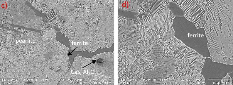
ECJSE 2021 (1) 117-132                                    Increasing Casting Speed in High Carbon and Micro Alloy …

1. Introduction

Developing world conditions and changing competition conditions lead companies to search for
new technology. One of the best conditions for competition is to produce products with high profit
margins and thus to make production profitable. The biggest supporter of profitability in production
is undoubtedly to increase production efficiency to the highest levels. The iron and steel industry is
a constantly developing sector. As of 2019, the world's total steel production amounted to 1.869
billion tons. Steel production increased by 3.4% in 2019 [1]. In continuous billet casting production
in iron and steel facilities, some studies were conducted in previous periods, considering the
optimization of process parameters and quality requirements. [2,3,4]. However, improvement study
of billet casting speed of high carbon and micro-alloyed DIN EN ISO 16120-2: 2011-C66D quality
steel, which is also referred to as carbon steels suitable for micro-alloyed high strength wire-spring-
rope manufacturing, was not encountered in previous periods. Continuous billet casting process
studies in other subjects within the scope of this study are given below.

In the study by C. Li, B.G. Thomas [5], titled as “Maximum casting speed for continuous cast steel
billets based on sub-mold bulging computation”, a computational study has been performed in 120,
175 and 220 mm square sizes in order to determine the maximum casting speed based on sub-mold
swelling and corner crack defects [6, 7]. S. Semplici, R. Karan, C. Mapelli [8] conducted a study on
mold corner design for high speed casting, which is titled as “Diamold design of corners in billet
high speed continuous casting” [9, 10]. In the study by Xiao, C., et al. [11] , which is titled as
“Control of macrosegregation behavior by applying final electromagnetic stirring for continuously
cast high carbon steel billet”, it has been stated that the solidification and segregation will be the
optimum value with the final electromagnetic mixer (F-EMS) at a casting speed of 1.65
meters/minute in 0.77% carbon SWRH77B quality steel with 360-ampere current/12 hertz
frequency [12, 13, 14].

In the study of Su, et al. [15], which is titled as “Heat transfer and central segregation of
continuously cast high carbon steel billet”, it has been studied that the optimization of the secondary
cooling with the billet surface temperature value and the casting of the center segregation with F-
EMS at a speed of 1.7 meters/minute may be appropriate in 160x10 mm size 0.81% carbon
SWRH82B quality steel [16, 17]. In the study by Luo, et al. [18], which is titled as “Numerical
Simulation and Experimental Study of F-EMS for Continuously Cast Billet of High Carbon Steel”,
it has been studied with Ansys and CFX software that center segregation can be at optimum with
380-ampere current/6 hertz frequency value of F-EMS value at a casting speed of 1.9 meters/minute
in 160x160 size [19, 20]. In the study by Mortan, et al. [21], which is titled as “Next Steps in High-
Speed Billet Casting at Ege Celik (Aliaga, Turkey)”, the speed increase of 6.2 meters/minute in
130x130 mm cross-section in steels up to 0.19% carbon with equipment changes was examined. In
the study by scientists Cobelli, et al. [22], which is titled as “Fast Casting of 150 sq billets-boost of
productivity”, the sub-mold additional role, the design changes made in the mold water grooves of
the chrome-plated mold and the design changes in the in-mold transition grooves as well as the high
casting speed of 5.6 meters/minute were examined in the production of 150x150 size in 0.32%
carbon steel [23].

As can be seen from previous studies, higher casting speeds in different grades, optimization of
equipment parameters and quality requirements have been studied in billet casting production [24,
25]. However, improvement study of billet casting speed of high carbon and micro-alloyed DIN EN
ISO 16120-2: 2011-C66D quality steel, which is also referred to as carbon steels suitable for micro-
alloyed high strength wire-spring-rope manufacturing, was not encountered in previous periods. In
this study, the speed increase in the continuous billet casting process has been tried to be achieved
without deteriorate the meallographic internal structure, physical properties and quality of the steel
billet produced and by keeping the product defects specified in the standards to a minimum. It is

                                                  118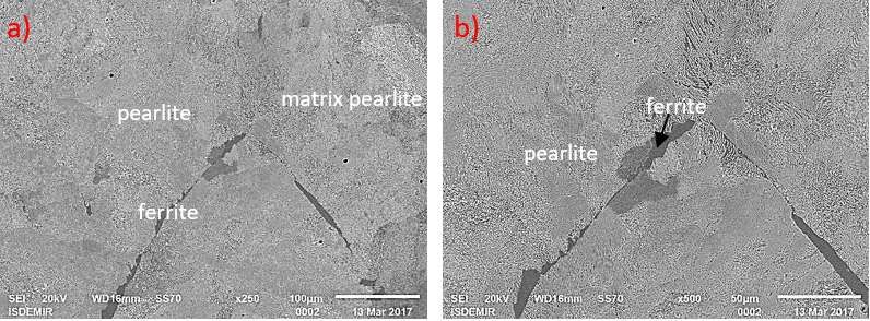
Bölükbaşı, Ö.S, Kızılay, V.                                                             ECJSE 2021 (1) 117-132

aimed to increase the production resulting from the increase in speed by considering the quality
requirements.

2. Material and Method

2.1. Raw Materials Used in the Study
In continuous casting processes, it is generally produced in two ways, horizontal and vertical. The
horizontal casting style has many superior aspects compared to vertical casting styles. Therefore,
horizontal casting type is preferred within the bounds of possibility. It is possible to cast all non-
ferrous metals horizontally [26, 27]. Types of continuous casting plant can be grouped under the
headings of a vertical, vertical twisted, circular arc and oval curved continuous casting machines.
Continuous casting methods are shown in Figure 1.

                                   Figure 1. Continuous casting methods [29].

The main raw material used in the study is high carbon and micro-alloyed DIN EN ISO 16120-2:
2011-C66D quality steel. The study was performed by a closed casting process, the material used is
the final product of the continuous billet casting machine of an integrated (where coke, sinter, blast
furnace, steelwork, continuous casting, rolling mill facilities coexist) iron steel facility. The steel
billet used in the tests is the highest tonnage steel quality produced by the closed casting process at
the aforementioned facility. High carbon and micro-alloyed DIN EN ISO 16120-2: 2011-C66D
quality steel, which has added value under competitive conditions, is used in the production of high
strength wire-spring-rope.

  Table 1. Chemical analysis table of the standard used for billet steel (DIN EN ISO 16120-2: 2011-C66D)

               C%        Mn%     P%       S%      Si%    Al%    Ti%    Nb%      V%        B%
               0.65       0.60   0.012   0.012    0.20   0.010 0.010   0.008    0.010   0.0045
               Ni%       Cu%     Cr%     N ppm   Mo%     Sn%    Pb%    Mn/S     C%        Ca
               0.08       0.10   0.080    90     0.015   0.015 0.010     35       -        -

Macro samples of 130x130x30 mm were taken with an oxy gas cutting system. Macro samples
marked with the casting number and channel information have been prepared to make them suitable
for examination in a laboratory environment.

The test samples were milled on the milling machine to smooth their surfaces. In each casting
produced, one macro sample was taken from each channel in the last 60-80 tons of the melting pot
for testing. Cutting the samples at a suitable size is presented in Figure 2-a and the numbering of the

                                                      119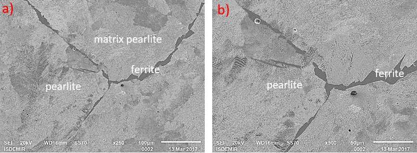
ECJSE 2021 (1) 117-132                                          Increasing Casting Speed in High Carbon and Micro Alloy …

cut materials is presented in Figure 2-b. In the experiment, a total of 18 samples were selected in the
three aforementioned castings and 10 of them were found suitable for examination.

                         a)                                b)

               Figure 2. a) Macro sample cutting process b) Casting channel numbering

                                       Figure 3. Milling processing machine

The milling processing machine we used in this study is presented in Figure 3. Samples, whose
surface treatment has been completed by milling, are placed in the macro sample manipulation
basket for etching.

 a)                                      b)                                     c)

                          Figure 4. a) Acid tank b) Rinsing tank c) Surface cleaning

A suitable mixture was prepared with 40% HCl (38%) and 60% water for etching of the samples
placed in the macro sample manipulation basket. The prepared mixture samples were kept in acid
tanks that are large enough for etching, and they were etched for 50 minutes. Most of the
metallurgical examination is made after etching the polished surfaces with a suitable chemical
solution. The surface of the macro sample to be checked may be contaminated by external
structures such as grease or oil, and there may also be stains and discoloration due to rust. The
surface to be checked underwent etching bath and the existing acid, rust or oxide layer was removed
without damaging the metal. After the etching process was completed, the samples were rinsed in
an alkaline solution for 15-30 seconds. Acid rinsing and changing apparatus of macro sample

                                                     120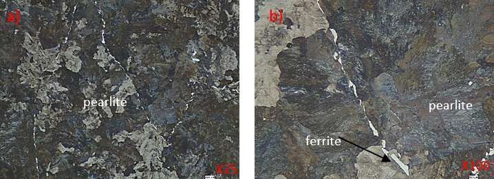
Bölükbaşı, Ö.S, Kızılay, V.                                                        ECJSE 2021 (1) 117-132

manipulation basket was used for manipulation in etching and rinsing processes. After rinsing,
surfaces were cleaned with water and alcohol.

                              a)                       b)

Figure 5-a) Macro samples to be examined, b) Macro examination and photographing of samples

The macro samples to be examined is presented in Figure 5-a. As seen in Figure 5-b, macro sample
examination and photographing have been done in a machinery with appropriate lighting. SEM-
EDS and optical microscope images were taken and examined after sanding and polishing to
examine the micro structures of billet steel samples. Jeol JMS-6510 SEM and Nikon Epiphot 200
optical microscope were used in the image examinations on the samples. In addition, XRD and
Autoquan analysis studies were performed on samples. Preliminary evaluation of defects and other
parameters in macro samples was performed by taking into consideration ASTM E381 (Standard
method of macro etch testing steel bars, billets, blooms, and forgings1) standard [28] and also the
Billet Internal Structure Defects section of the "Long Product Defect Catalog" prepared by the iron
and steel factories where the experimental study was conducted.

2.2 Method

This study aims to increase the continuous casting production rate by optimizing the operating
parameters and to investigate the effect of the steel material produced on the quality parameters.
This study also aims to optimize the process parameters without decreasing the quality in the
production with 3.2 meters/minute casting speed of high carbon and micro-alloyed DIN EN ISO
16120-2: 2011-C66D quality steel produced at 2.8 meters/minute casting speed under current
operating conditions. The steel produced in this article has been investigated whether its mechanical
and physical structure is within the framework of quality standards in terms of macro and micro
examinations.

3. Research Results and Discussion

3.1 Experiment Data

The temperature of the liquid steel in the tundish (target value between 1510 and 1520 oC) was
measured. The casting speed, electromagnetic stirring in mold (M-EMS) and specific water volume
values were changed, and 10 different test studies were performed in three different castings with
approximately 600 tons of liquid steel. Experimental groups and test studies are presented in Table
2. The first group is experimental study 1, 2 and 3, and the second group is experimental study
4,5,6,7,8 and the third group study is 9 and 10.

In the first group test study, it was taken as a basis that the speed could be increased and the
optimization of the M-EMS value. In the first group experimental study, the casting speed of 2.8
meters/minute was increased to 2.9 meters/minute and 3.0 meters/minute. The optimization of the
M-EMS value was performed at a casting speed of 2.8 meters/minute. In the second group
experimental study, it was taken as a basis that the speed can be increased to 3.2 meters/minute after
the optimization of the M-EMS value and that the speed can also be increased in a different casting.
                                                 121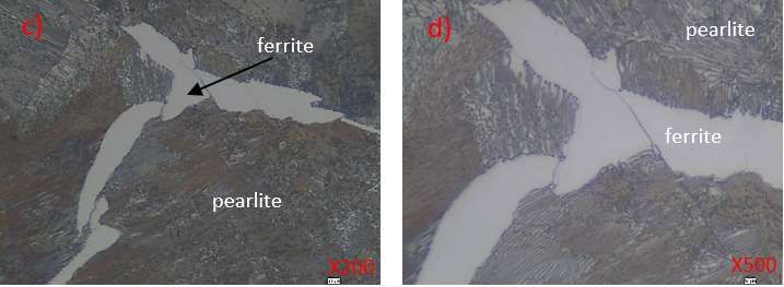
ECJSE 2021 (1) 117-132                                          Increasing Casting Speed in High Carbon and Micro Alloy …

Depending on the suitability of the second group experimental study quality results, a third group
experimental study was performed in another casting. In the third group experimental study, it was
taken as a basis that solidified shell sufficiency is provided to prevent shell ruptures that may occur
due to ferrostatic pressure in the liquid steel with the increase of the specific secondary cooling
water volume after optimizing the M-EMS value and increasing the speed to 3.2 meters/minute and
that speed can also be increased for a different casting.

                                Table 2. Parameters applied in experiments
                                  M-EMS                 Secondary Cooling                Casting Speed
                            (current/frequency)          (liter/kilogram)               (meter/minute)
    Test           Test    Routine         Test        Routine          Test         Routine         Test
   Group           No     Application   Application   Application    Application    Application   Application
      1              1      360/5         400/5          0.95            0.95           2.8           2.8
                     2      360/5         400/5          0.95            0.95           2.8           2.9
                     3      360/5         400/5          0.95            0.95           2.8           3.0
      2              4      360/5         400/5          0.95            0.95           2.8           2.8
                     5      360/5         400/5          0.95            0.95           2.8           2.9
                     6      360/5         400/5          0.95            0.95           2.8           3.0
                     7      360/5         400/5          0.95            0.95           2.8           3.1
                     8      360/5         400/5          0.95            0.95           2.8           3.2
      3              9      360/5         400/5          0.95            0.95           2.8           3.2
                    10      360/5         400/5          0.95            1.27           2.8           3.2

While evaluating the experiments, the data of different operational parameters were used by
considering the quality requirements. The experimental study in three different castings was
evaluated in three groups. The parameters applied in the first experiment group 1, 2 and 3 test study
shown in Table 2. In summary, in the first group first casting experiment, the speed can be
increased and the optimization of M-EMS value has been taken as a basis.

Depending on the suitability of the first group experimental study quality results, second group
experimental study was conducted in another casting. The parameters applied to the tests 4, 5, 6, 7
and 8 in the second group of steel billets in a different casting are shown in Table 2.

In summary, in the second group, second casting experimental study, it was taken as a basis that the
speed could be increased to 3.2 meters/minute after optimization of the M-EMS value and also the
speed could be increased in a different casting. Depending on the suitability of the second group
experimental study quality results, a third group experimental study was performed in another
casting. Application parameters given in Table 2, the third experimental groups 9 and 10 which
effect the process of the test work are summarized below.

In summary, in the third group experimental study, it was taken as a basis that solidified shell
sufficiency is provided to prevent shell ruptures that may occur due to ferrostatic pressure in the
liquid steel with the specific increase of the secondary cooling water volume after optimizing the
M-EMS value and increasing the speed to 3.2 meters/minute and that speed can also be increased
for a different casting.

In the tests applied with the application of 0.95 liter/kilogram specific water volume, the secondary
cooling zone applied from experiment 1 to experiment 9, it showed a distribution of 0.26
liter/minute in zone 1, 0.30 liter/minute in zone 2a, 0.16 liter/minute in zone 2b, 0.11 liter/minute in
zone 3a, 0.12 liter/minute in zone 3b throughout the line. In the test study performed by increasing

                                                      122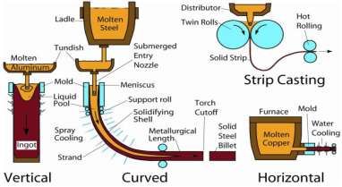
Bölükbaşı, Ö.S, Kızılay, V.                                                                                  ECJSE 2021 (1) 117-132

the secondary cooling zone-specific water volume to 1.27 liter/kilogram in Experiment 10, it
showed a distribution of 0.36 liter/minute in zone 1, 0.38 liter/minute in zone 2a, 0.20 liter/minute
in zone 2b, 0.11 liter/minute in zone 3a, 0.12 liter/minute in zone 3b, 0.11 liter/minute in zone 3c
throughout the line. The distribution of the specific water volume applied in the tests in the
continuous casting secondary cooling zone by region is shown together in Figure 6.

                                    0,40
                                                            0,38
                                           0,36
                                    0,30
                   liter/kilogram

                                                     0,30
                                            0,26                      0,20
                                    0,20
                                                                                             0,12
                                                                   0,16        0,11                         0,11
                                    0,10                                                    0,12
                                                                             0,11
                                                     0.95 liter/kilogram            1.27 liter/kilogram
                                    0,00
                                            zone 1   zone 2a       zone 2b   zone 3a       zone 3b        zone 3c
        Figure 6. Specific water volume variation in secondary cooling zones of billet samples

It is aimed to ensure the sufficiency of solidified hardening shell to prevent shear ruptures that may
occur due to ferrostatic pressure in the liquid steel with the increase in specific secondary cooling
water volume. While cutting the billet material, it is desired that solidification is completed and
there is no liquid steel in the billet. Otherwise, it may cause very serious occupational health and
safety risks in addition to serious production losses. Therefore, attention has been paid to
determining the secondary cooling process parameters to ensure proper solidification.

3.2. Macro Examination at Different Casting Speeds

3.2.1 First Group Experimental Tests

Test studies conducted in the first group include the experiments 1, 2 and 3 shown in Table 2. In the
test studies, the M-EMS 360 amp current/5 hertz frequency value that was routinely studied without
changing the existing operating parameters was changed to 400 amp current/5 hertz frequency for
each trial (Table 2). In the first type experiment, the casting speed was not changed and it was
performed at 2.8 meters/minute, which is traditionally applied by the enterprise (macro sample
image Figure 7-a). In the 2nd and 3rd test studies, the tests were carried out by increasing the
operating routine 360 current/5 hertz value to 400 ampere current/5 hertz frequency for each test
without making changes in the existing operating parameters. The casting speed was increased from
the speed of 2.8 meters/minute for each test to 2.9 and 3.0 meters/minute, respectively (macro
sample images Figure 7-b and c).

         a)                                           b)                                     c)

Figure 7. Steel billet macro sample 1st group experimental test pictures a) No: 1, Casting speed: 2.8
         m/min.; b) No: 2, Casting speed: 2.9 m/min.; c) No: 3, Casting speed: 3.0 m/min.
                                                                    123
ECJSE 2021 (1) 117-132 Increasing Casting Speed in High Carbon and Micro Alloy …
Continuous casting quality standards were ensured in group 1 experimental tests. As can be seen in
Figure 7-a, b, c), center segregation, center withdrawal cavity, center star crack, gas gap, inclusion
band, halfway crack, diagonal crack defects were at an acceptable level based on the defects in the
long product defect catalogue in group 1 macro sample test studies. The segregation structure
observed outside the central structure is related to steel cleaning and is at an acceptable level. Since
the diagonal differences of the shape of the billet and the non-uniform structure near the edge meet
the dimensional needs, no inconvenience has been observed. After confirming that the first group
experimental test results were within the acceptance criteria, the second group experimental studies
were started.
3.2.2 Second Group Experimental Tests
The studies in the second group include the tests carried out in the second casting, which covers the
tests numbered 4,5,6,7,8 shown in Table 2. In the 4th experiment, the M-EMS 360-ampere current/5
hertz frequency value, which was routinely produced without changing the existing operating
parameters, was increased to 400-ampere current/5 hertz. The test was performed on a different
casting without changing the traditionally applied 2.8 meters/minute casting speed. As seen in Table
2, the operating routine of M-EMS 360-ampere current/5 hertz frequency value was increased to
400 ampere current/5 hertz frequency for each experiment in the experiments 5, 6, 7 and 8,
respectively. In addition, the tests were performed by increasing the casting speed of 2.8
meters/minute, which is traditionally applied in continuous casting, to 2.9 meters/minute, 3.0
meters/minute, 3.1 meters/minute and 3.2 meters/minute for each test, respectively. Macro images
of steel billets produced at each production speed in the second group are presented in Figure 8-a, b,
c, d, e respectively.
a) b) c)
d) e)
Figure 8. Macro sample pictures of second group experimental tests of a steel billet samples a) No:
4, Casting speed: 2.8 m/min., b) No: 5, Casting speed: 2.9 m/min., c) No: 6, Casting speed: 3.0
m/min., d) No: 7 , Casting speed: 3.1 m/min. e) No: 8, Casting speed: 3.2 m/min.
124Bölükbaşı, Ö.S, Kızılay, V. ECJSE 2021 (1) 117-132
During the 2nd group test studies, the desired quality for continuous casting has been reached. As
can be seen in the macro sample picture in Figure 8, it is seen that the defects in the manufactured
products are within acceptable limits according to the long product defect catalogue. After the
second group tests were completed, the third group tests were started.
3.2.3 Third Group Experimental Tests
The studies in the third group involve the studies including the 9th and 10th experiments shown in
Table 2. In the third group tests, both tests were performed by increasing the M-EMS 360 amp
current/5 hertz frequency value in the routine operation to 400 amp current/5 hertz frequency.
Secondary cooling, 0.95 liter/kilogram specific water volume was kept constant in test no. 9 and the
casting speed was increased from 2.8 meters/minute, which is the operating routine, to 3.2
meters/minute. In experiment 10, the secondary cooling specific water volume was increased from
0.95 liter/kilogram to 1.27 liter/kilogram and the casting speed was 3.2 meters/minute.
a) b)
Figure 9. Macro sample pictures of third group experimental tests a) No: 9, volume of water
0.95 litre/kilogram, Casting speed: 3.2 m/min, b) No: 10, volume of water 1.27 litre/kilogram,
Casting speed: 3.2 m/min.
In the continuous casting billet production experiments, no significant difference was observed
between the casting speed of 2.8 meters/minute and the casting speed of 3.2 meters/minute that
would negatively affect the billet quality in the phase structures formed within the steel body
(Figure 9-a and b). Phase structures occurring during production may differ according to the
working conditions and quality demands of the billet steel to be produced in the subsequent rolling
production process.
3.3. Optical Microscope Examinations on the Billet Sample
In this study, samples for microscopic examinations and image analysis were prepared using
Mecapress II specimen mounting press device and Phenolic Bakelite Powder. Metkon Digiset-2V
device was used for grinding the sample. SiC foil emery was used with varying grit sizes namely
respectively 180, 320, 600, 1200 and 2500 during the grinding process. After the grinding process,
Struers Tegramin 25 polishing device was used to remove the sanding scratches on the surface and
make the sample ready for optical examination. The polishing steps are 6μ, 3μ and 1μ and were
carried out by using Polycrystalline Diamond suspension.
In the research, optical microscope examinations were made on the specimens produced in
continuous castings using Nikon Epiphot 200 model microscope and X25, X100, X200, X500
magnifications.
In the study in the continuous casting facility, steel billets produced with a speed of 2.8 m/min, as
seen in Figure 10, elongated grains were seen from the edge to the center at X25 magnification with
125ECJSE 2021 (1) 117-132 Increasing Casting Speed in High Carbon and Micro Alloy …
an optical microscope. Ferrite structures that are formed at the grain boundary have been
determined.
Figure 10. Optical microscope image of a steel billet sample produced with a casting speed of 2.8 m/min.
It has been seen that almost all of the building is perlite. In the layer defined as the mixed zone,
there are impurities with lower oxidation potential [30]. Ferrite grains are rarely encountered
throughout the building. It has been seen that the steel billet sample matrix is mostly composed of
perlite structure. In Figure 10-b, perlite grains appeared at X100 magnification.
Figure 11. Optical microscope image of steel sample produced with a casting speed of 3.2 m/min.
126Bölükbaşı, Ö.S, Kızılay, V. ECJSE 2021 (1) 117-132
In Figure 10-c, it has been seen that perlite grains are formed more clearly at X200 magnification.
Lamellas in perlite grains began to appear. Perlite grains have been clearly seen at X500
magnification in Figure 10-d. It has been observed that the perlite grains and lamellae are larger in
size.
As can be seen in Figure 11, it has been determined that the main structure of the steel billet matrix
consists of perlite and there is a ferrite phase between the grain boundaries. As can be seen in
Figure 11-a, longitudinally solidified grains has been detected at X25 magnification. Ferrite
structures have been detected between the grain boundaries. It has been determined that the matrix
texture of the steel billet sample consists of the pearlite phase. In the examinations performed with
X100 magnification in Figure 11-b, it has been seen that pearlite phase grains emerged
significantly. In the examination performed with X200 magnification in Figure 11-c, it has been
seen that Perlite grains and ferrite structure look better. Lamellae within the perlite grains have
started to appear more distinct. However, some ferrite can be lined along the high temperature
rolling direction during production [31]. In Figure 11- d, perlite grains and lamellae intertwined
with each other are clearly evident at X500 magnification.
3.4 SEM and EDS Examinations on Billet Sample
In the article study, SEM image and elution analysis were performed on slab samples produced in
continuous castings on X250, X500, X1000, X2500 magnifications using Jeol JSM-6510 scanning
electron microscope (SEM) with a resolution of 30 kV 3.0 nm. In element analysis, Oxford X
MaxN50 detector with 124 eV resolution and EDS unit with inca and aztec software was used.
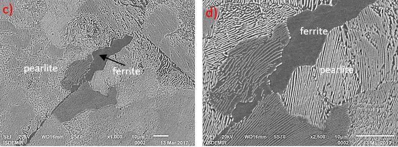
Figure 12. SEM image of billet steels produced with a casting speed of 2.8 m/min.
As seen in figure 12, structures similar to optical microscope images have been detected in SEM
image on the samples taken in the production of a steel billet material with a speed of 2.8 m/min. In
127ECJSE 2021 (1) 117-132 Increasing Casting Speed in High Carbon and Micro Alloy …
Figure 12-a, it has been determined that almost all of the structure is perlite and there are ferrite
structures at the grain boundary.
Figure 13. SEM image of billet steels produced with a casting speed of 3.2 m/min.
As seen in Figure 13, it has been determined that there were ferrite structures between the grain
boundaries where the matrix consists of perlite, as expected in Figure 13, on the samples taken in
the production of a steel billet material with a speed of 3.2 m/min. As the magnification rate
increases, it can be seen in Figures 13-b, c and d that the perlite grains appear more clearly and the
lamellas are more prominent. As examined in the optical microscope image, it was seen that most of
the billet steel phase morphology was formed in the perlite structure.
Figure 14. EDS image of billet steels produced with a casting speed of 2.8 m/min.
128Bölükbaşı, Ö.S, Kızılay, V. ECJSE 2021 (1) 117-132
In EDS examinations on steel billet samples, Fe and C structures were determined in the analyses
performed on steel billet samples produced at 2.8 m/min and 3.2 m/min casting speeds (indicated in
Figure 14 and 15).
Figure 15. EDS image of billet steels produced with a casting speed of 3.2 m/min.
3.5 XRD and Autoquan Analysis Examinations on Billet Sample
In this study, the Rigaku XRD, Thermo-ARL XRF and Nikon optical microscope were used.
a) b)
Figure 16. XRD analysis of a steel billet sample taken at a) 2.8 m/min and b) 3.2 m/min casting
speeds
As can be seen in Figure 16-a), when we look at the phase structure with the XRD device; a high
intensity (peak) value of 204.721 at 53o at 2 theta (θ) angle was obtained in steels produced with a
speed of 2.8 m/min. This situation can be explained by the slower cooling of the produced billet and
the formation of crystal structures under more favourable conditions. As can be seen in Figure 16-b,
when we look at the phase structure with the XRD; a lower intensity (peak) value was obtained as
119.989 at 53o at 2 theta (θ) angle in steels produced with 3.2 m/min speed. This can be explained
by the fact that the billet has cooled down faster and the crystal structures are not well-formed.
a) b)
Figure 17. Autoquan program result for a) 2.8 m/min and b) 3.2 m/min casting speed of a steel billet sample
129ECJSE 2021 (1) 117-132 Increasing Casting Speed in High Carbon and Micro Alloy …
As can be seen in Figure 17-a and b), it was observed that the phase structure was 100% iron alpha
phase structure at 2.8 m/min and 3.2 m/min casting speeds in the examination we made on the
sample with the Autoquan program with the help of Rietveld method.
4. Conclusion and Recommendations
When the data obtained from the experiments performed for steel billet production at different
speeds and the comparisons of these results are examined, it was seen that the speed of billet casting
from 2.8 m / min to 3.2 m / min. Especially; it has been observed that an increase in production can
be achieved by determining the casting speed, M-EMS and secondary cooling parameters by
considering the quality expectations. It has been observed that it is possible to increase the speed of
billet production with the prerequisite of meeting the quality needs in the case of liquid steel
analysis and temperature values, equipment and operating parameters and operational operating
conditions.
Considering the quality needs and production continuity, the production of 200 tons of liquid steel
at a casting speed of 2.8 meters / minute in a continuous casting machine with 130x130 mm size
and 6 channel casting is calculated as 133 tons / hour in theory. With the same process conditions,
the casting speed of 3.2 meters / minute can be reached, resulting in a production amount of 152
tons / hour. The hourly production increase of 14% in continuous billet casting production provides
a significant added value in market conditions and cost-oriented approaches.
References
[1]. https://tr.steelorbis.com/celik-fiyatlari/celik-istatistikleri, Date of access: 10.05.2020
[2]. Chow, C., “The effects of high speed casting on the mould heat transfer, billet solidification,
and mould taper design of continuously cast steel billets”, Master’s Thesis, The University of
Waterloo, Ontario-Canada, 2001, 25-28.
[3]. Li, C., Thomas, B. G., Ojeda, C., “Ideal Taper Prediction for High Speed Billet Casting. Part
I”, Continuous Casting Consortium, University of Illinois at Urbana-Champaign, 2002, 5-7.
[4]. Chatterjee, S., Li, D., Chattopadhyay, K., “Modeling of liquid steel/slag/argon gas multiphase
flow during Tundish open eye formation in a two-strand Tundish”. Metallurgical and
Materials Transactions B, 2018, 49(2), 756-766.
[5]. Li C., Thomas B.G., “Maximum Casting Speed for Continuous Cast Steel Billets Based on
Sub-Mold Bulging Computation”, 85th Steelmaking Conf. Proc., ISS, Warrendale, PA, (held
in Nashville, TN, March 10-13, 2002),109-130, 2002
[6]. Kittaka, S., Uehara, M., Sato, T., Higashi, H., “High speed casting mold for billet caster (NS
hyper mold)”, Nippon Steel Technical Report (Japan), 2000, 82, 65-70.
[7]. Thomas, B. G., “Continuous Casting of Steel”, Department of Mechanical and Industrial
Engineering University of Illinois at Urbana-Champaign 1206 West Green Street Urbana, IL
61801, U.S.A., 2001, Chapter, 15, 499-540.
[8]. Semplici, S., Karan, R., Mapelli, C., “Diamold design of corners in billet high speed
continuous casting”, la metallurgia italiana, 2005. 58-90.
[9]. Haiqi, Y. U., and Z. H. U. Miaoyong. "Effect of electromagnetic stirring in mold on the
macroscopic quality of high carbon steel billet." Acta Metallurgica Sinica (English Letters)
22.6, 2009, 461-467
[10]. Wu, Chenhui, Cheng Ji, and Miaoyong Zhu. "Influence of differential roll rotation speed on
evolution of internal porosity in continuous casting bloom during heavy reduction." Journal of
Materials Processing Technology 271 (2019): 651-659.
130Bölükbaşı, Ö.S, Kızılay, V. ECJSE 2021 (1) 117-132
[11]. Xiao, C., Zhang, J. M., Luo, Y. Z., Wei, X. D., Wu, L., Wang, S. X., “Control of macro
segregation behaviour by applying final electromagnetic stirring for continuously cast high
carbon steel billet”. Journal of Iron and Steel Research International, 2013, 20(11), 13-20.
[12]. Sengupta, J., Thomas, B. G., Wells, M. A., “Understanding the role water-cooling plays
during continuous casting of steel and aluminum alloys”. In Conference Proceedings of
M&ST, 2004, 179-193.
[13]. Wu, C., Ji, C., Zhu, M., “Closure of internal porosity in continuous casting bloom during
heavy reduction process”. Metallurgical and Materials Transactions B, 2019, 50(6), 2867-
2883.
[14]. Thomas, B. G., “Review on modelling and simulation of continuous casting”. Steel research
international, 2018, 89(1), 1700312.
[15]. Su, W., Wang, W. L., Luo, S., Jiang, D. B., Zhu, M. Y., “Heat transfer and central segregation
of continuously cast high carbon steel billet”. Journal of Iron and Steel Research International,
2014, 21(6), 565-574.
[16]. Atalay, G., “Solidification and Cooling Investigation in Continuous Casting”, Yıldız
Technical University, Master's Thesis, 2008.
[17]. Maurya, A., Jha, P. K., Influence of electromagnetic stirrer position on fluid flow and
solidification in continuous casting mold. Applied Mathematical Modelling, 2017, 48, 736-
748.
[18]. Luo, S., Piao, F. Y., Jiang, D. B., Wang, W. L., Zhu, M. Y., “Numerical simulation and
experimental study of F-EMS for continuously cast billet of high carbon steel”. Journal of
Iron and Steel Research, International, 2014, 21(1), 51-55.
[19]. Akpınar, M., Minimization of Banded Structure In Sprıng Steels By The Optımızatıon Of
Continuous Casting Machine Parameters (Doctoral Dissertation, Middle East Technical
University), 2019.
[20]. Yu, S., Long, M., Chen, D., Fan, H., Yu, H., Duan, H, Liu, T, “Effect of the mold corner
structure on the friction behavior in slab continuous casting molds”. Journal of Materials
Processing Technology, 2019, 270, 157-167.
[21]. Mortan, J., Kapaj, N., Sezer H., “Next Steps in High-Speed Billet Casting at Ege Celik
(Aliaga, Turkey)” Metec 2nd Estad, Düsseldorf, 15-19 June 2015.
[22]. Cobelli, P., Grundy, A.N., Feldhaus S., Hsu,Y.C., Lo C.H., Lin, C.H., “Fast Casting of 150 sq
billets-boost of productivity” Metec 2nd Estad, Düsseldorf 15-19 June 2015.
[23]. Roy, S., Singh, R. K., Keshari, K. K., Pradhan, N., Kumar, M., Gupta, A, Mishra, B.,
“Reduction in Surface Defect in Continuous Cast Slab through Intervention in Process
Parameters”. In Materials Science Forum, Trans Tech Publications Ltd., 2020, Vol. 978, 91-
96.
[24]. Villoria, R., Stafforte, H., Sparapani, O., Madias, J., Dziuba, M., “High speed continuous
casting of low carbon steel billets”. In Seventy Ninth Conference of the Steelmaking Division
of the Iron and Steel Society, 1996, 315-319.
[25]. Mazumdar, D., “Review, Analysis, and Modeling of Continuous Casting Tundish
Systems”. Steel Research International, 2019, 90(4), 1800279.
[26]. Concast-a, Continuous Casting Machine 6-Strand Billet Caster, “Functional Description”,
2003.
[27]. Concast-b, Continuous Casting Machine 6-Strand Billet Caster, “Metallurgical, Operating and
Safety Manual”, 2003.
[28]. ASTM E381, Standard Method of Macroetch Testing Steel Bars, Billets, Blooms, and
Forgings, Designation: E381 − 01 (Reapproved 2012).
131ECJSE 2021 (1) 117-132 Increasing Casting Speed in High Carbon and Micro Alloy …
[29]. Thomas, B. G., Continuous Casting (metallurgy). Yearbook of Science and Technology,
2004, 1-6.
[30]. Akkaş, M., Çulha, O., Investigation of the Reasons for the Occurrence of Iron Oxides in Alloy
Steel Profiles Produced by Hot Rolling with Different Colors than Normal. (in Turkish), El-
Cezeri Journal of Science and Engineering, 2020, 7(3):1220-1230.
[31]. Tümer, M., Kerimak, M. Z., Effect of Different Additional Metals on Toughness and
Microstructural Properties in the Joining of Nickel Based Super Alloy Inconel 625 and AISI
304L Stainless Steel Material Pair (in Turkish), El-Cezeri Journal of Science and Engineering,
2017, (1):118-119.
132You can also read