Interchange Comm Control Module, MX4-R2 Series - Installation and Operations Manual - FW ...
←
→
Page content transcription
If your browser does not render page correctly, please read the page content below
Interchange™ Comm Control Module,
           MX4-R2 Series

     Installation and Operations Manual

                                          00-02-1024
                                          2021-10-04
                                          Section 50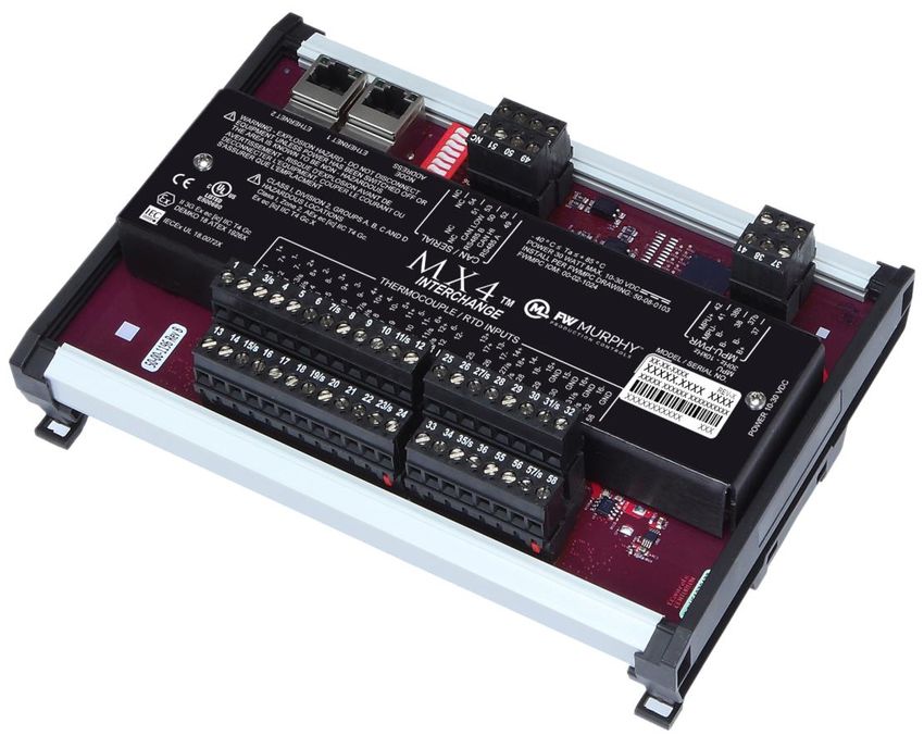
BEFORE BEGINNING INSTALLATION OF THIS FW MURPHY
PRODUCT:
Please read the following information before installing the MX4-R2
Module. This installation information is intended for MX4-R2 Module
only.
Visually inspect the product for any damage during shipping.
Before proceeding please visit our website and review our support
documentation including Wiring the Murphy Way
www.fwmurphy.com/uploaded/WIR_Murphy_Way.pdf
Disconnect all power and be sure machine is inoperative before
beginning installation.
Installation is to be done only by a qualified technician of the
Responsible Body.
Observe all Warnings and Cautions at each section in these
instructions.
Device shall be wired in accordance with NEC, CEC or other local
code, as applicable.
Please contact FW Murphy immediately if you have any questions.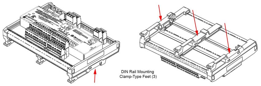
For Class I, Division 2:

THIS EQUIPMENT IS AN OPEN-TYPE DEVICE AND IS MEANT TO BE INSTALLED IN AN
ENCLOSURE SUITABLE FOR THE ENVIRONMENT SUCH THAT THE EQUIPMENT IS
ONLY ACCESSIBLE WITH THE USE OF A TOOL.

THIS EQUIPMENT IS SUITABLE FOR USE IN CLASS I, DIVISION 2, GROUPS A, B, C
AND D OR NON-HAZARDOUS LOCATIONS ONLY.

WARNING – EXPLOSION HAZARD – DO NOT DISCONNECT EQUIPMENT UNLESS
POWER HAS BEEN REMOVED OR THE AREA IS KNOWN TO BE NON-HAZARDOUS.

WARNING – EXPLOSION HAZARD – DO NOT REPLACE BATTERIES UNLESS THE AREA
IS KNOWN TO BE FREE OF IGNITABLE CONCENTRATIONS.

TEMPERATURE CODE OF T4 FOR ALL MODELS.

PROVIDES NONINCENDIVE FIELD WIRING OUTPUTS/INPUTS WHEN WIRED
ACCORDING TO DRAWING 50-08-0103 (MX4-R2-X).

For AEX/EX Class I, Zone 2:

THE EQUIPMENT SHALL ONLY BE USED IN AN AREA OF POLLUTION DEGREE 2.

THE EQUIPMENT SHALL BE INSTALLED COMPLETELY WITHIN AN ENCLOSURE THAT
PROVIDES A MINIMUM INGRESS PROTECTION OF IP 54 IN ACCORDANCE WITH
UL60079-0 AND ONLY ACCESSIBLE BY THE USE OF A TOOL.

THE WIRE SIZE, TORQUE RATING OF 12-24 AWG, 0.37-0.44 ft. lbs.(0.4-0.5 Nm), AND
SUITABLE
SUPPLY WIRE TEMPERATURE RATING OF 97ºC MINIMUM SHALL BE PROVIDED FOR
THE INPUT POWER TERMINAL BLOCK.

ALL MARKING INFORMATION EXCEPT FOR SERIAL NUMBER/DATE CODES SHALL BE
REPEATED.

PROVIDES NONINCENDIVE FIELD WIRING OUTPUTS/INPUTS WHEN WIRED
ACCORDING TO DRAWING 50-08-0103 (MX4-R2-X).

SPECIAL CONDITIONS FOR USE IECEx/ATEX Zone 2:

THE EQUIPMENT SHALL ONLY BE USED IN AN AREA OF NOT MORE THAN POLLUTION
DEGREE 2, AS DEFINED IN IEC/EN 60664-1.

THE EQUIPMENT SHALL BE INSTALLED IN AN ENCLOSURE THAT PROVIDES A DEGREE
OF PROTECTION NOT LESS THAN IP 54 IN ACCORDANCE WITH IEC/EN 60079-0 AND
ONLY ACCESSIBLE BY THE USE OF A TOOL.
THIS PAGE INTENTIONALLY LEFT BLANK
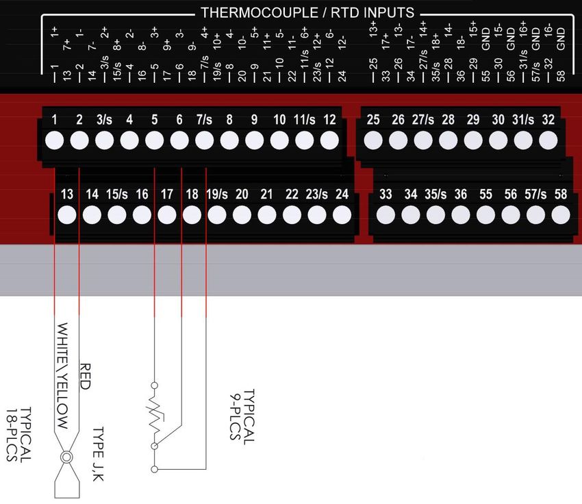
Table of Contents
FW Murphy Interchange Comm Control Module Series.......................................................1

      Accessories ..................................................................................................................1
      Specifications ...............................................................................................................1
Installation ...................................................................................................................................2

      Dimensions ..................................................................................................................2
      Install MX4-R2 Module .................................................................................................3
Wire Connections.......................................................................................................................4

      Wire Diagram — MX4-R2 Module ................................................................................4
      Entity Parameters .........................................................................................................5
      Thermocouple / RTD Inputs (Pins 1 – 36 and 55 – 58) ................................................8
      Power (Pins 37 – 38)....................................................................................................9
      Magnetic Pickup, MPU (Pins 41 – 42)........................................................................10
      RS485 (Pins 49 – 50) .................................................................................................11
      CAN (Pins 52 – 53) ....................................................................................................13
      DIP Switch Configuration ...........................................................................................14
      Ethernet......................................................................................................................15
Communications ......................................................................................................................17

      Modbus Holding Register Description ........................................................................18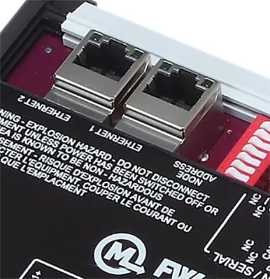
THIS PAGE INTENTIONALLY LEFT BLANK
FW Murphy Interchange Comm Control Module Series
The MX4-R2 expansion module provides temperature and frequency input capability to the
Centurion and future generations of FW Murphy Controllers using CAN proprietary
communication with enhanced diagnostics. A serial RS485 port and 2 Ethernet ports also
provide other communication methods to work with any Modbus RTU or Modbus TCP/IP client
device. MX4-R2 is backward compatible to MX4.
Accessories
MX4-R2 Plug Kit (00032656) Printed Terminal Plugs for MX4-R2 Expansion I/O Module
Specifications
Operating temperature: -40° to 185° F (-40° to 85° C)
Power input: 14.1 W max 10-30 VDC
All input options individually software selectable. No jumpers required.
18* Thermocouple temperature inputs:
o J or K Type Thermocouples
o 9* 3-wire 100Ω Pt RTD temperature inputs**
o Cold junction compensation
o Open, short DC-, short DC+ wire fault detection
One magnetic pickup input*/AC run signal
o 30 to 10 kHz
4 Communication ports:
o SERIAL RS485
Protocol: MODBUS RTU (server)
o CAN
Protocol: Proprietary for FW Murphy hardware
o Two Ethernet 10/100 (DLR):
Protocol: Modbus TCP/IP (server) / Ethernet/IP (CIP)
Third-party approvals for MX4-R2:
o Class I, Div 2, Grps A,B,C,D Haz. Loc. T4
o Class I, Zone 2, AEx ec [ic] IIC T4 Gc
Ex ec [ic] IIC T4 Gc X
o ATEX Zone 2:
II 3G Ex ec [ic] IIC T4 Gc
DEMKO 18 ATEX 1926X
-40°C ≤ Tamb ≤ +85°C
o IECEx Zone 2:
Ex ec [ic] IIC T4 Gc
IECEx UL 18.0072X
-40°C ≤ Tamb ≤ +85°C
* Non-incendive. (Digital Inputs, Analog Inputs and Temperature Inputs are intrinsically safe and non-incendive.
** RTD=Resistive Temperature Device, American RTD Standard, TCR 0.00392, units Ohms/Ohm / deg. between 0-100 C.
NOTE: For each channel that is selected as RTD, 2 thermocouple channels are used and no longer available as thermocouple
channels.
Section 50 00-02-1024
2021-10-04 -1-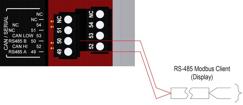
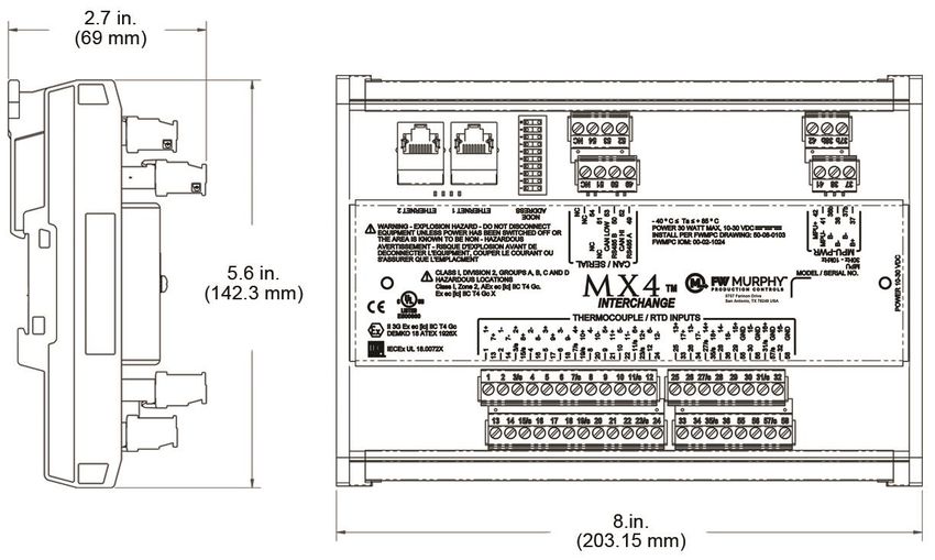
Installation
Dimensions

Section 50           00-02-1024
2021-10-04     -2-

Install MX4-R2 Module
The MX4-R2 must be mounted in an enclosure meeting the requirements of IP54 or greater
according to the intended use and environmental conditions in accordance with standard UL
and only accessible by use of a tool.
             NOTE: IP requirement is ONLY for North America and IECEx/ATEX
             Zones UL 60079, IEC/EN 60079-0.

   •   Operating Temperature -40° to 185° F (-40° C to +85° C)
   •   Pressure 80 kPa (0,8 bar) to 110 kPa (1,1 bar)
   •   Air with normal oxygen content, typically 21% v/v
   •   Temperature Class T4
   •   “ic”: intrinsic safety (for EPL Gc)
   •   Increased safety (for EPL Gc)

The MX4-R2 can be mounted vertically or horizontally on a standard DIN rail. Three clamp-
type feet along the bottom of the controller attach to the DIN rail; however, rail stops are
recommended to prevent sliding.

Section 50                                                                         00-02-1024
2021-10-04                                    -3-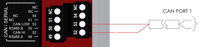
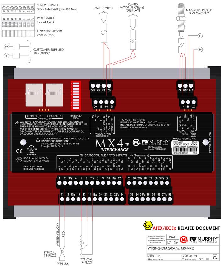
Wire Connections
Wire Diagram — MX4-R2 Module

Section 50                           00-02-1024
2021-10-04                     -4-
Entity Parameters
   1. The output current of this associated apparatus is limited by a resistor such that the output
      voltage-current plot is a straight line drawn between open-circuit voltage and short-circuit
      current. The Entity Concept allows interconnection of intrinsically safe apparatus with
      associated apparatus not specifically examined in combination as a system when the approved
      vales of Voc (or Uo) and Isc (or Io) for the associated apparatus are less than or equal to Vmax
      (Ui) and Imax (Ii) for the intrinsically safe apparatus. Capacitance and inductance of the field
      wiring from the intrinsically safe equipment to the associated apparatus shall be calculated and
      must be included in the system calculations. Cable capacitance, Ccable, plus intrinsically safe
      equipment capacitance, Ci must be less than the marked capacitance, Ca (or Co), shown on
      any associated apparatus used. The same applies for inductance (Lcable, Li and La or Lo,
      respectively). Where the cable capacitance and inductance per foot are not known, the following
      values shall be used: Ccable = 60 pF/ft., Lcable = 0.2 μH/ft.

                                                          Nonhazardous Location
                                                                   or
        Hazardous (Classified) Location                   Hazardous (Classified) Location
        Class I, Div 2 Grps A, B, C and D                 Class I, Div 2 Grps A, B, C and D
        Class I, Zone 2, Group IIC                        Class I, Zone 2, Group IIC
        IECEx/ATEX Zone 2, Group IIC                      IECEx/ATEX Zone 2, Group IIC

                         Ui ≥ Uo; Ii ≥ Io; Co ≥ Ci + Ccable; Lo ≥ Li + Lcable

   2. This associated apparatus may also be connected to non-incendive or simple apparatus as
      defined in Article 504.2 and installed and temperature classified in accordance with Article
      504.10 (B) of the National Electrical Code (ANSI/NFPA 70) or other local codes, as applicable.
      Examples of “simple apparatus” are general-purpose contact/switch, thermocouples and RTD.

Section 50                                                                               00-02-1024
2021-10-04                                      -5-
3. For Intrinsically Safe devices selected associated apparatus must be third-party listed as
providing intrinsically safe circuits for the application or have Voc or Vt not exceeding Vmax (or
Uo not exceeding Ui), Isc or It not exceeding Imax (or Io not exceeding Ii), and the Po of the
associated apparatus must be less than or equal to the Pmax or Pi of the intrinsically safe
equipment. Examples of “simple apparatus” are general-purpose contact/switch, thermocouples
and RTD.
4. Where multiple circuits extend from the same piece of associated apparatus, they must be
installed in separate cables or in one cable having suitable insulation. Refer to Article 504.30(B)
of the National Electrical Code (ANSI/NFPA 70) and Instrument Society of America
Recommended Practice ISA RP12.6 for installing intrinsically safe equipment.
5. Intrinsically safe circuits must be wired and separated in accordance with Article 504.20 of the
National Electrical Code (ANSI/NFPA 70) or other local codes, as applicable.
6. This associated apparatus has not been evaluated for use in combination with another
associated apparatus.
7. Control equipment must not use or generate more than 250 V rms or dc with respect to earth.
8. For installations in which both the Ci and Li of the intrinsically safe apparatus exceeds 1% of the
Co and Lo parameters of the associated apparatus (excluding the cable), then 50% of Co and
Lo parameters are applicable and shall not be exceeded.
WARNING:
EXPLOSION HAZARD - DO NOT DISCONNECT EQUIPMENT UNLESS POWER HAS BEEN
SWITCHED OFF OR THE AREA IS KNOWN TO BE NON-HAZARDOUS.
AVERTISSEMENT - RISQUE D'EXPLOSION - AVANT DE DECONNECTER L'EQUIPEMENT,
COUPER LE COURANT OU S'ASSURER QUE L'EMPLACEMENT EST DESIGNE NON
DANGEREUX.
Section 50 00-02-1024
2021-10-04 -6-Entity Parameters (continued)
Thermocouple/RTD Inputs (Per Pin) J1-J2
Designation Uo[V] Io[mA] Po[mW] Lo[H] Co[µF] Ui[V] Ii[mA] Pi[mW] Li[mH] Ci[uF]
Pins
2, 4, 6, 8, 10, 12, 14, 4.4 1.0 4.4 80 999.9 30 17.0 - 0 0.1
16, 18, 20, 22, 24, 26,
28, 30, 34, 36,
Pins
1, 3/s, 5, 7/s, 9, 11/s, 4.4 1.0 4.4 80 995.1 30 17.0 - 0.022 4.9
13, 15, 17, 19/s, 21,
23/s, 25, 27/s, 29,
31/s, 32, 33, 35/s
J2
Pin Thermocouple/RTD Inputs Ground
55, 56, 57, 58
RS485/CAN
Designation Uo[V] Io[mA] Po[mW] Lo[mH] Co[uF] Ui[V] Ii[mA] Pi[mW] Li[mH] Ci[uF] Ci[pF]
J4
RS485
±5.0 ±60 - 22.2 999.9 ±12.0 ±60 - 0 0.01 -
Pins
49, 50
J4
RS485 Shield Connection Ground
Pin 51
J4
CAN
±4.5 ±5 - 3.2 999.9 ±24 100 - 0 - 267
Pins
52, 653
J4
CAN Shield Connection Ground
Pin 54
Ethernet Per Port
Designation Uo[V] Io[mA] Po[mW] Lo[mH] Co[uF] Ui[V] Ii[mA] Pi[mW] Li[mH] Ci[uF]
J5-J6 3.3 ±61.5 - 21.2 999.9 3.3 ±60 - 0 0.1
Section 50 00-02-1024
2021-10-04 -7-Thermocouple / RTD Inputs (Pins 1 – 36 and 55 – 58)
The MX4-R2 is equipped with 18 two-wire thermocouple and/or 9 three-wire RTD inputs.
Thermocouples are wired using cover artwork labeled as + and -, such as 1+ and 1-.
Thermocouples terminals can be seen labeled as 1 and 2 for TC 1 channel and 3 and 4 for TC
2 channel and so on.
When RTD is selected for the channel, 3 terminals are required. RTDs are wired using cover
artwork labeled with the same + and -, but also includes a /s for the sense lead. This terminal
is also the + (plus) for the adjacent channel.
Therefore, the adjacent channel is no longer available as thermocouple and is disable.
RTD's terminals can be seen labeled in the as 1,2,3/s for the first channel and 5,6,7/s for the
next channel and so on skipping the - (minus) terminal from the adjacent channel.
Important: For Entity Parameters or Power Supply and Grounding, refer to Wire Connections.
NOTE: These circuits are not required to be in conduit if all the
requirements for ic protection are met and Authority Having Jurisdiction
(AHJ) allows.
Section 50 00-02-1024
2021-10-04 -8-Power (Pins 37 – 38)
The 10-30 VDC power for the MX4-R2 is applied to the power supply terminals marked 37 B+
and 38 B−. An external 10 amp replaceable fuse protects the system from over-currents, and a
power LED lights when power is applied to the system.
Important: For Entity Parameters or Power Supply and Grounding, refer to Wire Connections.
NOTE: Run power directly from battery posts to controller power
terminals when battery is the power supply.
Maximum power ratings based on all I/O operating in the ON position with
10V supply. Typical based on 24V supply.
Section 50 00-02-1024
2021-10-04 -9-Magnetic Pickup, MPU (Pins 41 – 42)
The MPU for the MX4-R2 is applied to the magnetic pickup terminals marked 41 MPU- and 42
MPU+, MPU 5-40 Vrms 30-10 kHZ. If used, the foil shield and drain wire of the cable assembly
may be terminated at 37b- or 38b-. The MPU sends the pulses to the controller, which
calculates the engine speed.
FW Murphy recommends using 00031022 Magnetic Pickup 4 in. Length and 00031023
Magnetic Pickup Cable 50 ft.
Important: For Entity Parameters or Power Supply and Grounding, refer to Wire Connections.
NOTE: The MPU input requires a minimum signal of 2 Vrms when
connected.
Section 50 00-02-1024
2021-10-04 - 10 -RS485 (Pins 49 – 50)
The MX4-R2 is equipped with RS485 communications ports 49 A / 50 B.
The TX LED lights when the port is transmitting. The RX LED lights when the port is receiving.
Important: For Entity Parameters or Power Supply and Grounding, refer to Wire Connections.
NOTE: A is the non-inverting pin and should have a single pull-up
physically placed anywhere on the network. B is the inverting pin and
should have a single pull-down physically placed anywhere on the
network.
These circuits are not required to be in conduit if all the requirements for ic
protection are met and Authority Having Jurisdiction (AHJ) allows.
Consult RS-485 the Murphy Way for information on best practices for
connecting and communicating on RS-485.
www.fwmurphy.com/uploaded/documents/pdfs/rs-485murphyway.pdf
Section 50 00-02-1024
2021-10-04 - 11 -The recommended arrangement of the wires is as a connected series of point-to-point (multidropped) nodes, i.e. a line or bus, not a star, ring or multiply connected network. RS-485 Typical Connections Section 50 00-02-1024 2021-10-04 - 12 -
CAN (Pins 52 – 53)
The MX4-R2 is equipped with CAN communication ports. The ports are marked pin 52 CAN HI
and pin 53 CAN LOW.
The LED lights when the port is active transmitting and when the port is active receiving.
The recommended arrangement of the wires is as a connected series of point-to-point
(multidropped) nodes, i.e. a line or bus, not a star, ring or multiply connected network. It is
recommended to use CAN-Bus Cable J1939/11 SAE Shielded, twisted pair with 120 Ω
characteristic impedance. Install a 120 Ω terminating resistor (software selectable on the
Centurion) on the physical first and last node of the CAN network. All nodes must share a
common DC ground
Important: For Entity Parameters or Power Supply and Grounding, refer to Wire Connections.
NOTE: These circuits are not required to be in conduit if all the
requirements for ic protection are met and Authority Having Jurisdiction
(AHJ) allows.
Section 50 00-02-1024
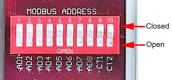
2021-10-04 - 13 -DIP Switch Configuration
Set these switches to the open or closed position for your application.
Modbus Address
Node Address:
DIP1-8: These switches allow you to assign a unique address to each MX4-R2 that
may be in the system using either Modbus or CAN communication. This allows the
client controller to differentiate between the modules. Addressing is done in binary
format, with each switch increasing value by factor of 2. For example, to name the
controller address 5, set switch DIP1 and DIP4 to the CLOSED position. Valid
settings are from 1 to 253.
NOTE: To restore module to factory settings of input type, baud rate
and ethernet IP setup, momentarily set all switches to 0.
Stop Bits: For addresses < 31, the RS485 port will use 1 stop bit. For addresses > 31,
the RS485 port will use 2 stop bits.
CAN Termination
DIP9: This switch provides a 120Ω termination resistor for the CAN communication
chain. CAN must be wired in a daisy chain configuration. Set this switch to CLOSED
only when the module is the end of the network. See control panel drawings for
designation.
RS485 Termination
DIP10: This switch provides a 120Ω termination resistor for the RS485
communication chain. RS485 must be wired in a daisy chain configuration. Set this
switch to CLOSED only when the module is the end of the network. See control panel
drawings for designation.
Section 50 00-02-1024
2021-10-04 - 14 -Ethernet
The MX4-R2 is equipped with two Ethernet communications ports. The ports are marked
ETHERNET 1 and ETHERNET 2. An LED lights when the port is active transmitting or
receiving a message, and an LED lights to indicate Network and Module status
WARNING: Explosion hazard – Do not disconnect the Ethernet port unless the
power has been switched off or the area is known to be non-hazardous.
Below is an 8P8C modular connector (often called RJ45) commonly used on Cat 5 cables in
Ethernet networks.
Section 50 00-02-1024
2021-10-04 - 15 -Twisted-pair Ethernet standards are such that the majority of cables can be wired "straight-
through" (pin 1 to pin 1, pin 2 to pin 2 and so on), but others may need to be wired in the
"crossover" form (receive to transmit and transmit to receive). The MX4-R2 can automatically
detect another computer connected with a straight-through cable and then automatically
introduce the required crossover, if needed with no intervention by the installer. 10BASE-T and
100BASE-TX only require two pairs (pins 1-2, 3-6) to operate. Since Category 5 cable has four
pairs, the spare pairs (pins 4–5, 7–8) in 10- and 100-Mbit/s configurations are not used.
The MX4-R2 uses autonegotiation, an Ethernet procedure by which two connected devices
choose common transmission parameters, such as speed, duplex mode and flow control. In
this process, the connected devices first share their capabilities regarding these parameters
and then choose the highest performance transmission mode they both support. The MX4-R2
supports 10 and 100 Mbit/s over two-pair Cat5 or better cable.
Important: For Entity Parameters or Power Supply and Grounding, refer to Wire Connections.
NOTE: These circuits are not required to be in conduit if the all
requirements for ic protection are met and Authority Having Jurisdiction
(AHJ) allows.
Section 50 00-02-1024
2021-10-04 - 16 -Communications Physical Layer: The MX4-R2 module features two Ethernet ports, one RS485 serial communication port and one CAN bus 2.0B communication port. Ethernet Interconnect: Two RJ45 jacks. This connection may require setting the IP address of the module to the desired network configuration. Ethernet port settings can be changed by modifying Modbus registers. Default setting is 192.168.0.11 IP, 255.255.255.0 network mask, 192.168.0.1 Gateway. Ethernet Protocol: Modbus TCP/IP server. Refer to the Modbus RTU map provided in this manual for a detailed mapping of the available data and data scaling. Serial RS485 Interconnect: Screw terminals. Typically this connection uses twisted shielded pair cable with 120 ohm impedance. RS485 networks are 2-wire, half-duplex and feature an “A” terminal 49 and “B” terminal 50. The A terminal is the + or non-inverting signal, and the B terminal is the – or inverting signal. These signal lines will take turns transmitting and receiving depending on the device using the RS485 network at any given instant. Serial Baud Rate: Default 9600, adjustable up to 115.2k. Serial Stop Bits: The module will respond with 1 stop bit for Modbus RTU addresses 1 through 31 and 2 stop bits for addresses 32 through 253. This maintains flexibility for systems requiring 2 stop bits. Serial Protocol: Modbus RTU server. The module may be polled by the Modbus RTU Client without any additional timing delays and response times will be < 100mS. This may vary depending on the amount of data requested. Modbus RTU timeout settings should be set to >= 400mS. Refer to the Modbus RTU map provided in this manual for a detailed mapping of the available data and data scaling. CAN bus Interconnect: Screw terminals. Typically this connection uses twisted pair cable with 120 ohm impedance to connect to a FW Murphy Controller. CAN bus networks are 2-wire with a “HI” terminal 52 and “LOW” terminal 53. CAN bus Baud Rate: 250k / 1Mb auto sense. CAN bus Protocol: Proprietary for FW Murphy Controllers. PC Connection: Reading data from the module into a PC may be done with an Ethernet connection and Modbus TCP/IP client software or RS485 connection and Modbus RTU Client software. A serial interface converter that can convert USB to RS485 would be needed for a serial connection. (FW Murphy MConfig™ Software and P/N 53702325 may be used for this purpose.) Section 50 00-02-1024 2021-10-04 - 17 -
Modbus Holding Register Description
All data will be contained in 16-bit Modbus Holding Registers. Following the Modbus RTU and
Modbus TCP/IP specification, the Most Significant Byte in a 16-bit word is broadcast first,
followed by the Least Significant Byte. The module responds to Modbus Function Code 03
(Read Holding Registers), Function Code 06 (Preset Single Holding Register) and Function
Code 16 (Preset Multiple Holding Register). Polling invalid/non-existent data will result in
Modbus Exception Code response from the module.

Modbus                                 Read/
                       Description             Data Range       Data Units   Definitions / Sample Data
Register                               Write
  400001    Hardware Type                R          32              ID              Module name
 400002 –
            Factory Use                  R
  400004

  400005    Bootloader Build Version     R       0 – 65535                         Version number

  400006    Not Used                     R

  400007    Firmware Number              R       0 – 65535                         Version number

  400008    Firmware Build Version       R       0 – 65535                         Version number

  400009    Firmware Checksum MSW        R       0 – 65535

  400010    Firmware Checksum LSW        R       0 – 65535

  400011    Firmware Major Version       R       0 – 65535                         Version number

  400012    Firmware Minor Version       R       0 – 65535                         Version number

  400013    Bootloader Major Version     R       0 – 65535                         Version number

  400014    Bootloader Minor Version     R       0 – 65535                         Version number

 400015 –
            Factory Use                  R
  400020

  400021    System Voltage               R        0-65535         Vdc x10    0 = 0.0 VDC, 320 = 32.0 VDC

  400022    Raw Channel 1                R     -32767 – 32768     mV x100    0 = 0.00 mV, 7500 = 75.00 mV

  400023    Raw Channel 2                R     -32767 – 32768     mV x100    0 = 0.00 mV, 7500 = 75.00 mV

  400024    Raw Channel 3                R     -32767 – 32768     mV x100    0 = 0.00 mV, 7500 = 75.00 mV

  400025    Raw Channel 4                R     -32767 – 32768     mV x100    0 = 0.00 mV, 7500 = 75.00 mV

  400026    Raw Channel 5                R     -32767 – 32768     mV x100    0 = 0.00 mV, 7500 = 75.00 mV

  400027    Raw Channel 6                R     -32767 – 32768     mV x100    0 = 0.00 mV, 7500 = 75.00 mV

  400028    Raw Channel 7                R     -32767 – 32768     mV x100    0 = 0.00 mV, 7500 = 75.00 mV

  400029    Raw Channel 8                R     -32767 – 32768     mV x100    0 = 0.00 mV, 7500 = 75.00 mV

  400030    Raw Channel 9                R     -32767 – 32768     mV x100    0 = 0.00 mV, 7500 = 75.00 mV

  400031    Raw Channel 10               R     -32767 – 32768     mV x100    0 = 0.00 mV, 7500 = 75.00 mV

  400032    Raw Channel 11               R     -32767 – 32768     mV x100    0 = 0.00 mV, 7500 = 75.00 mV

  400033    Raw Channel 12               R     -32767 – 32768     mV x100    0 = 0.00 mV, 7500 = 75.00 mV

  400034    Raw Channel 13               R     -32767 – 32768     mV x100    0 = 0.00 mV, 7500 = 75.00 mV

  400035    Raw Channel 14               R     -32767 – 32768     mV x100    0 = 0.00 mV, 7500 = 75.00 mV

  400036    Raw Channel 15               R     -32767 – 32768     mV x100    0 = 0.00 mV, 7500 = 75.00 mV

Section 50                                                                                00-02-1024
2021-10-04                                     - 18 -
Modbus Read/
Description Data Range Data Units Definitions / Sample Data
Register Write
400037 Raw Channel 16 R -32767 – 32768 mV x100 0 = 0.00 mV, 7500 = 75.00 mV
400038 Raw Channel 17 R -32767 – 32768 mV x100 0 = 0.00 mV, 7500 = 75.00 mV
400039 Raw Channel 18 R -32767 – 32768 mV x100 0 = 0.00 mV, 7500 = 75.00 mV
400040 Raw Cold Junction Input R 0 – 65535 A/D count
400041 Not Used R
400042 Frequency input R 0 – 10,000 Hz
400043 Factory Use R
400044 Not Used R
400045 Filtered Temperature Channel 1 R -2000 to +25000 deg F X10
400046 Filtered Temperature Channel 2 R -2000 to +25000 deg F X10
400047 Filtered Temperature Channel 3 R -2000 to +25000 deg F X10
400048 Filtered Temperature Channel 4 R -2000 to +25000 deg F X10
400049 Filtered Temperature Channel 5 R -2000 to +25000 deg F X10
400050 Filtered Temperature Channel 6 R -2000 to +25000 deg F X10
400051 Filtered Temperature Channel 7 R -2000 to +25000 deg F X10
400052 Filtered Temperature Channel 8 R -2000 to +25000 deg F X10
400053 Filtered Temperature Channel 9 R -2000 to +25000 deg F X10
400054 Filtered Temperature Channel 10 R -2000 to +25000 deg F X10
400055 Filtered Temperature Channel 11 R -2000 to +25000 deg F X10
400056 Filtered Temperature Channel 12 R -2000 to +25000 deg F X10
400057 Filtered Temperature Channel 13 R -2000 to +25000 deg F X10
400058 Filtered Temperature Channel 14 R -2000 to +25000 deg F X10
400059 Filtered Temperature Channel 15 R -2000 to +25000 deg F X10
400060 Filtered Temperature Channel 16 R -2000 to +25000 deg F X10
400061 Filtered Temperature Channel 17 R -2000 to +25000 deg F X10
400062 Filtered Temperature Channel 18 R -2000 to +25000 deg F X10
400063 Cold Junction Temperature R -400 to +1850 F deg F X10
400064 Not Used R
400065 Not Used R
400066 Not Used R
400067 Unfiltered Temperature Channel 1 R -2000 to +25000 deg F X10
400068 Unfiltered Temperature Channel 2 R -2000 to +25000 deg F X10
400069 Unfiltered Temperature Channel 3 R -2000 to +25000 deg F X10
400070 Unfiltered Temperature Channel 4 R -2000 to +25000 deg F X10
400071 Unfiltered Temperature Channel 5 R -2000 to +25000 deg F X10
400072 Unfiltered Temperature Channel 6 R -2000 to +25000 deg F X10
400073 Unfiltered Temperature Channel 7 R -2000 to +25000 deg F X10
Section 50 00-02-1024
2021-10-04 - 19 -Modbus Read/
Description Data Range Data Units Definitions / Sample Data
Register Write
400074 Unfiltered Temperature Channel 8 R -2000 to +25000 deg F X10
400075 Unfiltered Temperature Channel 9 R -2000 to +25000 deg F X10
400076 Unfiltered Temperature Channel 10 R -2000 to +25000 deg F X10
400077 Unfiltered Temperature Channel 11 R -2000 to +25000 deg F X10
400078 Unfiltered Temperature Channel 12 R -2000 to +25000 deg F X10
400079 Unfiltered Temperature Channel 13 R -2000 to +25000 deg F X10
400080 Unfiltered Temperature Channel 14 R -2000 to +25000 deg F X10
400081 Unfiltered Temperature Channel 15 R -2000 to +25000 deg F X10
400082 Unfiltered Temperature Channel 16 R -2000 to +25000 deg F X10
400083 Unfiltered Temperature Channel 17 R -2000 to +25000 deg F X10
400084 Unfiltered Temperature Channel 18 R -2000 to +25000 deg F X10
400085 -
Factory Use R
400087
0 = J, 1 = K, 2 =
Strict option enables advanced wire
100Ω Pt RTD,
400088 Channel 1 type R/W 0-5 fault detection for DC-/DC+ mV
4 = J Strict,
leak/temperature shift.
5 = K Strict
0 = J, 1 = K,
400089 Channel 2 type R/W 0–5 4 = J Strict,
5 = K Strict
0 = J, 1 = K, 2 =
100Ω Pt RTD,
400090 Channel 3 type R/W 0-5
4 = J Strict,
5 = K Strict
0 = J, 1 = K,
400091 Channel 4 type R/W 0–5 4 = J Strict,
5 = K Strict
0 = J, 1 = K, 2 =
100Ω Pt RTD,
400092 Channel 5 type R/W 0-5
4 = J Strict,
5 = K Strict
0 = J, 1 = K,
400093 Channel 6 type R/W 0–5 4 = J Strict,
5 = K Strict
0 = J, 1 = K, 2 =
100Ω Pt RTD,
400094 Channel 7 type R/W 0-5
4 = J Strict,
5 = K Strict
0 = J, 1 = K,
400095 Channel 8 type R/W 0–5 4 = J Strict,
5 = K Strict
0 = J, 1 = K, 2 =
100Ω Pt RTD,
400096 Channel 9 type R/W 0-5
4 = J Strict,
5 = K Strict
0 = J, 1 = K,
400097 Channel 10 type R/W 0–5 4 = J Strict,
5 = K Strict
0 = J, 1 = K, 2 =
100Ω Pt RTD,
400098 Channel 11 type R/W 0-5
4 = J Strict,
5 = K Strict
0 = J, 1 = K,
400099 Channel 12 type R/W 0–5 4 = J Strict,
5 = K Strict
Section 50 00-02-1024
2021-10-04 - 20 -Modbus Read/
Description Data Range Data Units Definitions / Sample Data
Register Write
0 = J, 1 = K, 2 =
100Ω Pt RTD,
400100 Channel 13 type R/W 0-5
4 = J Strict,
5 = K Strict
0 = J, 1 = K,
400101 Channel 14 type R/W 0–5 4 = J Strict,
5 = K Strict
0 = J, 1 = K, 2 =
100Ω Pt RTD,
400102 Channel 15 type R/W 0-5
4 = J Strict,
5 = K Strict
0 = J, 1 = K,
400103 Channel 16 type R/W 0–5 4 = J Strict,
5 = K Strict
0 = J, 1 = K, 2 =
100Ω Pt RTD,
400104 Channel 17 type R/W 0-5
4 = J Strict,
5 = K Strict
0 = J, 1 = K,
400105 Channel 18 type R/W 0–5 4 = J Strict,
5 = K Strict
Modify this value to offset the cold
400106 Cold junction offset R/W -32768 to +32767 deg F
junction reading
400107 Not Used R
400108 Not Used R
400109 Communication Timeout R/W 0 – 65535 time in seconds
1=9600, 2=19.2k, 3=38.4k,
400110 Serial Port Baud Rate R/W 1-5 Enumeration
4=57.6k, 5=115.2k
400111-
Factory Use R
400140
1 = TC OK, 2 = RTD OK, 3 = OPEN,
4 = MINOR SHORT DC-, 5=
400141 Channel 1 Status R 1 –7 enumeration MAJOR SHORT DC-, 6 = MINOR
SHORT DC+, 7 = MAJOR SHORT
DC+
1 = TC OK, 2 = RTD OK, 3 = OPEN,
4 = MINOR SHORT DC-, 5=
400142 Channel 2 Status R 1 –7 enumeration MAJOR SHORT DC-, 6 = MINOR
SHORT DC+, 7 = MAJOR SHORT
DC+
1 = TC OK, 2 = RTD OK, 3 = OPEN,
4 = MINOR SHORT DC-, 5=
400143 Channel 3 Status R 1 –7 enumeration MAJOR SHORT DC-, 6 = MINOR
SHORT DC+, 7 = MAJOR SHORT
DC+
1 = TC OK, 2 = RTD OK, 3 = OPEN,
4 = MINOR SHORT DC-, 5=
400144 Channel 4 Status R 1 –7 enumeration MAJOR SHORT DC-, 6 = MINOR
SHORT DC+, 7 = MAJOR SHORT
DC+
1 = TC OK, 2 = RTD OK, 3 = OPEN,
4 = MINOR SHORT DC-, 5=
400145 Channel 5 Status R 1 –7 enumeration MAJOR SHORT DC-, 6 = MINOR
SHORT DC+, 7 = MAJOR SHORT
DC+
1 = TC OK, 2 = RTD OK, 3 = OPEN,
4 = MINOR SHORT DC-, 5=
400146 Channel 6 Status R 1 –7 enumeration MAJOR SHORT DC-, 6 = MINOR
SHORT DC+, 7 = MAJOR SHORT
DC+
Section 50 00-02-1024
2021-10-04 - 21 -Modbus Read/
Description Data Range Data Units Definitions / Sample Data
Register Write
1 = TC OK, 2 = RTD OK, 3 = OPEN,
4 = MINOR SHORT DC-, 5=
400147 Channel 7 Status R 1 –7 enumeration MAJOR SHORT DC-, 6 = MINOR
SHORT DC+, 7 = MAJOR SHORT
DC+
1 = TC OK, 2 = RTD OK, 3 = OPEN,
4 = MINOR SHORT DC-, 5=
400148 Channel 8 Status R 1 –7 enumeration MAJOR SHORT DC-, 6 = MINOR
SHORT DC+, 7 = MAJOR SHORT
DC+
1 = TC OK, 2 = RTD OK, 3 = OPEN,
4 = MINOR SHORT DC-, 5=
400149 Channel 9 Status R 1 –7 enumeration MAJOR SHORT DC-, 6 = MINOR
SHORT DC+, 7 = MAJOR SHORT
DC+
1 = TC OK, 2 = RTD OK, 3 = OPEN,
4 = MINOR SHORT DC-, 5=
400150 Channel 10 Status R 1 –7 enumeration MAJOR SHORT DC-, 6 = MINOR
SHORT DC+, 7 = MAJOR SHORT
DC+
1 = TC OK, 2 = RTD OK, 3 = OPEN,
4 = MINOR SHORT DC-, 5=
400151 Channel 11 Status R 1 –7 enumeration MAJOR SHORT DC-, 6 = MINOR
SHORT DC+, 7 = MAJOR SHORT
DC+
1 = TC OK, 2 = RTD OK, 3 = OPEN,
4 = MINOR SHORT DC-, 5=
400152 Channel 12 Status R 1 –7 enumeration MAJOR SHORT DC-, 6 = MINOR
SHORT DC+, 7 = MAJOR SHORT
DC+
1 = TC OK, 2 = RTD OK, 3 = OPEN,
4 = MINOR SHORT DC-, 5=
400153 Channel 13 Status R 1 –7 enumeration MAJOR SHORT DC-, 6 = MINOR
SHORT DC+, 7 = MAJOR SHORT
DC+
1 = TC OK, 2 = RTD OK, 3 = OPEN,
4 = MINOR SHORT DC-, 5=
400154 Channel 14 Status R 1 –7 enumeration MAJOR SHORT DC-, 6 = MINOR
SHORT DC+, 7 = MAJOR SHORT
DC+
1 = TC OK, 2 = RTD OK, 3 = OPEN,
4 = MINOR SHORT DC-, 5=
400155 Channel 15 Status R 1 –7 enumeration MAJOR SHORT DC-, 6 = MINOR
SHORT DC+, 7 = MAJOR SHORT
DC+
1 = TC OK, 2 = RTD OK, 3 = OPEN,
4 = MINOR SHORT DC-, 5=
400156 Channel 16 Status R 1 –7 enumeration MAJOR SHORT DC-, 6 = MINOR
SHORT DC+, 7 = MAJOR SHORT
DC+
1 = TC OK, 2 = RTD OK, 3 = OPEN,
4 = MINOR SHORT DC-, 5=
400157 Channel 17 Status R 1 –7 enumeration MAJOR SHORT DC-, 6 = MINOR
SHORT DC+, 7 = MAJOR SHORT
DC+
1 = TC OK, 2 = RTD OK, 3 = OPEN,
4 = MINOR SHORT DC-, 5=
400158 Channel 18 Status R 1 –7 enumeration MAJOR SHORT DC-, 6 = MINOR
SHORT DC+, 7 = MAJOR SHORT
DC+
465197 IP Address Part 1 R/W 0-255 octet Ethernet setting
465198 IP Address Part 2 R/W 0-255 octet Ethernet setting
465199 IP Address Part 3 R/W 0-255 octet Ethernet setting
Section 50 00-02-1024
2021-10-04 - 22 -Modbus Read/
Description Data Range Data Units Definitions / Sample Data
Register Write
465200 IP Address Part 4 R/W 0-255 octet Ethernet setting
465201 Network Mask Part 1 R/W 0-255 octet Ethernet setting
465202 Network Mask Part 2 R/W 0-255 octet Ethernet setting
465203 Network Mask Part 3 R/W 0-255 octet Ethernet setting
465204 Network Mask Part 4 R/W 0-255 octet Ethernet setting
465205 Gateway Address Part 1 R/W 0-255 octet Ethernet setting
465206 Gateway Address Part 2 R/W 0-255 octet Ethernet setting
465207 Gateway Address Part 3 R/W 0-255 octet Ethernet setting
465208 Gateway Address Part 4 R/W 0-255 octet Ethernet setting
465209 DNS1 Address Part 1 R/W 0-255 octet Ethernet setting
465210 DNS1 Address Part 2 R/W 0-255 octet Ethernet setting
465211 DNS1 Address Part 3 R/W 0-255 octet Ethernet setting
465212 DNS1 Address Part 4 R/W 0-255 octet Ethernet setting
465213 DNS2 Address Part 1 R/W 0-255 octet Ethernet setting
465214 DNS2 Address Part 2 R/W 0-255 octet Ethernet setting
465215 DNS2 Address Part 3 R/W 0-255 octet Ethernet setting
465216 DNS2 Address Part 4 R/W 0-255 octet Ethernet setting
0=static ip / no auto IP
1= DHCP enabled / no auto IP
2 = static ip / use Auto IP if no
465217 Ethernet IP Options R/W 0-4 Bitmap
DHCP or IP
3 = DHCP enabled / use Auto IP if
no DCHP or IP
465218 MAC Address word 1 R 0 – 65535
465219 MAC Address word 2 R 0 – 65535
465220 MAC Address word 3 R 0 – 65535
Register 400001 Value Description
Register 400001 is a read-only register. This register holds the model number of the hardware.
If you are using multiple Comm modules, it is sometimes helpful to confirm that you are
communicating with the expected module type. In this case, it will return 32.
Unfiltered Temperature Readings (400045 – 400064)
Registers 400045 – 400064 are read-only registers. The values returned in these registers are
signed 16-bit data. These channels are the actual readings from the connected sensor.
Channels are shown in degrees F x 10. For example, a read value of 1200 means 120°F is
being read.
NOTE: These values are not averaged. The device reading these values
may need additional software filtering to remove noise in the readings.
Section 50 00-02-1024
2021-10-04 - 23 -Filtered Temperature Readings (400067 – 400084)
Registers 400067 – 400084 are read-only registers. The values returned in these registers are
signed 16-bit data. These channels are filtered internally with a median value of 3 samples and
then running average of last 4 readings. This will require approximately 400ms for an accurate
reading on initial powerup. Thermocouple channels are shown in deg F x 10. For example, a
read value of 1200 means 120°F is being read.
NOTE: These values are generally more desirable to use by a controller.
Software filtering has been internally applied by the module and no
additional filtering is necessary by the controller.
Channel Type (400088 – 400105)
Registers 400088 – 400105 are read/write registers. This will allow you to configure what type
of sensor is attached to each channel. *Only odd-numbered channels may be configured as
RTD type. When configured as RTD, the adjacent even-numbered channel is not available for
use, and the type data will be ignored. Use the list below to determine what value you should
write based on the sensor installed.
0 – Type J thermocouple
1 – Type K thermocouple
2 – 100Ω Pt 3-wire RTD
3 – *Type J thermocouple with advanced (strict) wire fault detection enabled.
4 – *Type K thermocouple with advanced (strict) wire fault detection enabled
*Applies to firmware version 3.1.10113 or higher.
Channel Status (400141 – 400158)
Registers 400141 – 400158 are read-only registers. The values between 1-7 show channel
status. The MX4-R2 can detect shorts to DC-, shorts to DC+ and open circuit for the
thermocouple and RTD wiring.
It also detects leaking current to DC- or DC+ which will start causing errors in readings. This is
generally due to breakdown of insulation. As this condition worsens, the status may change to
indicate a short.
Section 50 00-02-1024
2021-10-04 - 24 -Notes Section 50 00-02-1024 2021-10-04 - 25 -
You can also read