Invitation for Bid Equipment and Supplies - 2021 Aquapark Pool Heater
←
→
Page content transcription
If your browser does not render page correctly, please read the page content below

Invitation for Bid
      Equipment and Supplies
            3/23/2021

2021 Aquapark Pool Heater

           Bid Opening:
   Friday, April 2nd, 1:00pm
         636 Ridge Road
     Highland Park, IL 60035

            Tony Matzke
   Park District of Highland Park
          636 Ridge Road
     Highland Park, IL 60035
Park District of Highland Park
                                                        2021 Aquapark Pool Heater

                                                          TABLE OF CONTENTS

ADVERTISEMENT FOR BID .................................................................................................................... 4
INVITATION FOR BID ............................................................................................................................... 4
INSTRUCTIONS TO BIDDERS ................................................................................................................. 5
GENERAL TERMS...................................................................................................................................... 7
ACKNOWLEDGEMENT OF DOCUMENTS ............................................................................................ 9
BID FORM ................................................................................................................................................. 10
CONTRACTOR’S CERTIFICATION OF ELIGIBILITY ........................................................................ 12
SPECIFICATIONS ..................................................................................................................................... 13

                                                                             2
Park District of Highland Park
                                    2021 Aquapark Pool Heater

                                 ADVERTISEMENT FOR BID

The Park District of Highland Park is accepting sealed bids for the following 2021 Aquapark
Pool Heater. Questions regarding this bid should be directed to Tony Matzke at 847.579.4063 or
tmatzke@pdhp.org.

The bid packet, specifications and plans are available on our website at
http://www.pdhp.org/bids-rfps/. Please note that if you intend to submit a bid for this project,
then it is your responsibility to register with Tony Matzke via tmatzke@pdhp.org or (847) 579-
4063. This will identify that you have downloaded the bid documents, and you will then be
considered a registered plan holder. Sealed bids for these items will be received no later than
1:00pm on Friday, April 2nd, at which time they will be publicly opened and read aloud.

Completed bids must be submitted in sealed opaque envelopes marked 2021 Aquapark Pool
Heater and mailed or brought into the Park District of Highland Park, 636 Ridge Road, Highland
Park, IL 60035; Attn: Brian Romes, Secretary.

The Park Board of the Park District of Highland Park reserves the right to reject any or all bids in
full or in part, if it shall deem it in the public interest to do so. In submitting a bid, Contractor
acknowledges that Contractor must, to the extent that it applies, comply with all requirements of
the Illinois Prevailing Wage Act and all other applicable Illinois laws.

                           PARK DISTRICT OF HIGHLAND PARK
                                     /s/ Brian Romes
                                 Secretary of the Board of
                                   Park Commissioners

Published: Lake County News Sun

                                                  3
Park District of Highland Park
                                     2021 Aquapark Pool Heater

                                      INVITATION FOR BID

The Park District of Highland Park is seeking sealed bids for the following equipment or supplies:
One (1) Raypak XTherm, P-2005A, Heater W/PVC Vent option. The bid is to include all costs
F.O.B. Park District of Highland Park, Highland Park, Illinois. “F.O.B. Park District of Highland
Park, Highland Park, Illinois”, is defined as the total price to the Park District, including all freight
and delivery charges to its facility. The bid is to include any training and warranties specified
below. Under no circumstances may prepaid charges be added to the invoice.

Refer to the following specifications:

    1. Anticipated Award Date                     4/28/2021
    2. Equipment Delivery No Later Than           5/21/2021

The bid packet, specifications and plans are available on our website at
http://www.pdhp.org/bids-rfps/. Please note that if you intend to submit a bid for this project,
then it is your responsibility as a potential contractor to register with Tony Matzke via
tmatzke@pdhp.org or (847) 579-4063. This will identify that you have downloaded the bid
documents, and you will then be considered a registered plan holder. Sealed bids for these items
will be received no later than 1:00pm on Friday, April 2nd, at which time they will be publicly
opened and read aloud.

Completed bids must be submitted in sealed opaque envelopes marked “2021 Aquapark
Pool Heater” and mailed or brought into the Park District of Highland Park, 636 Ridge
Road, Highland Park, Illinois; Attn: Brian Romes, Secretary.

All bids must be submitted on the forms included in the bid documents.

All bids will remain firm for 90 calendar days after the bid opening. The Park District of Highland
Park reserves the right to reject any or all bids or to accept any bids, which in its judgment, will be
in the best interest of the public or to waive any informalities in bidding. Only bids in compliance
with the provisions of the Contract Documents will be considered. No bids shall be withdrawn
after the opening of the bids for a period of ninety (90) calendar days after the bid date opening.

The Park District of Highland Park encourages small and minority businesses and women’s
business firms to submit bids on the approved project and successful contract bidders to utilize
small and minority businesses and women’s businesses as sub-contractors for supplies, equipment,
services, and construction.

                                                   4
Park District of Highland Park
                                     2021 Aquapark Pool Heater

                                 INSTRUCTIONS TO BIDDERS

For the purpose of these specifications, "Owner" shall refer to the Park District of Highland Park,
and "Vendor" shall refer to the party entering into the contract for the performance of the specified
work, and his or her legal representatives or agents. Upon award of the Contract, these instructions
shall become a part of the Contract Documents.

PLANS AND SPECIFICATIONS
The bid packet, specifications and plans are available on our website at http://www.pdhp.org/bids-
rfps. Please note that if you intend to submit a bid for this project, then it is your responsibility as
a potential contractor to register with Tony Matzke via tmatzke@pdhp.org or (847) 579-4063. This
will identify that you have downloaded the bid documents, and you will then be considered a
registered plan holder.

TOTAL PRICING
Quote all prices F.O.B. Highland Park, Illinois. F.O.B. Highland Park, Illinois, is defined as the
total price to the Park District, including all freight and delivery charges to its facility. Under no
circumstances may prepaid charges be added to the invoice. Vendor is advised that the Park
District may choose to pay by credit card.

BID FORM
Vendor shall submit the bid form provided which shall be filled out completely and addressed as
follows: Park District of Highland Park, 636 Ridge Rd., Highland Park, IL 60035.

On the outside of the bid envelope, each sealed bid shall also contain the notation “SEALED
BID” along with

       A) 2021 Aquapark Pool Heater
       B) Bidder’s Company Name
       C) Date and Time of Bid Opening

Bids for One (1) Raypak XTherm, P-2005A, Heater W/PVC Vent option shall be received at or
before 1:00pm on Friday, April 2nd, at which time they will be opened and read publicly.

ACCEPTANCE OR REJECTION OF BID
Owner reserves the right to accept or reject any or all bids. In determining the lowest responsive
and responsible bidder, Owner further reserves the right to combine or separate or delete any
section of work or alternates or items in the bid if it is in the best interest of Owner.

NON-BARRED BIDDING
Vendor must certify that it is not barred from bidding on this contract as a result of a conviction
for the violation of state laws prohibiting bid-rigging or bid-rotating by executing the included
certification.

ASSIGNMENT
Vendor shall not assign any part of this contract or award any work under this contract without
prior written approval from the Owner.

                                                   5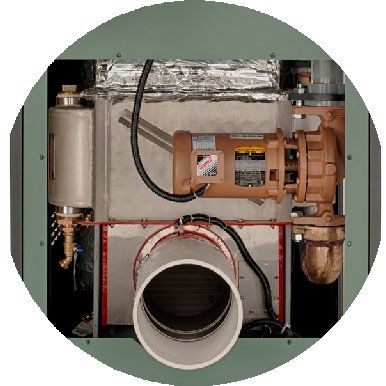
Park District of Highland Park
                                   2021 Aquapark Pool Heater

INSURANCE
Vendor warrants that the manufacturer of the goods has completed products operations insurance
to cover any defects in the product.

DELIVERY
Vendor warrants that it can meet the delivery date requirements set forth herein.

                                                 6
Park District of Highland Park
                                    2021 Aquapark Pool Heater

                                       GENERAL TERMS

ERRORS AND OMISSIONS
All Vendors are requested to notify Owner immediately of any errors or omissions that are
encountered in the specifications

INVESTIGATION
Owner reserves the right to investigate the quality and fitness of the equipment or supplies offered
or the reliability of the Vendor. Each vendor shall supply the information requested herein in order
to be considered.

TAX EXEMPTION
Owner is not subject to federal excise tax or Illinois Retailer’s Occupation Tax. Owner’s Tax
Exempt ID # is available by request.

COMPLETION OF CONTRACT
Failure of the Vendor to complete the work or furnish the equipment or supplies in accordance
with the Specifications shall constitute a breach of the Contract.

SUBSTITUTIONS
The equipment and supplies stated in the Specifications are for the purpose of establishing a quality
required or performance goal to be achieved as a minimum requirement. Because Owner does not
wish to rule out other competition, whenever a specific item and description is stated, Owner has
added the phrase "or approved equal.” Vendors proposing to use an alternate must request
approval in writing from Owner no later than five (5) business days prior to the bid opening. Bids
which propose to use a non-approved alternate will be rejected. Owner shall be the sole judge as
to whether any substitute is of equivalent or better quality and the Vendors waive any right to
challenge such decision.

ADDENDA AND INTERPRETATION
All interpretations and requests for interpretations of the Bid Documents must be made in writing.
Any addenda shall become part of the Contract Documents.

AWARD SELECTION
Owner will make an award, if any, based upon the basis of the best interests of Owner as
determined by Owner in the exercise of its sole discretion.

CONTRACT
The Vendor to whom the project is awarded will enter into a contract with Owner in the form of
this purchase order or other purchase authorization document.

DELIVERY DATE
Prices quoted must include delivery and delivery arrangements will be made with the successful
Vendor(s) immediately after board approval. Delivery dates are listed on the Bid Form.

COMPLIANCE WITH LAWS
The provision of any goods, and the goods themselves, must comply with all applicable federal,
state, county and local laws, ordinances, rules and regulations and orders.

                                                  7
Park District of Highland Park
2021 Aquapark Pool Heater
PARKING AND TRAFFIC
Parking of construction or delivery vehicles on the site by the Vendor shall not inhibit public access
nor prevent access for emergency or other official vehicles. Parking of private vehicles on the site
by the Vendor is prohibited unless said vehicle is necessary in the execution of the Contract. No
construction or delivery vehicles shall be parked near or under any existing vegetation on the site.
WARRANTY/GUARANTEE
Vendor warrants to Owner that the equipment and supplies furnished under the Contract
Documents will be of good quality, unless otherwise required or permitted under the
Specifications, that the work and materials will be free from defects not inherent in the quality
required or permitted, and that the goods will conform to the requirements of the Specifications,
and that Vendor has completed products insurance coverage for all products supplied for this Bid.
Defective materials, equipment or workmanship occurring within the Warranty period may be
repaired where such produces results conforming to the Contract Documents relating to
appearance, performance and reliability. Where the nature of the defective materials, equipment
or workmanship is such that acceptable results cannot be obtained by repair, such defective items
shall be removed and replaced with new materials, equipment or workmanship complying with
the Contract Documents.
SCOPE
The Bid shall provide all requested quantities and shall furnish all equipment to complete the
delivery as indicated in these Contract Documents and Specifications. The total quantities in the
following Bid Form are approximate only. Payment shall be based upon the unit prices listed and
the actual amount of product delivered.
FOIA RESPONSIBILITIES
The winning Vendor agrees to maintain, without charge to Owner, all records and documents for
projects of Owner in compliance with the Freedom of Information Act, 5 ILCS 140/1 et seq. In
addition, Vendor shall produce records which are responsive to a request received by Owner under
the Freedom of Information Act so that the Owner may provide records to those requesting them
within the time frames required. If additional time is necessary to compile records in response to
a request, then Vendor shall so notify Owner and if possible, Owner shall request an extension so
as to comply with the Act. In the event that Owner is found to have not complied with the Freedom
of Information Act due to Vendor’s failure to produce documents or otherwise appropriately
respond to a request under the Act, then Vendor shall indemnify and hold Owner harmless, and
pay all amounts determined to be due including but not limited to fines, costs, attorneys’ fees and
penalties.
INDEMNIFICATION
To the fullest extent permitted by law, Vendor shall indemnify and hold harmless Owner and its
officers, officials, employees, volunteers and agents from and against all claims, damages, losses
and expenses, including but not limited to legal fees (attorney’s and paralegals’ fees and court
costs), arising out of or resulting from the equipment and supplies purchased herein.
8Park District of Highland Park
2021 Aquapark Pool Heater
ACKNOWLEDGEMENT OF DOCUMENTS
1. Receipt of Documents: Bidder has received a complete set of specifications and
understands the meaning of their content and shall willingly comply with the guidelines
set forth in these documents.
Yes No
2. Identification of Documents Received: The following is a checklist of documents that
should appear in the Bid Documents. Please complete the checklist and contact the Park
District if any of the documents have been omitted.
Yes No
ADVERTISMENT FOR BID
INVITATION TO BID
INSTRUCTIONS TO BIDDERS
GENERAL TERMS
ACKNOWLEDGEMENT OF DOCUMENTS
BID FORM
CERTIFICATION OF ELIGIBILITY
SPECIFICATIONS
9Park District of Highland Park
2021 Aquapark Pool Heater
BID FORM
(Page 1 of 2)
TO: Park District of Highland Park
636 Ridge Road
Highland Park, IL 60035
FROM:
Company
Street Address
City, State, Zip
Phone
FOR: 2021 Hidden Creek Aquapark Pool Heaters
BASE PROPOSAL:
One (1) Raypak XTherm, P-2005A, Heater W/PVC Vent option. $
Alternative equipment will not be considered.
Net Delivered Price
(Less federal and state tax) $
If awarded the contract based on the above, we agree to deliver One (1) Raypak XTherm,
P-2005A, Heater W/PVC Vent option to the Park District by 5/21/2021.
10Park District of Highland Park
2021 Aquapark Pool Heater
BID FORM
(Page 2 of 2)
Receipt of Addenda: The receipt of the following addenda is hereby acknowledged:
Addendum No. , Dated
Addendum No. , Dated
The undersigned bidder has carefully examined the specifications for the 2021 Aquapark Pool
Heater as prepared by the Owner and having completely familiarized him/herself with local
conditions affecting the cost: hereby states that he/she will provide the above equipment at the
above prices and will accept as full and complete payment therefore the bid amount set forth.
BY:
Name and Title of Authorized Agent
Authorized Signature
Date
11Park District of Highland Park
2021 Aquapark Pool Heater
CONTRACTOR’S CERTIFICATION OF ELIGIBILITY
In Compliance 720 ILCS 5/33E-11:
,a(n)
Print name of Contractor Individual, Partnership, Corporation
as part of his bid or proposal on the above referenced Contract, hereby certifies that the Contractor
is not barred from bidding on the above referenced contract or entering into a contract with the
Park District of Highland Park as a result of a violation of either Section 33E-3 Bid-rigging or
33E-4 Bid-stating of Article 33E of the Illinois Criminal Code, 720 ILCS 5/33E-1, et. seq., as
amended.
Date
Contractor
By:
Its:
Title
STATE OF ILLINOIS )
) SS
COUNTY OF )
I, the undersigned, a notary public in and for the State and County aforesaid, hereby certify that
appeared before me this day in person and, being first duly sworn on oath, acknowledged that
he/she is authorized to act on behalf of Contractor, and that he/she executed the foregoing
certificate as his/her free act and deed and as the act and deed of Contractor.
DATED: , 2021
Notary Public
[Notary Seal]
12Park District of Highland Park
2021 Aquapark Pool Heater
SPECIFICATIONS
• Provide One (1) new Raypak Xtherm Model P-2005A Heater. Alternative equipment
will not be considered.
• Heater must be fitted with PVC Vent Option (Factory Installed Only)
• Product Brochure and I&O Manual are included for reference.
13XTHERM
®
POOL HEATER
VERSA IC® WITH
RAYMOTE™
HYBRID
DESIGN
MAXIMUM
EFFICIENCYENGINEERED TO PERF
Time honored technology unites with cutting edge
advancement.
The XTherm combines the proven capability of a finned cupronickel tube heat exchanger with a stainless steel
condensing heat exchanger to maximize thermal efficiency (97%) and provide long-term reliability. Raypak’s
XTherm is built with commercial-grade components and materials. From our steel channel base to our stainless
steel flue wrapper, and condensing heat exchanger, you can tell the XTherm is built to last. It’s easy to handle
and install, but still user friendly to service.
Vertical non-condensing
7 “ touchscreen
heat exchanger
display
CPVC water
Low voltage
manifolds
wiring terminal
Cold Water Run
System
316L stainless steel
condensing heat
exchangerORM. BUILT TO LAST.
VERSA IC intelligence with
Raymote connectivity.
Raypak’s VERSA IC combines modulating temperature
control, safety limits, and ignition programming into one
user-friendly integrated control platform. With self-learning
features that prevent equipment damage, this automated
controller is easy to set-up, understand, and use, making it
as close to plug and play as possible.
The VERSA IC system can be remotely monitored through
the Raymote mobile app or web dashboard. With touch-of-
a-button access to vital information, Raymote gives you:
• Real time service notifications to keep you informed.
• View and manage your Raypak systems at multiple sites.
• Instant visibility to historical data and performance
reports.
1 year of Raymote service included.
Raymote retrofit kits available for installed products with the VERSA IC touchscreen.
Indoor or Outdoor Weatherproof Jacket
Safety certified for indoor/outdoor installation. Heavy gauge galvanized steel with a UV-resistant
Every XTherm is direct vent capable and comes powder coat finish is impervious to weather and
standard with an outdoor intake air cover. corrosion.
Small Footprint Easy To Connect
Compact design makes the XTherm the perfect The XTherm high voltage wiring center is located
choice for small spaces and an ideal option for hard on the rear of the boiler. All incoming line voltage
to reach retrofit projects. Footprint is less than 11 ft2 and pump wiring are contained away from the 24V
for 1-2 MM BTUH. control wiring. Wiring the boiler is simple and straight
forward.
Cold Water Run System
The XTherm comes with a factory mounted and plumbed Cold Water Run system, which provides constant
protection against condensation in the non-condensing heat exchanger and maintains optimum inlet
temperatures.
Learn more at raypak.comXTherm - Type P
Models 1005A - 4005
MBTUH (kw/h) Dimensions In. (mm) Lbs. (kg) Clearances in. (mm)
C D N Combustible Service
Model Thermal A B K Ship Minimum Minimum
Input Output Base Overall G Comb.
Efficiency Height Width Flue ø Weight
Depth Depth* Air ø Front
24 30
(610) (762)
999 969 55.25 31 50 57.3 1065
1005A 97% 1-1/4 6 6 12 36
(292.8) (284) (1403) (787) (1270) (1455) (483) Rear
(305) (915)
1500 1455 67.125 31 50 57.5 1234
1505A 97% 1-1/4 8 8 1 24
(439.6) (426.4) (1705) (787) (1270) (1461) (560) Right
(25) (610)
1999 1939 81.125 31 50 57.5 1461
2005A 97% 2** 8 8 Left
1 1
(585.8) (568.3) (2061) (787) (1270) (1461) (663) (25) (25)
2501 2426 68.25 31 97.5 107.5 2656 Top 12
2505 97% 2-1/2 10 10 0
(733) (711) (1734) (787) (2477) (2731) (1205) (indoor) (305)
3000 2910 73.25 31 97.5 107.5 2775
3005 97% 2-1/2 10 10 Floor 0 N/A
(879.2) (852.8) (1861) (787) (2477) (2731) (1259)
3500 3395 78.25 31 97.5 107.5 2925 Vent Stack 1
3505 97% 2-1/2 10 12 N/A
(1025.7) (995) (1988) (787) (2477) (2731) (1327) (indoor) (25)
4000 3880 83.25 31 97.5 109 3058 Vent Cap 12 12
4005 97% 2-1/2 12 12
(1172.3) (1137.1) (2115) (787) (2477) (2769) (1387) (outdoor) (305) (305)
**For natural gas. 1 1/4” NPT for propane.
www.raypak.com
2151 Eastman Avenue Oxnard, CA 93030 805-278-5300
Litho in U.S.A. ©2018 Raypak, Inc. 6200.12L Effective 05-01-19 Replaces 07-15-17INSTALLATION AND
OPERATION MANUAL
ULTRA HIGH EFFICIENCY
Models 1005A - 2005A
Type H, WH, and P
A WARNING: Improper installation, adjustment, alteration, service or maintenance can cause property
damage, personal injury, exposure to hazardous materials* or loss of life. Review the information in this manual
carefully. *This unit contains materials that have been identified as carcinogenic, or possibly carcinogenic,
to humans.
FOR YOUR SAFETY: Do not store or use gasoline or other flammable vapors and liquids or other com-
bustible materials in the vicinity of this or any other appliance. To do so may result in an explosion or
fire.
WHAT TO DO IF YOU SMELL GAS:
• Do not try to light any appliance.
• Do not touch any electrical switch; do not use any phone in your building.
• Immediately call your gas supplier from a neighbor’s phone. Follow the gas supplier’s instructions.
• If you cannot reach your gas supplier, call the fire department.
Installation and service must be performed by a qualified installer, service agency or the gas supplier.
This manual should be maintained in legible condition and kept adjacent to the heater or in a safe place for future
reference.
CATALOG NO. 3400.552E
Effective: 06-10-19
Replaces: 09-20-18
P/N 241513 Rev. 6CONTENTS
1. WARNINGS............................................................ 3 4. CONTROLS ............................................................ 39
1.1. Pay Attention to These Terms ....................... 3 4.1. Ignition Control Functions .......................... 39
2. BEFORE INSTALLATION .............................................4 4.2. High Limit - Manual Reset............................ 39
2.1. Product Receipt .............................................. 4 4.3. High Limit - Auto Reset (Optional) ............... 39
2.2. Model Identification ..................................... 4 4.4. Variable-Speed Injector Pump ..................... 39
2.3. Ratings and Certifications .............................. 4 4.5. Condensate Float Switch ............................. 40
2.4. Installations at Elevation................................. 4 4.6. Flow Switch .................................................. 40
2.5. Component Locations .................................... 5 4.7. Low Water Cut-Off (Optional) ....................... 40
2.6. General Safety ............................................... 6 4.8. High and Low Gas Pressure Switches
(Optional) ..................................................... 40
3. INSTALLATION........................................................... 7 4.9. Blocked Vent Switch .................................... 41
3.1. Installation Codes ........................................... 7 4.10. User Interface .............................................. 41
3.2. Equipment Base ............................................. 7
5. WIRING DIAGRAM FOR MODELS
3.3. Clearances ..................................................... 7
1005A - 2005A ................................................... 47
3.4. Outdoor Installation ........................................ 8
3.5. Combustion and Ventilation Air ................... 8 6. START-UP...................................................................... 48
3.6. Air Supply ..................................................... 11 6.1. Pre Start-up .................................................. 48
3.7. Water Piping ................................................. 12 6.2. Pre Start-up Check ....................................... 48
3.8. Raypak Integral Cold Water Protection ........ 13 6.3. Initial Start-up .............................................. 48
3.9. Hydronic Heating ....................................... 14 6.4. Preparation .................................................. 48
3.10. Pool/Spa Water Chemistry ........................... 21 6.5. Start-Up ........................................................ 49
3.11. Gas Supply ................................................... 21 7. OPERATION ............................................................... 52
3.12. Electrical Power Connections ...................... 23 7.1. Lighting Instructions .................................. 52
3.13. Field Wiring Connections ............................. 24 7.2. To Turn Off Gas To Appliance....................... 52
3.14. Venting - General ......................................... 28 8. TROUBLESHOOTING ........................................... 52
3.15. Vent Terminal Location ................................. 30 8.1. XTherm Error Codes .................................... 52
3.16. Venting Installation Tips ............................... 31 8.2. Heater Errors ............................................... 52
3.17. Vertical Venting Configurations ................. 31 8.3. Heater Faults ............................................... 52
3.18. Horizontal Through-the-Wall and Direct 8.4. XTherm Fault Text ..............................................53
Vent (Category IV) ........................................ 32
3.19. Direct Vent - Vertical ..................................... 34 9. MAINTENANCE..................................................... 55
3.20. Common Venting ........................................... 35 9.1. Suggested Minimum
3.21. Outdoor Installation ...................................... 35 Maintenance Schedule ................................ 55
3.22. Condensate Treatment .................................. 36 9.2. Preventive Maintenance Schedule .............. 56
3.23. PVC Venting Option (D-32) .......................... 37 9.3. Filter Maintenance ..................................... 57
3.24. Centrotherm™ Polypropylene Venting 10. APPENDIX .............................................................. 57
Option (D-33)................................................ 38 10.1. Inside Air Contamination ........................... 57
11. IMPORTANT INSTRUCTIONS FOR THE
COMMONWEALTH OF MASSACHUSETTS ......... 58
Rev 6 reflects the following changes:
Replaced Raypak logo on the front cover page. Updated the elevation rating on page 4. Removed Table N from page 22. Updated
“Wiring Diagram” on page 47. Added a note and a warning to the “Blower Check” on page 49. Updated Figure 55 on page 49.
Removed “Manifold Check” section on page 49. Added the “Touchscreen Toolbox Menu” figure on page 50. Removed Table
Y from page 50. Added the Raymote Troubleshooting sub-section on page 53. Updated “Semi-Annually” section on page 56.
Added a note and updated “As Required” section on page 56. Replaced the “Start-Up Checklist” on page 59. Replaced ISO logo
on the back cover page.
21. WARNINGS
1.1. Pay Attention to These Terms
Indicates the presence of immediate hazards which will cause severe personal injury, death or
A DANGER substantial property damage if ignored.
Indicates the presence of hazards or unsafe practices which could cause severe personal injury,
A WARNING death or substantial property damage if ignored.
Indicates the presence of hazards or unsafe practices which could cause minor personal injury
A CAUTION or product or property damage if ignored.
CAUTION used without the warning alert symbol indicates a potentially hazardous condition
CAUTION
which could cause minor personal injury or product or property damage if ignored.
Indicates special instructions on installation, operation, or maintenance which are important but
NOTE
not related to personal injury hazards.
A DANGER: Make sure the gas on which the heater will A WARNING: Both natural gas and propane have an
operate is the same type as that specified on the heater odorant added to aid in detecting a gas leak. Some people
rating plate. may not physically be able to smell or recognize this
odorant. If you are unsure or unfamiliar with the smell
A WARNING: Should overheating occur or the gas of natural gas or propane, ask your local gas supplier.
supply valve fail to shut, do not turn off or disconnect the Other conditions, such as “odorant fade,” which causes
electrical supply to the heater. Instead, shut off the gas the odorant to diminish in intensity, can also hide,
supply at a location external to the heater. camouflage, or otherwise make detecting a gas leak by
smell more difficult.
A WARNING: Do not use this heater if any part has
been under water. Immediately call a qualified service A WARNING: UL-recognized fuel gas detectors are
technician to inspect the heater and to replace any part recommended in all enclosed propane and natural gas
of the control system and any gas control which has been applications wherein there is a potential for an explosive
under water. mixture of fuel gas to accumulate and their installation
should be in accordance with the detector manufacturer’s
recommendations and/or local laws, rules, regulations,
A WARNING: To minimize the possibility of improper or customs.
operation, serious personal injury, fire, or damage to the
heater:
• Always keep the area around the heater free of
A CAUTION: If this heater is to be installed in a negative
or positive pressure equipment room, there are special
combustible materials, gasoline, and other flammable
installation requirements. Consult factory for details.
liquids and vapors.
• Heater should never be covered or have any blockage
to the flow of fresh air to the heater.
A CAUTION: If this heater is to be installed above
radiation level, it must be provided with a low water cut-
off device at the time of heater installation.
A WARNING: Risk of electrical shock. More than one
disconnect switch may be required to de-energize the
equipment before servicing.
3• The number which follows identifies the firing mode
2. BEFORE INSTALLATION (7 = electronic modulation).
Raypak strongly recommends that this manual be re-
• The second group of characters identifies the size
viewed thoroughly before installing your XTherm heater.
of the heater (the four numbers representing the
Please review the General Safety information before
approximate MBTUH input), and, where applicable, a
installing the heater. Factory warranty does not apply to
letter, indicating the manufacturing series.
heaters that have been improperly installed or operated.
Refer to the warranty at the back of this manual.
2.3. Ratings and Certifications
Installation and service must be performed by a qualified
installer, service agency or gas supplier. If, after reviewing 2.3.1. Standards
this manual, you still have questions which this manual
does not answer, please contact your local Raypak • ANSI Z21.13 · CSA 4.9 - latest edition, Gas-Fired Hot
representative or visit our website at www.raypak.com. Water Heaters
• CAN 3.1 - latest edition, Industrial and Commercial
NOTE: Raypak recommends laying out and installing the
Gas-Fired Package Heaters
vent system before installing water piping. This will ensure
that the venting system and associated components will • ANSI Z21.10.3 · CSA 4.3 - latest edition, Gas Water
fit into the attached space for proper operation. Heaters
• ANSI Z21.56 · CSA 4.7 - latest edition, Gas-Fired Pool
Thank you for purchasing a Raypak product. We hope you Heaters
will be satisfied with the high quality and durability of our • SCAQMD Rule 1146.2
equipment.
• Low-lead content (2.5. Component Locations
VFD HIGH VOLTAGE
BLOWER GAS TRAIN ELECTRICAL CONNECTIONS
(ALTERNATE CONSTRUCTION)
GAS SUPPLY
OPERATING
CONNECTION
CENTER
COMBUSTION AIR
INLET (OPTIONAL)
WATER OUTLET
2-1/2 NPT
PRIMARY HEAT
EXCHANGER
FRONT OF WATER INLET
HEATER 2-1/2 NPT
FLUE OUTLET
CONDENSING
HEAT
EXCHANGER CONDENSATE DRAIN
3/4 NPT, PVC
F10241
BURNER FLAME
VIEWING PORT F10243
Figure 1. Component Locations – Side View Figure 3. Component Locations - Rear View
LOW VOLTAGE
CONDUIT
CONNECTION
TOUCHSCREEN
DISPLAY
HIGH VOLTAGE
SWITCH
LOW VOLTAGE
LOW VOLTAGE ELECTRICAL
SWITCH CONNECTIONS
FLAME SENSOR
BURNER
IGNITER
F10244
FRONT OF HEATER
F10242
Figure 2. Component Locations - Front View Figure 4. Component Locations - Top View
52.5.1. General Information
Input Gas Conn
Model Water Conn Vent Size Comb Air
MBTUH (kW) (NPT)
No. (NPT)
Max Min Nat LP In. (mm) In. (mm)
1005A 999 (293) 140 (41.0) 2-1/2" 1-1/4" 1" 6 (152) 6 (152)
1505A 1500 (440) 210 (61.6) 2-1/2" 1-1/4" 1" 8 (203) 8 (203)
2005A 1999 (586) 280 (82.1) 2-1/2" 2" 1" 8 (203) 8 (203)
Table A. Basic Product Data
2.6. General Safety
This section applies to Hot Water Supply Boilers and Hot
Water Heaters ONLY.
To meet commercial hot water use needs, the high limit
safety control on this water heater will shut off the main
gas valve before the outlet temperature reaches 210°F
(99°C). However, water temperatures over 125°F (52°C) can
cause instant severe burns or death from scalds. When
supplying general purpose hot water, the recommended
initial setting for the temperature control is 125°F (52°C).
For sanitary rinse applications where outlet temperatures
of 180°F (82°C) to 195°F (91°C) are required, a boiler is Water temperature over 125°F can
required because the 210°F (99°C) limit on water heaters cause instant severe burns or death
will NOT allow the heater to maintain these desired from scalds.
sanitary rinse temperatures.
Children, disabled, and elderly are
Safety and energy conservation are factors to be at highest risk of being scalded.
considered when setting the water temperature on the
thermostat. The most energy-efficient operation will result See instruction manual before set-
ting temperature at water heater.
when the temperature setting is the lowest that satisfies
the needs of the application. Feel water before bathing or show-
Water temperature over 125°F (52°C) can cause instant ering.
severe burns or death from scalds. Children, disabled and Temperature limiting valves are
elderly are at highest risk of being scalded. See Table B. available, see manual.
• Feel water before bathing or showering.
• Temperature limiting valves are available. Water Temp. Time To Produce Serious Burn
NOTE: When this water heater is supplying general- 120°F (49°C) More than 5 minutes
purpose hotwaterforuse by individuals,a thermostatically-
controlled mixing valve for reducing point-of-use water 125°F (52°C) 1-1/2 to 2 minutes
temperature is recommended to reduce the risk of scald
injury. Contact a licensed plumber or the local plumbing 130°F (54°C) About 30 seconds
authority for further information.
135°F (57°C) About 10 seconds
Maximum water temperatures occur just after the heater’s
140°F (60°C) Less than 5 seconds
burner has shut off. To determine the water temperature
being delivered, turn on a hot water faucet and place 145°F (63°C) Less than 3 seconds
a thermometer in the hot water stream and read the
150°F (66°C) About 1-1/2 seconds
thermometer.
155°F (68°C) About 1 seconds
A CAUTION: Hotter water increases the risk of scalding!
There is a hot water scald potential if the thermostat is Table B. Time to Produce Serious Burn
set too high.
63. INSTALLATION CAUTION: This heater should be located in an area
where water leakage will not result in damage to the area
3.1. Installation Codes adjacent to the appliances or to the structure. When such
locations cannot be avoided, it is recommended that a
Installations must follow these codes:
suitable catch pan, adequately drained, be installed under
• Local, state, provincial, and national codes, laws, the appliance. The pan must not restrict air flow.
regulations and ordinances
• National Fuel Gas Code, ANSI Z223.1/NFPA 54 – In addition, the heater shall be installed such that the gas
latest edition (NFGC) ignition system components are protected from water
• National Electrical Code, ANSI/NFPA 70 - latest (dripping, spraying, rain, etc.) during appliance operation
edition (NEC) or service (circulator replacement, control replacement,
etc.).
• Standard for Controls and Safety Devices for
Automatically Fired Heaters, ANSI/ASME CSD-1, If the heater needs to be secured to the ground, use the
(CSD-1) when required hole pattern shown in Figure 5, following local codes.
Additional clearance may be required when using the
• For Canada only: CAN/CSA B149 Natural Gas and factory anchor bracket.
Propane Installation Code and CSA C22.1 C.E.C. Part
1 (C22.1)
3.3. Clearances
32.88" 0.75" 3.3.1. Indoor Installations
(835 mm) (19 mm)
0.56"
(14 mm) REAR OF UNIT Minimum
Clearances from Minimum Service
Heater Side Combustible Clearance
Surfaces in. (mm)
0.56" in. (mm)
(14 mm)
DIA. TYP. Floor * 0 0
Rear 12 (305) 36 (914)
Right Side 1 (25) 24 (610)
Left Side 1 (25) 1 (25)
48.50" Top 0 10 (254)
(1232 mm)
Front Open 24 (610)
Vent 1 (25) 1 (25)
See also National Fuel Gas Code, Table 10.2.3, Clearance Reduction
* DO NOT install on carpeting
Table C. Clearances - Indoor Installations
For ease of servicing, a clearance of at least 24" (610 mm)
on the right side, at least 24" (610 mm) in front and 36"
(914 mm) above the top of the heater is required. This will
allow the heater to be serviced in its installed location
F10245 FRONT OF UNIT 1.125" without movement or removal of the heater.
(29 mm)
Service clearances less than the minimum may require
Figure 5. XTherm 1005A-2005A Anchor Hole Locations
removal of the heater to service either the heat exchanger
or the burner components. In either case, the heater must
3.2. Equipment Base be installed in a manner that will enable the heater to
The heater should be mounted on a level, structurally be serviced without removing any structure around the
sound housekeeping pad. The heater is approved for heater.
installation on a combustible surface but must NEVER be
installed on carpeting. Gas-fueled equipment installed in
enclosed parking garages must be located at least 18"
(457 mm) above the floor.
7TOP VIEW 3.4. Outdoor Installation
Heaters must not be installed under an overhang unless
clearances are in accordance with local installation codes
and the requirements of the gas supplier.
36" (914 mm)
SERVICE
CLEARANCE
Three sides must be completely open in the area under
the overhang. Roof water drainage must be diverted away
24" (610 mm) from heaters installed under overhangs.
A CAUTION: Do not install where the condensate can
freeze. Take appropriate measures.
Minimum
Clearances from Minimum Service
Heater Side Combustible Clearance
XTHERM Surfaces in. (mm)
in. (mm)
Rear 12 (305) 36 (914)
Right Side 1 (25) 24 (610)
Left Side 1 (25) 1 (25)
36" (914 mm)
Top Unobstructed Unobstructed
SERVICE 1" (25 mm) 24"
CLEARANCE (610 mm) Vent
12 (305) 12 (305)
Termination
REAR EXHAUST INSTALLATION
Table D. Clearances – Outdoor Installations
FRONT VIEW 3.5. Combustion and Ventilation Air
NOTE: Use of this heater in construction areas where
10" (254 mm)
SERVICE fine particulate matter, such as concrete or dry-wall dust,
CLEARANCE is present may result in damage to the heater that is not
covered by the warranty. If operated in a construction
environment, a clean source of combustion air must be
provided directly to the heater.
3.5.1. Indoor Units
NOTE: On Indoor installations, the clear panel in the outer
bezel may be removed to allow access to the touchscreen
without removing the outer panel.
This heater must be supplied with sufficient quantities of
non-contaminated air to support proper combustion and
equipment ventilation. Combustion air can be supplied via
conventional means where combustion air is drawn from
the area immediately surrounding the heater, (as shipped
from factory, combustion air is drawn through louvers in
jacket panels) or via direct vent, where combustion air
is drawn directly from outside. (See Section 3.6.1 for
instructions on how to connect ducting to the unit). All
installations must comply with the requirements of the
NFGC (U.S.) and B149 (Canada), and all local codes.
A CAUTION: Combustion air must not be contaminated
MIN 4" HOUSEKEEPING PAD (BY OTHERS) by corrosive chemical fumes which can damage the
REQUIRED FOR GRAVITY DRAIN OF CONDENSATE
heater and cause a non-warrantable failure. See the
VERTICAL CLEARANCE Appendix.
(ALL INSTALLATION)
Figure 6. Minimum Clearances from Combustible NOTE: It is recommended that the intake vent be insulated
Surfaces – Indoor and Outdoor Installations to minimize sweating in freezing climates.
8Figure 7. Minimum Clearances from Vent/Air Inlet Terminations – Indoor and Outdoor Installations
1 2
U.S. Installations Canadian Installations
Clearance above grade, veranda, porch, deck, or
A 1' (30 cm) 1' (30 cm)
balcony
4' (1.2 m) below or to side of
B Clearance to window or door that may be opened 3' (91 cm)
opening
C Clearance to permanently closed window * *
Vertical clearance to ventilated soffit located above the
D terminal within a horizontal distance of 2' (61 cm) from 5' (1.5 m) *
the centerline of the terminal
E Clearance to unventilated soffit * *
F Clearance to outside corner * *
G Clearance to inside corner 6' (1.83 m) *
3' (91 cm) within a height 15'
Clearance to each side of center line extended above *
H above the meter/regulator
meter/regulator assembly
assembly
I Clearance to service regulator vent outlet * 6' (1.83 m)
Clearance to non-mechanical air supply inlet to 4' (1.2 m) below or to side of
J building or the combustion air inlet to any other opening; 1' (30 cm) above 3' (91 cm)
appliance opening
3' (91 cm) above if within
K Clearance to mechanical air supply inlet 6' (1.83 m)
10' (3 m) horizontally
Do not terminate above paved sidewalk or paved Slip hazard due to frozen Slip hazard due to frozen
L
driveway condensate condensate
* t
M Clearance under veranda, porch, deck or balcony 12" (30 cm)
1 In accordance with the current ANSI Z223.1/NFPA 54 National Fuel Gas Code.
2 In accordance with the current CAN/CSA-B149 Installation Codes.
t Permitted only if veranda, porch, deck, or balcony is fully open on a minimum of two sides beneath the floor and top of terminal, and underside
of veranda, porch, deck or balcony is greater than 1' (30 cm).
* Clearances in accordance with local installation codes and the requirements of the gas supplier.
Table E. Vent/Air Inlet Termination Clearances
93.5.2. Combustion Air Filter
Inside Air Intake
This heater is supplied with an integral combustion air filter.
Cover Panel
This filter will reduce the amount of particulates passed
through the combustion system and heat exchanger but
will not protect against chemical air contamination (See
Appendix). The filter must be checked periodically to
verify that adequate combustion air is being supplied to
the heater. See the Maintenance section of this manual for
information on checking the filter and establishing service
intervals.
3.5.3. Ducted Combustion Air
Combustion air may be ducted directly to the heater using
PVC, CPVC or sealed single-wall galvanized ducting.
The resulting installation meets the requirements for a Figure 8. Install the Inside Air Intake Cover Panel
direct-vent installation. See venting section for detailed 5. Optional—For applications where condensation
information. may form on cold intake air ducting, install the
1. Install combustion air duct in accordance with condensate drip pan to the bottom of the air filter
Figure 38 and Figure 39. box using the four screws provided (verify that the
pan is angled slightly downward toward the rear of
2. Ventilation of the space occupied by the heater(s)
the heater as shown in Figure 9).
is required and can be provided by an opening(s)
for ventilation air at the highest practical point
communicating with the outdoors. The total cross-
sectional areas must be at least 1 in.² of free area per Condensate
20,000 BTUH (111 mm² per kW) of total input rating Drip Pan
of all equipment in the room, when the opening is
communicating directly with the outdoors or through
vertical duct(s). The total cross-sectional area must
be at least 1 in.² of free area per 10,000 BTUH (222
mm² per kW) of total input rating of all equipment in
the room, when the opening is communicating with
the outdoors through horizontal duct(s). Damage to
the equipment due to inadequate ventilation of the
space is not a warrantable failure.
Figure 9. Install the Condensate Drip Pan
3. In cold climates, and to mitigate potential freeze-
up, Raypak highly recommends the installation of a 6. Remove the air intake cover panel by removing the
motorized sealed damper to prevent the circulation five Phillips head screws holding it in place.
of cold air through the heater during the non-
operating hours. Such a damper must be electrically
interlocked to the unit(s) such that a call for heat from
any connected unit will energize the damper, but no
connected unit is allowed to fire until the damper
proves fully open. Air Filter
Access
Panel
3.5.4. Installation Instructions
1. Turn off all power to the heater. All necessary parts
are provided with the appliance. Air Intake
Cover Panel
2. Ensure that the heater is cool to the touch before
proceeding with the installation.
3. Remove both the left and right rear side access Figure 10. Remove the Air Intake Cover
panels.
4. From the right-rear side access area, install the
inside air intake cover panel using the nine hex-head
screws provided. See Figure 8.
107. Remove the debris screen (or cover panel for model
3.5.5. TruSeal® Combustion Air
1005A) by removing the screws holding it in place.
In addition to the previous steps, the combustion air
system can be sealed to meet Direct Vent requirements
by sealing the mounting screws and duct connection
point with RTV (not supplied). All ducting MUST be self-
supported.
A CAUTION: Use TruSeal combustion air if damaging
airborne contaminants are or may be present in the
heater area. See the Appendix of this manual regarding
air contamination.
Debris Screen
3.6. Air Supply
3.6.1. U.S. Installations
Figure 11. Remove the Debris Screen All Air from Inside the Building
8. Install the intake air collar using the six screws The confined space shall be provided with TWO
removed in Step 7. permanent openings communicating directly with
an additional room(s) of sufficient volume so that the
combined volume of all spaces meets the criteria for a
room large in comparison (NFGC). The total input of all
Intake Air Collar gas utilization equipment installed in the combined space
shall be considered in making this determination.
Each opening shall have a minimum free area of 1 square
inch per 1,000 BTUH (2,225 mm² per kW) of the total input
rating of all gas utilization equipment in the confined
space, but not less than 100 square inches (645 cm²). One
opening shall commence within 12" (305 mm) of the top,
and one opening shall commence within 12" (305 mm)
of the bottom of the enclosure. The minimum dimension
of air openings shall be not less than 3" (76 mm) in any
direction.
All Air from Outdoors
The confined space shall communicate with the outdoors
Figure 12. Install the Intake Air Collar in accordance with one of the methods below. The
minimum dimension of air openings shall not be less than
9. Replace all the access panels. 3" (76 mm) in any direction. Where ducts are used, they
shall be of the same cross-sectional area as the net free
10. 1Install ducted air intake piping appropriate for your
area of the openings to which they connect.
installation using PVC, CPVC or sealed single-wall
galvanized ducting. The duct will attach directly to 1. Two permanent openings, one commencing within
the field-installed air collar located on the rear of 12" (305 mm) of the top, and one commencing within
the heater, using three or four sheet metal screws 12" (305 mm) of the bottom of the enclosure, shall be
(not supplied) equally positioned around the provided. The openings shall communicate directly,
circumference of the duct. or by ducts, with the outdoors or spaces (crawl or
attic) that freely communicate with the outdoors.
NOTE: Make sure that the air intake piping is installed in
a manner that allows full access to the air filter without a. Where directly communicating with the
damage to the filter. outdoors or where communicating to the
outdoors through vertical ducts, each opening
shall have a minimum free area of 1 square inch
per 4,000 BTUH (550 mm² per kW) of total input
rating of all equipment in the enclosure.
11b. Where communicating with the outdoors “goose neck” through the roof. The duct is preferred
through horizontal ducts, each opening shall to be straight down and terminated 18" (450 mm)
have a minimum free area of 1 square inch per from the floor, but not near piping. This air supply
2,000 BTUH (1,100 mm² per kW) of total input opening requirement shall be in addition to the air
rating of all equipment in the enclosure. opening for ventilation air required in 1 (above).
2. One permanent opening, commencing within
A WARNING: Care must be taken to ensure that
12" (305 mm) of the top of the enclosure, shall be the equipment room is not under negative pressure
permitted where the equipment has clearances conditions.
of at least 1" (25.4 mm) from the sides and back
and 6" (152 mm) from the front of the appliance. 3. For heaters not using a barometric damper in the
The opening shall directly communicate with the vent system, and when air supply is provided by
outdoors or shall communicate through a vertical or natural air flow from outdoors for a power burner
horizontal duct to the outdoors or spaces that freely and there is no draft regulator, drafthood or similar
communicate with the outdoors, and shall have a flue gas dilution device installed in the same space,
minimum free area of: in addition to the opening for ventilation air required
above, there shall be a permanent air supply
a. 1 square inch per 3,000 BTUH (740 mm² per kW)
opening(s) having a total cross-sectional area of not
of the total input rating of all equipment located
less than 1 square inch for each 30,000 BTUH (74
in the enclosure, and
mm² per kW) of total rated input of the burner(s),
b. Not less than the sum of the areas of all vent and the location of the opening(s) shall not interfere
connectors in the confined space. with the intended purpose of the opening(s) for
ventilation air referred above. This opening(s) can
A WARNING: Do not use the “one permanent opening” be ducted to a point not more than 18" (450 mm) nor
method if the equipment room is under negative-pressure less than 6" (152 mm) above the floor level. The duct
conditions.
can also “goose neck” through the roof. The duct is
3.6.2. Canadian Installations preferred to be straight down 18" (450 mm) from the
floor, but not near piping.
A CAUTION: All combustion air must be drawn from the 4. Refer to the B149 Installation Code for additional
air outside of the building; the mechanical equipment
room must communicate directly with the outdoors. information.
Ventilation of the space occupied by the heater shall be 3.7. Water Piping
provided by an opening(s) for ventilation air at the highest
practical point communicating with the outdoors. The 3.7.1. General
total cross-sectional area of such an opening(s) shall be at The heater should be located so that any water leaks will
least 10% of the area required below, but in no case shall not cause damage to the adjacent area or structures.
the cross-sectional area be less than 10 square inches (65
cm²). A CAUTION: This heater must be installed with a
Primary-Secondary piping arrangement for the integral
A WARNING: Make sure that the equipment room is not pumping system to function properly.
under negative-pressure conditions.
NOTE: Minimum pipe size for the heater inlet/outlet
1. Ventilation of the space occupied by the heater shall connections is dependent on the equivalent length of
be provided by an opening(s) for ventilation air at piping between the load loop and the heater loop, the
the highest practical point communicating with the operating conditions and the size of the heater. See Table
outdoors. The total cross-sectional area of such an G and Table H.
opening(s) shall be at least 10% of the area required
in steps 2 and 3 (below), but in no case shall the
cross-sectional area be less than 10 in.2 (65 cm2).
2. For heaters using a barometric damper in the
vent system there shall be a permanent air supply
opening(s) having a cross section area of not less
than 1 in.2 per 7,000 BTUH (320 mm2 per kW) up to
and including 1 million BTUH, plus 1 in.2 per 14,000
BTUH (160 mm2 per kW) in excess of 1 million BTUH.
This opening(s) shall be either located at or ducted
to a point not more than 18" (450 mm) nor less than
6" (152 mm) above the floor level. The duct can also
123.7.2. Relief Valve Piping
A WARNING: Pressure relief valve discharge piping must NPT FITTING DRYWELL
be piped near the floor and close to a drain to eliminate
the potential of severe burns. Do not pipe to any area
where freezing could occur. Refer to local codes. SYSTEM
SENSOR
THERMAL PASTE
3.7.3. Temperature & Pressure Gauge
The temperature and pressure gauge is shipped threaded
onto the heater outlet assembly.
3.7.4. Hydrostatic Test
Unlike many types of heaters, this heater does not require 4 PIPE DIA
hydrostatic testing prior to being placed in operation. The NOT TO EXCEED
12 IN. (305 mm)
heat exchanger has already been factory-tested and is
rated for 160 psi (1100 kPa) operating pressure. However, SYSTEM
Raypak does recommend hydrostatic testing of the piping PIPING
connections to the heater and the rest of the system F10501
5 FT. (1.5 M)
prior to operation. This is particularly true for hydronic MAX
systems using expensive glycol-based anti-freeze. Raypak
recommends conducting the hydrostatic test before NOT TO SCALE
TO BOILER FROM BOILER
connecting gas piping or electrical supply. Leaks must
be repaired at once to prevent damage to the heater. Figure 13. System Sensor Installation
NEVER use petroleum-based stop-leak compounds.
Isolate heater water connections from the system prior to
performing a hydrostatic test. 3.8. Raypak Integral Cold
To perform hydrostatic test: Water Protection
1. Connect fill water supply. Fill heater with water. XTherm heaters are equipped with an integral CWP
Carefully fill the rest of the system, making sure to system that utilizes a Variable-Speed Pump or pumps to
eliminate any entrapped air by using high-point inject just the right amount of water from the main system
vents. Close feed valve. Test at standard operating loop into the heater loop to maintain the optimum inlet
pressure for at least 24 hours. temperature. This feature allows the system to achieve
and maintain a specific inlet temperature target.
2. Make sure constant gauge pressure has been
maintained throughout test. XTherm H boiler models equipped with the dual-injector
pump system are designed to operate with heater inlet
3. Check for leaks. Repair any that are found. water temperatures down to 50°F (10°C) continuous.
Under start-up conditions the dual-injector system can
3.7.5. System Sensor Installation operate with fluid temperatures down to 32°F (0°C).
The System Sensor (S3) is required for all piping Continuous operation below 50°F (10°C) return water
configurations unless the units firing rate will be controlled temperature may cause operational issues for the unit
by an external source such as our Temp Tracker MOD+ as well as temperature control instability. XTherm WH
Hybrid sequencer. Proper placement and method of models equipped with the single-injector pump system
installation are critical for proper operation of the system. are constructed with materials appropriate for domestic
The sensor must be installed in a drywell in conjunction hot water operating conditions. XTherm P models are
with heat conductive compound as shown in Figure 13. equipped with a single-injector pump system and are
The drywell must be installed no more than 5 equivalent constructed with all nonferrous materials for rust-free
feet (1.52 m) of pipe/tubing downstream of the de-coupler operation. Contact your local representative or the factory
and installed in such a way that ensures the sensor bulb is for applications assistance.
in the flow path. For detailed information about CWP in VERSA-equipped
systems, see VERSA IC manual (5000.72).
A CAUTION: Be careful when installing the drywell not to
over-tighten the well as this can damage the well and may A CAUTION: Damage due to internal condensation may
prevent the sensor from fitting properly. occur if the primary heat exchanger inlet temperature
does not exceed 120°F (49°C) within 7 minutes of startup.
Locating the sensor on the outside of the pipe will slow Warranty claims will be denied for damage or failures
the unit's response and yield less accurate results. Use caused by condensation.
18AWG wire minimum for sensor wiring.
13You can also read