KAT & PUPPY PORTALS ASSEMBLY GUIDE - Save This Guide For Future Reference PN: 006.0000.30 - Shor-Line
←
→
Page content transcription
If your browser does not render page correctly, please read the page content below
KAT & PUPPY
           PORTALS
              A S S E M B LY G U I D E

Save This Guide For Future Reference
PN: 006.0000.30                        March 2022
INTRODUCTION
                                    INTRODUCTION
     Introduction
       Thank you for purchasing Shor-Line products. As a leader in animal care equipment, our
       commitment to provide quality products and personable customer service is the same as it
       was in 1927.
       This Guide provides information regarding the installation, use, and care of your Shor-Line
       product. Keep this Guide in a safe and convenient place for reference.
       For further questions, to purchase additional products, or to replace a lost or damaged
       Guide, please feel free to contact Shor-Line:

                 SHOR-LINE                                   SHOR-LINE LIMITED
        Schroer Manufacturing Company                        Vale Business Park Llandow,
                 511 Osage Ave.                              Vale of Glamorgan CF71 7PF
        Kansas City, Kansas 66105, USA                              United Kingdom
             PHONE: 800.444.1579                             PHONE: +44 1446 77 20 41
              LOCAL: 913.281.1500                              FAX: +44 1446 77 36 68
               FAX: 913.281.5339                           EMAIL: quality@shor-line.co.uk
         EMAIL: guides@shor-line.com                     WEB ADDRESS: SHOR-LINE.co.uk
        WEB ADDRESS: SHOR-LINE.com

       Shor-Line may provide instructions that supplement or supersede this Guide at any time.
       Contact Shor-Line to ensure the Guide is the latest version.
       During installation, if a contradiction between this Guide, existing conditions, or local
       regulations arise, contact a Shor-Line representative before proceeding with installation.
       Visit Shor-line.com for a full list of TERMS AND CONDITIONS.
       © Copyright 2019 Schroer Manufacturing Company. All rights reserved.

              READ THIS GUIDE COMPLETELY BEFORE INSTALLATION AND USE AND
              THOROUGHLY UNDERSTAND AND FOLLOW ALL SAFETY INSTRUCTIONS.

              WEAR PERSONAL PROTECTIVE EQUIPMENT, such as, but not limited to, eye
              protection, back support brace, and gloves during installation. Failure to do so could
              result in SERIOUS INJURY.

              This product is intended to be used for animals only. Do not use for anything other than
              the intended purpose.

ii                                                                                      Shor-Line.com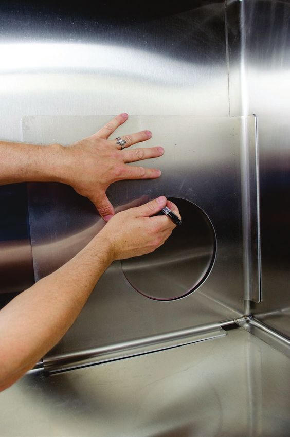
CONTENTS

  INTRODUCTION
      Introduction .................................................................................................. ii
  GENERAL INFORMATION
      General information .....................................................................................1
      Safety Alert Symbol ............................................................................................................ 1
      Personal Protective Equipment (PPE)................................................................................ 1
      Safety Warnings Included In This Guide ............................................................................ 2
  SECTION ONE, PRE-ASSEMBLY
      Shipment Inventory And Inspection .............................................................3
         Shipment Inventory....................................................................................................... 3
         Shipment Inspection ..................................................................................................... 3
         Damage Reporting........................................................................................................ 3
      Hole Template..................................................................................................................... 3
      Parts List............................................................................................................................. 4
      Tools And Equipment.......................................................................................................... 5
  SECTION TWO, ASSEMBLY PROCEDURES
      Assembly Procedures..................................................................................6
      Cage Preparation ............................................................................................................... 6
         Portal Location.............................................................................................................. 6
         Cage Door Removal ..................................................................................................... 7
      Portal Hole.......................................................................................................................... 8
         Template ....................................................................................................................... 8
         Mark/Punch Starter Hole .............................................................................................. 9
         Drill Starter Hole ......................................................................................................... 10
         Portal Hole Cut ........................................................................................................... 10
      Portal Installation .............................................................................................................. 12
         Spacer Installation ...................................................................................................... 12
         Flange Components Installation ................................................................................. 13
         Door Installation.......................................................................................................... 14

  SECTION THREE, OPERATION & MAINTENANCE
      Portal Use And Care ..................................................................................16
      Door Operation ................................................................................................................. 16
         Opening and Closing the Portal Door ......................................................................... 16
         Cage Door Realignment (If required).......................................................................... 16
      General Maintenance & Care ........................................................................................... 17
         Maintenance Recommendations ................................................................................ 17
         Care Recommendations ............................................................................................ 17

  SECTION FOUR, TERMS & CONDITIONS
      Terms And Conditions................................................................................18
      Damaged Freight Procedures .......................................................................................... 18
       Limited Warranty ......................................................................................20
           Limitation Of Liability................................................................................................... 20
      Contact Information ...................................................................................21

Shor-Line.com                                                                                                                                     iii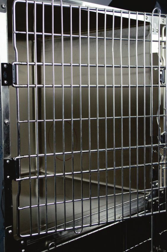
SAFETY
                  GENERAL INFORMATION
    General information
       Refer to the Guide, images and content to assist with the installation of the product.
       Throughout the Guide, safety notices provide help for a successful installation.

                                     SAFETY FIRST!
       Shor-Line uses the following symbols and signal words to identify potential hazards or
       unsafe practices:
    Safety Alert Symbol
              Indicates a potential personal injury hazard exists. It is important to heed any safety
              warning information associated with this alert symbol.
    Signal Words for Hazard Alerting Safety Messages
              Indicates a hazardous situation which, if not avoided, WILL result in serious injury
              or death.
              Indicates a hazardous situation which, if not avoided, COULD result in serious injury
              or death.
              Indicates a hazardous situation which, if not avoided, COULD result in minor or
              moderate injury.
    Important Information Symbol
              Indicates information considered important but not directly hazard related.

    Personal Protective Equipment (PPE)
       PPE refers to protective clothing or other equipment designed to protect against injury. It
       is the responsibility of the client/installer to ensure all local and federal codes are adhered
       to during the installation and assembly of this product. Included is a list of PPE items
       suggested, but not limited to, protective equipment to help complete the installation safely.
             • Eye protection                        • Gloves
             • Metatarsal, foot protection           • Back Support Brace
             • Ear protection

       SHOR-LINE makes no guarantee, implied or otherwise, that the information included in
       this Guide will be complete or failsafe, or that the information will prevent an injury from
       RFFXUULQJ6WDQGDUGPHDVXUHVGHVFULEHGPD\QRWUHÀHFWWKHIXOOH[WHQWRIDOOVWHSVWKDWPD\
       need to be taken in any given emergency instance.

                                California Proposition 65 Warning
                                      This product can expose you to chemicals
                                      including chromium, which are known to the
                                      state of California to cause cancer. For more
                                      information go to: www.P65Warnings.ca.gov

1                                                                                         Shor-Line.com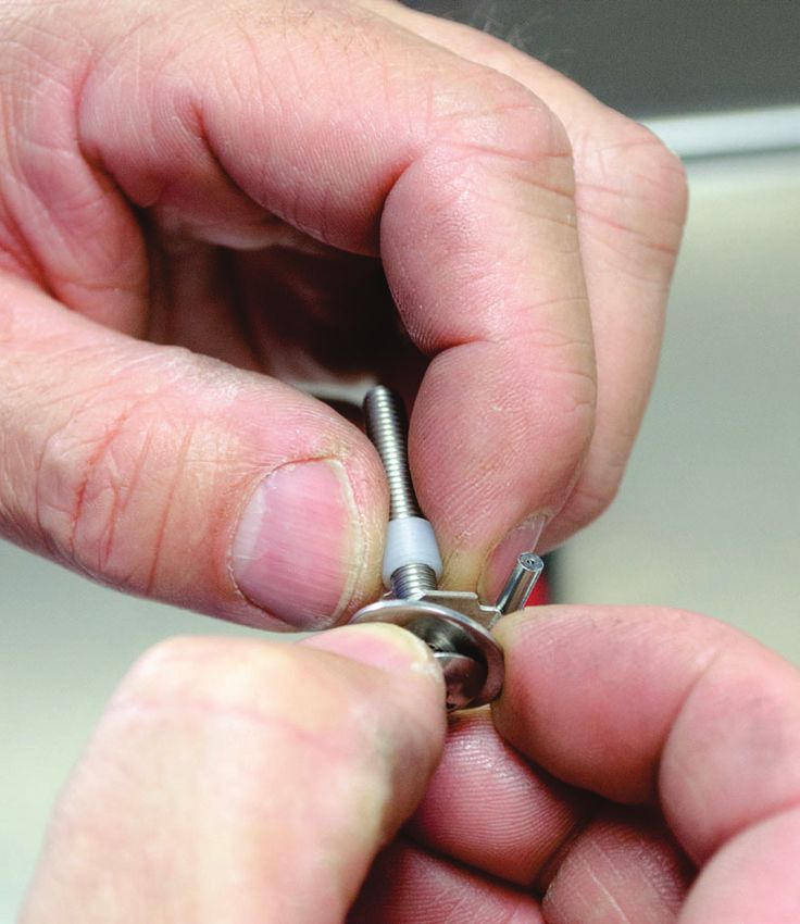
SAFETY

   Safety Warnings Included In This Guide
                READ THIS GUIDE COMPLETELY BEFORE INSTALLATION AND USE AND
                THOROUGHLY UNDERSTAND AND FOLLOW ALL SAFETY INSTRUCTIONS.
                DO NOT use a plasma cutter to cut the Portal hole. Plasma cutters can create excessive
                KHDWWKDWFDQUHVXOWLQVHYHUHEXUQVRU¿UHZKLFKZLOOFDXVH6(5,2863(5621$/
                INJURY OR DEATH.
                PRIOR TO DRILLING OR CUTTING A CAGE PANEL, ALWAYS INSPECT the space
                between the cage panels to be sure there are no electrical wires or other obstructions
                present. Cutting into live wires or other obstructions can result in electrical shock
                which will cause SERIOUS PERSONAL INJURY OR DEATH or property damage.
                Installation of the Portal MUST BE COMPLETED BY A QUALIFIED INSTALLER familiar
                ZLWKVKHHWPHWDOPDQLSXODWLRQPRGL¿FDWLRQV&XWWLQJRUGULOOLQJLQWRPHWDOFDJHVFDQ
                produce sharp or jagged edges which could cause serious lacerations which, if not
                avoided, could result in SERIOUS INJURY OR DEATH.
                Stay clear of and DO NOT TOUCH exposed cut steel. Cutting or drilling into metal cages
                can produce sharp or jagged edges which could cause serious lacerations which, if not
                avoided, could result in SERIOUS INJURY OR DEATH.
                Stainless steel cages are heavy. Enlist help and USE SAFE LIFTING PRACTICES when
                removing any cages from or placing cages back into the cage bank to avoid risk of
                SERIOUS INJURY OR DEATH.
                WEAR PERSONAL PROTECTIVE EQUIPMENT, such as, but not limited to, eye
                protection, ear protection, and gloves during installation. Failure to do so could result
                in SERIOUS INJURY OR DEATH.
                This product is intended to be used for animals only. Do not use for anything other than
                the intended purpose.
                %HVXUHWRVHFXUHORQJKDLURUORRVH¿WWLQJFORWKLQJGXULQJLQVWDOODWLRQ/RQJKDLURU
                ORRVH¿WWLQJFORWKLQJFDQEHFRPHHQVQDUHGRQH[SRVHG FXW VWDLQOHVVVWHHOHGJHVDQG
                cutting tools, and if not avoided, could result in minor or moderate injury.
                Keep hands clear of possible pinch areas when moving parts, which if not avoided,
                could result in minor to moderate injury.
                SHOR-LINE is not responsible for replacing mis-cut or damaged cages.
                During cleaning and maintenance, DO NOT pull the Portal Door away from the cage
                wall. Injury or damage to property could occur.

Shor-Line.com                                                                                               2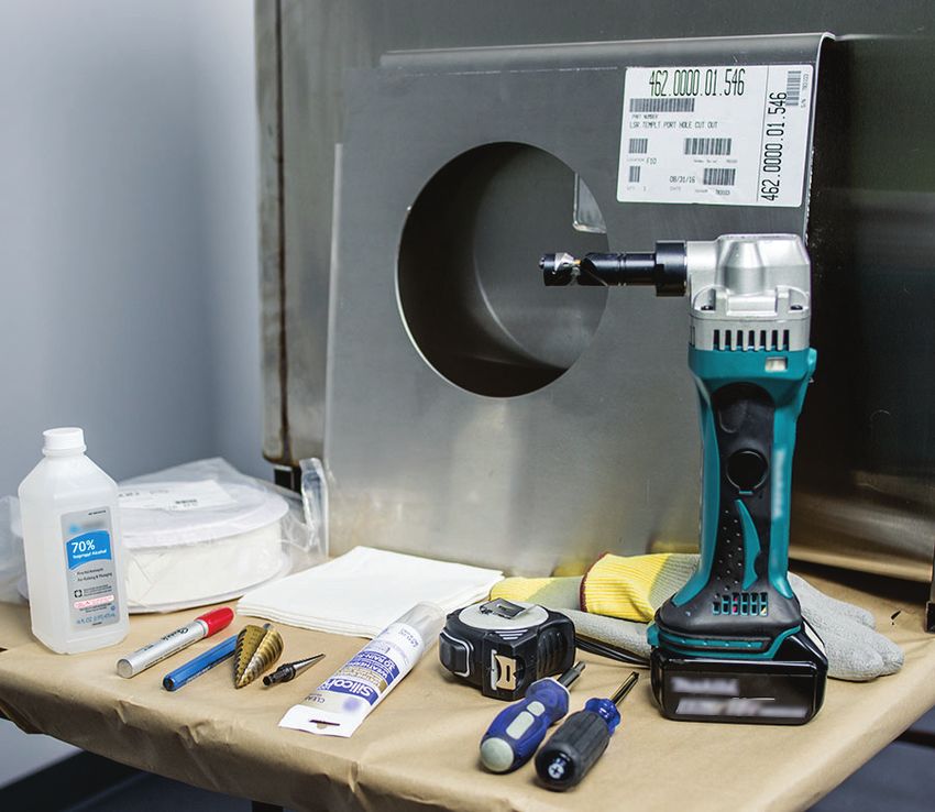
ONE
SECTION ONE, PRE-ASSEMBLY
SECTION
Shipment Inventory And Inspection
Shipment Inventory
At arrival, unpack and inspect the shipment to ensure it is complete and free of damages
that may have occurred during shipping. Compare the packing list with the shipment to
ensure all parts/components have been received in good condition. See FIGURES 1.1-1.2
Avoid using razor blade or cutting devices, product surfaces scratch easily.
Shipment Inspection
While verifying the shipment contents, take a moment to inspect each component for
damage. This should be done before the shipment is signed received and accepted. If
damaged components are apparent, follow the claim procedures set forth by the carrier.
Damage Reporting
Follow the instructions within Shor-Line’s Damage and Freight Procedures. Contact Shor-
Line (800.444.1579) immediately to expedite the process.
$IWHU¿IWHHQ FDOHQGDUGD\VRIUHFHLSWRIPHUFKDQGLVHWKLVSROLF\EHFRPHVYRLG
Hole Template
The SHOR-LINE Portal comes complete with the
portal components, spacer, and hardware required to
complete the installation. The two cages that are to
EHOLQNHGXVLQJWKH3RUWDOZLOOKDYHWREHPRGL¿HGWR
receive the Portal.
The Portal does NOT include the hole Template
unless it was ordered at the time of purchase.
A .125" thick aluminum plate hole Template is
available and can be ordered to assist locating the
proposed holes in each cage. See FIGURE 1.1
The Template is useful and durable; the same
Template can be reused for each Portal installation. FIGURE 1.1 - Template (Kat Portal Shown)
It is important to locate the proposed holes perfectly aligned to each other in each
cage. The Template insures consistent location on both the left and right cages.
SHOR-LINE is not responsible for replacing mis-cut or damaged cages.
PORTAL TEMPLATES
PART # DESCRIPTION OPENING HOLE CENTER
300.2229.00 Kat Portal Hole Template - Aluminum Plate 8.5" Diameter 7[ٺM\.ZWU*W\\WUIVL*IKS8IVMT[
300.2334.00 Puppy Portal Hole Template - Aluminum Plate 12.5" Diameter *W\\WU@! *IKS
3 Shor-Line.com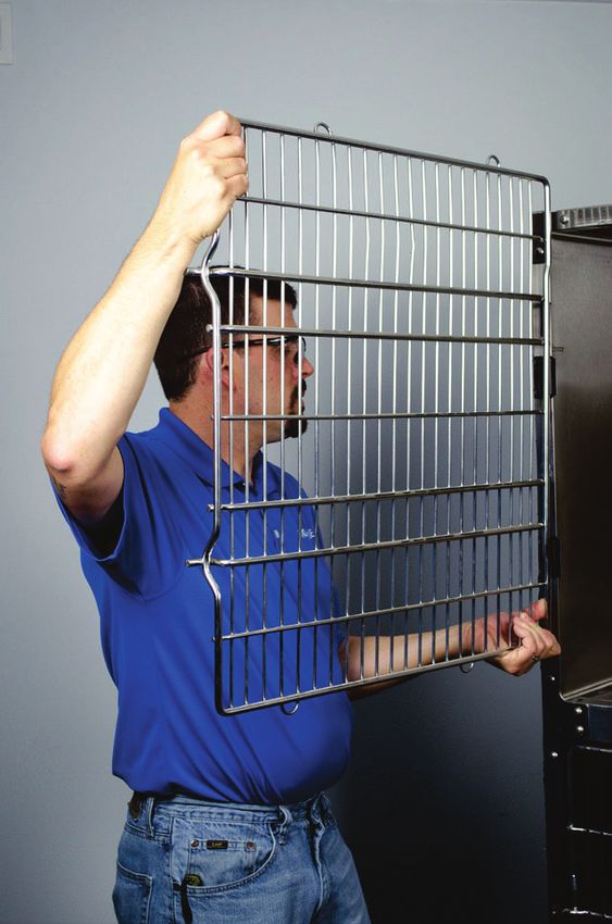
SECTION ONE
Parts List
04 01
02
05
03
09
07
06
08
10
FIGURE 1.2 - Portal Assembly (Kat Portal Shown)
PORTAL ASSEMBLY CONTENTS
ITEM PART # DESCRIPTION QTY Ƒ
902.0000.30 3I\8WZ\IT;\IVLIZL5WLMT;MM+WV\MV\[*MTW_
01 8WZ\IT.MUITM.TIVOM5IZSML * 1 Ƒ
02 8WZ\IT5ITM.TIVOM5IZSML ) 1 Ƒ
03 • Portal - Door Panel 1 Ƒ
04 • 181.9020.06 3I\8WZ\IT;\IVLIZL5WLMT ?QLM;XIKMZ;\aTM[>IZa 1 Ƒ
• 802.0000.25 0IZL_IZM3Q\;MM+WV\MV\[*MTW_
05
`8IV0L8PQTTQX[0Q4W;\IQVTM[[;\MMT 2 Ƒ
06 `
IZa
902.0000.34 8]XXa8WZ\IT?QLM5WLMT
_QLM`
\ITT ?QLM /IX+IOM
;XIKMZ+][\WUMZ8ZW^QLML
Shor-Line.com 4
SECTION ONE

    Tools And Equipment
         Tools and equipment required to complete the installation can vary depending on the task at
         hand and type of construction method employed. Below is a list of tools and equipment used
         in the installation procedures outlined in this Guide. Techniques may vary.
                Installation of the Portal MUST BE COMPLETED BY A QUALIFIED INSTALLER familiar
                ZLWKVKHHWPHWDOPDQLSXODWLRQPRGL¿FDWLRQV&XWWLQJRUGULOOLQJLQWRPHWDOFDJHVFDQ
                produce sharp or jagged edges which could cause serious lacerations which, if not
                avoided, could result in SERIOUS INJURY OR DEATH.

                     TOOLS LIST
    ITEM               DESCRIPTION
    01     5-);=:16/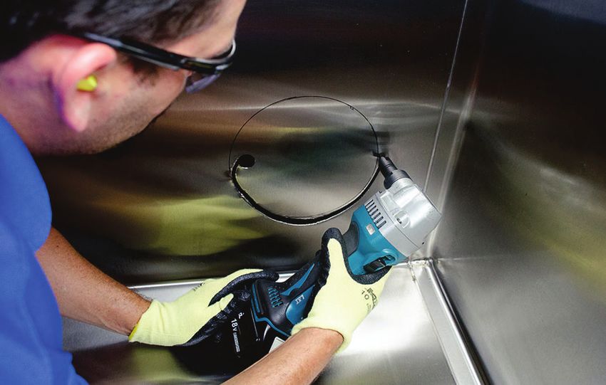
TWO

                                                                                     SECTION
       SECTION TWO, ASSEMBLY PROCEDURES
                                    RE
                                     E
  Assembly Procedures
   Cage Preparation
     Portal Location
      The following instructions include the steps and precautions to install one portal between
      two cages that are a part of a cage bank. Repeat the procedures for each portal installation.
                Installation of the Portal MUST BE COMPLETED BY A QUALIFIED INSTALLER familiar
                ZLWKVKHHWPHWDOPDQLSXODWLRQPRGL¿FDWLRQV&XWWLQJRUGULOOLQJLQWRPHWDOFDJHVFDQ
                produce sharp or jagged edges which could cause serious lacerations which, if not
                avoided, could result in SERIOUS INJURY OR DEATH.
      The template can be used to mark the portal hole location from the inside of the cage and
      can also be used to locate the holes from the outside of the cage. Depending on the size of
      the proposed cages, it may be determined that hole placement and cutting may be easier
      from the outside of the cage. The trim plates (#3 phillips head screwdriver) will have to be
      removed and the cages will have to be removed from the bank for this type of installation.
                Stainless steel cages are heavy. Enlist help and USE SAFE LIFTING PRACTICES when
                removing any cages from or placing cages back into the cage bank to avoid risk of
                SERIOUS INJURY OR DEATH.
      Any cages removed during the hole cutting process will have to be reinstalled in the cage
      bank before continuing with the Portal installation.
      )RUWKHSXUSRVHRIWKHVHLQVWUXFWLRQVHDFKFDJHZLOOKDYHDXQLTXHLGHQWL¿HUWKHFDJHRQWKH
      right is "CAGE ONE" and the cage on the left is considered "CAGE TWO". See FIGURE 2.1

                                                        CAGE              CAGE
                                                        TWO                ONE

                              .1/=:-+IOM1LMV\QÅKI\QWV-`IUXTM

Shor-Line.com                                                                                           6
SECTION TWO

     Cage Door Removal
      Door hinges may vary depending on the release model of the cages. Type III cages
      are used for this procedure. Contact SHOR-LINE for door removal procedures for older
      model cages.
       STEP 1: Ensure both proposed cages are cleared of animals, bedding, and are
                thoroughly clean.
       STEP 2: Remove the door from the cage.
             A: Unlatch and swing door to the open position (90 degrees). See FIGURE 2.2
             Keep hands clear of possible pinch areas when moving parts, which if not avoided,
             could result in minor to moderate injury.
             B: Lift the door upward and slide the door from the hinges. Set away from the work
                area. See FIGURE 2.3
       STEP 3: 5HSHDWWKHGRRUUHPRYDOVWHSVIRUHDFKFDJHWREH¿WWHGZLWKDSRUWDO

              FIGURE 2.2 - Cage Door Removal         FIGURE 2.3 - Cage Door Removal

7                                                                                    Shor-Line.com
SECTION TWO
Portal Hole
Template
The portal holes can be cut with the cages located in a bank or as a stand-alone cage. For
the purpose of this Guide, instruction included will describe the steps required to cut the
portal holes with the cages located within a bank of cages.
Installation of the Portal MUST BE COMPLETED BY A QUALIFIED INSTALLER familiar
ZLWKVKHHWPHWDOPDQLSXODWLRQPRGL¿FDWLRQV&XWWLQJRUGULOOLQJLQWRPHWDOFDJHVFDQ
produce sharp or jagged edges which could cause serious lacerations which, if not
avoided, could result in SERIOUS INJURY OR DEATH.
$OORZLQJWKHFXWWLQJWRROWRUXQR௺OLQHZLOOFDXVHLUUHSDUDEOHGDPDJHWRWKHFDJH
SHOR-LINE is not responsible for replacing mis-cut or damaged cages.
The template and a marker will be used to located
a hole in the side walls of the two cages that are to
receive the Portal.
The center-mark for the 8.5" cat portal hole is 8-3/8"
from the bottom panel and from the back panel.
The center-mark for the 12.5" puppy portal hole is
8-3/8" from the bottom panel and 9-3/8" from the
back panel.
STEP 4: Gently move the template into CAGE ONE,
UHVWLQJWKHEHQWDOXPLQXP ÀDQJH DJDLQVW
the side and back panels. See FIGURE 2.4 FIGURE 2.4 - Template
STEP 5: Move the template down and rest against the bottom and back panels. The radius
RIWKHÀDQJHVPDWFKWKHUDGLXVRIWKHFDJHIRUDVQXJ¿W
STEP 6: Once the template is in place, mark the
side panel using the template as a guide
for the hole location. See FIGURE 2.5
STEP 7: Remove the template, careful not to
smudge the hole marking or scratch the
cage surface.
STEP 8: The template will have to be rotated to rest in
CAGE TWO. Insert the template and mark
the hole location following the same steps
used to locate the hole for CAGE ONE.
FIGURE 2.5 - Template
Shor-Line.com 8SECTION TWO
Mark/Punch Starter Hole
A hammer, punch, drill, step hole drill bits, and cleaning
supplies will be used to create a starter hole. This hole
will be the start point for the Nibbler cutting tool, the
KROHPXVWEHODUJHHQRXJKWR¿WWKHFXWWLQJKHDGRIWKH
Nibbler to begin the cut.
Location of the hole will vary depending on model/size
of the Nibbler used to cut the portal hole.
STEP 9: Dry run: Hold the Nibbler along the cutting
line to ensure there is enough clearance to
fully rotate the cutting tool without making
contact with the back and bottom panels.
See FIGURE 2.6
STEP 10: Establish a comfortable starting point,
where the Nibbler will be able to rotate
around the hole clearing the back and
bottom panels.
STEP 11: Mark a punch location within the portal .1/=:-
SECTION TWO

     Drill Starter Hole
      A starter hole will have to be drilled in order to insert (start) the Nibbler. Take care to ensure
      the starter hole does not encroach or expand past the portal hole outline.
                PRIOR TO DRILLING OR CUTTING A CAGE PANEL, ALWAYS INSPECT the space
                between the cage panels to be sure there are no electrical wires or other obstructions
                present. Cutting into live wires or other obstructions can result in electrical shock
                which will cause SERIOUS PERSONAL INJURY OR DEATH or property damage.
                The punched indention helps center the drill bit in place. Care should be taken when
                drilling holes in steel, as the drill bit can release from the punched indention and
                scratch the cage surface.
       STEP 13: Use a power drill and a 1/4" drill bit to start a hole at a size that will accept a step
                   drill bit. See FIGURE 2.10

                   FIGURE 2.10 - Starter Hole               FIGURE 2.11 - Step Drill
       STEP 14: Use a power drill and step drill bit to increase the hole to a size that will accept
                   the cutting head (Up to 7/8"). See FIGURE 2.11
       STEP 15: Remove metal shavings and clean the cage of debris.
     Portal Hole Cut
                DO NOT use a plasma cutter to cut the Portal hole. Plasma cutters can create excessive
                KHDWWKDWFDQUHVXOWLQVHYHUHEXUQVRU¿UHZKLFKZLOOFDXVH6(5,2863(5621$/
                INJURY OR DEATH.
                PRIOR TO DRILLING OR CUTTING A CAGE PANEL, ALWAYS INSPECT the space
                between the cage panels to be sure there are no electrical wires or other obstructions
                present. Cutting into live wires or other obstructions can result in electrical shock
                which will cause SERIOUS PERSONAL INJURY OR DEATH or property damage.
                Installation of the Portal MUST BE COMPLETED BY A QUALIFIED INSTALLER familiar
                ZLWKVKHHWPHWDOPDQLSXODWLRQPRGL¿FDWLRQV&XWWLQJRUGULOOLQJLQWRPHWDOFDJHVFDQ
                produce sharp or jagged edges which could cause serious lacerations which, if not
                avoided, could result in SERIOUS INJURY OR DEATH.

Shor-Line.com                                                                                            10
SECTION TWO
There are several techniques (tools) that can be used
to cut a hole in stainless steel. For the purpose of this
Guide, instruction included will describe the steps
required to cut the portal holes with a Nibbler using a
11/16" cutting head. BIT CUT
DIRECTION
*
The cutting head will have to be locked into place,
perpendicular to the handle of the Nibbler. "Free"
and straight cutting positions could cause clearance PIVOT
issues due to the location of the hole and its proximity
to the back and bottom panels of the cage. See
FIGURE 2.12 FIGURE 2.12 - Nibbler Rotation
STEP 16: Insert the cutting head into the hole and locate a starting point to begin the cut.
See FIGURE 2.13
FIGURE 2.13 - Start Cut FIGURE 2.14 - Rotate Nibbler
STOP cutting, realign at any point during the cut if the cutting head strays from the hole
JXLGHOLQH0LVFXWVFDQGDPDJHWKHFDJHDQGD௺HFWWKHVHDORIWKHSRUWDO
STEP 17: Rotate the Nibbler as it cuts the steel, following the hole guide line.
See FIGURE 2.13 to 2.16
FIGURE 2.15 - Rotate Nibbler FIGURE 2.16 - Rotate Nibbler
STEP 18: %HQG¿OHDQ\HGJHVXUIDFHVSURWUXGLQJIURPWKHSDQHO
ZDOOWKDWFRXOGDႇHFWWKHVHDO6HH)IGURE 2.17
STEP 19: Remove metal shavings and clean the cage of debris.
FIGURE 2.17 - Hole
11 Shor-Line.comSECTION TWO
Portal Installation
Spacer Installation
Stage the Flange A in Cage TWO and the Flange B in Cage ONE. To discern between
components, the Flange A has mounting holes on the trim face. See FIGURES 2.18
and 2.19
FIGURE 2.18 - Flange A FIGURE 2.19 - Flange B
7KHÀDQJHFRPSRQHQWVZLOOEHLQVHUWHGIROORZLQJWKHVSDFHULQVWDOODWLRQDQGVKRXOGEH
staged in each cage, within reach. See FIGURE 2.20
CAGE CAGE
TWO ONE
FIGURE 2.20 - Flange Staging .1/=:-;XIKMZ
The spacer provides support between the cage walls to help prevent wall panel movement.
The diameter of the spacer is larger than the portal hole. The spacer has a split seam which,
when the two ends of the ring are collapsed can rest on each other reducing the diameter,
enabling the spacer to be inserted into the hole. See FIGURE 2.21
STEP 20: Collapse one end of the spacer ring inside the other. See FIGURE 2.21
STEP 21: Insert the spacer ring in-between the two cages. HOLD IN PLACE. See
FIGURE 2.22 & 2.23
.1/=:-;XIKMZ1V[MZ\QWV .1/=:-;XIKMZ1V[\ITTML
Shor-Line.com 12SECTION TWO
Flange Components Installation
STEP 22: Add a 1/4" continuous bead of clear
VLOLFRQHWRWKHLQVLGHRIHDFKÀDQJH5HDG
and follow the manufacturers instructions for
silicone application. See FIGURE 2.24
STEP 23: &DUHIXOO\URWDWHWKHÀDQJHVWRHQVXUHWKH
attachment holes are parallel to the cage
ÀRRU6HH),*85(
STEP 24: ,QVHUWWKHIHPDOHÀDQJHFRPSRQHQW
through the hole/spacer. The arrow and
QRWFKRQWKHÀDQJHVKRXOGSRLQWXSZDUG .1/=:-
;QTQKWVM)XXTQKI\QWV
See FIGURE 2.26
STEP 25: ,QVHUWWKHPDOHÀDQJHFRPSRQHQWLQVLGHWKHIHPDOHÀDQJHFRPSRQHQWWKHDUURZ
VKRUOLQHORJRDQGQRWFKRQWKHÀDQJHVKRXOGEHLQWKHXSZDUGSRVLWLRQ6HH
FIGURE 2.27
&DUHIXOO\URWDWHWKHÀDQJHVWR
ensure the attachment holes
DUHSDUDOOHOWRWKHFDJHÀRRU
EQUAL DISTANCE
EQUAL DISTANCE
.1/=:-
+WVVMK\QWV FIGURE 2.26 - Female Flange FIGURE 2.27 - Male Flange
STEP 26: 8VHWZR;3$1+'SKLOOLSVVFUHZVWRVHFXUHWKHWZRÀDQJHVWRJHWKHU7KH
VFUHZVWKUHDGLQWRWKHSODVWLFÀDQJH6HH),*85(
STEP 27: :LSHFOHDQDQ\VLOLFRQHWKDWKDVRR]HGRXWEHWZHHQWKHÀDQJHDQGFDJHZDOO
See FIGURE 2.29
Do NOT over-tighten the screws, damage to the components could occur.
.1/=:- ;MK]ZM.TIVOM[ FIGURE 2.29 - Clean Portal
13 Shor-Line.comSECTION TWO
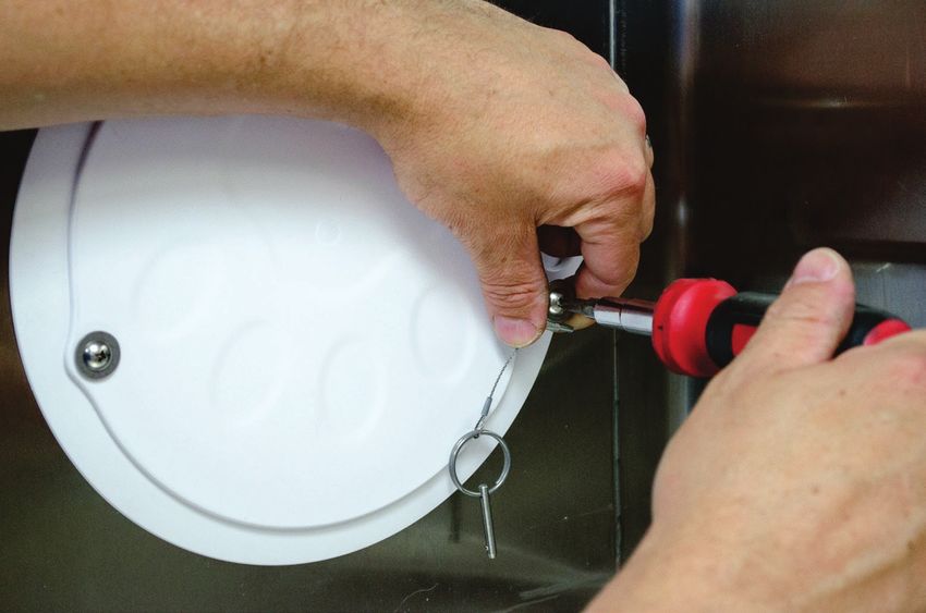
Door Installation
The portal door is secured with one screw on the hinge side, and one screw on the door
stop side. the door is in the closed position when the paw is facing down, inversely, the paw
is facing up when the door is in the open position. See FIGURE 2.30 and FIGURE 2.31
FIGURE 2.30 - Door Closed Position FIGURE 2.31 - Door Open Position
See FIGURE 1.2 to help identify each piece of hardware used for the door installation.
It is important to install all hardware in the correct order for the Door to operate
correctly. Do NOT over-tighten screws, damage to the components could occur. Refer
WRWKHSDUWVOLVW ),*85( IRUKDUGZDUHDVVHPEO\RUGHU7KHVKRUW1\ORQ6SDFHUVDUH
used for the Kat Portal and the long Nylon Spacers are used for the Puppy Portal.
STEP 28: Use one (1) of the phillips screws, one
ÀDWZDVKHUWKHZDYHZDVKHUDQGRQH
Q\ORQVWDQGRႇVSDFHUWRVHFXUHWKH
hinge side of door. See FIGURE 2.32
STEP 29: Tighten the hinge screw just tight
enough to provide tension on the door.
rotate the door to the open position to
ensure free movement, yet the door
hinge screw should be tight enough to
hold the door in any position. FIGURE 2.32 - Door Hinge Assembly
Shor-Line.com 14SECTION TWO
STEP 30: Use one (1) of the phillips screws, one (1)
ÀDWZDVKHUTXLFNUHOHDVHSLQDVVHPEO\
DQGRQH Q\ORQVWDQGRႇVSDFHUWR
secure the door stop side of door. See
FIGURE 2.33
The screw is threaded into the male
ÀDQJHDQGGRHV127JRWKURXJKWKHGRRU
The short nylon spacers are used for the
Kat Portal and the long nylon spacers are
used for the Puppy Portals.
5HIHUWRWKHSDUWVOLVW ),*85( IRUKDUGZDUH
assembly order.
STEP 31: With the door in the closed position,
paw down, the quick release pin can
be inserted into the hole to secure the
door closed. See FIGURE 2.34 .1/=:-9]QKS:MTMI[M)[[MUJTa
STEP 32: Thoroughly clean both cages and the portal to ensure the removal of all
chemicals and metal shavings before allowing the cages to become occupied.
STEP 33: Reverse STEP-2 procedures to reinstall the cage doors.
STEP 34: Close the doors, check latch operation and adjust alignment to ensure the doors
latch correctly.
.1/=:-
;MK]ZM,WWZ
15 Shor-Line.comTHREE
SECTION
SECTION THREE, OPERATION & MAINTENANCE
NTENANCE
Portal Use And Care
Door Operation
Opening and Closing the Portal Door
Once the Portal is installed, the door can be used to control access to one cage
or the other by rotating the door to the closed or open position, as desired.
PAW DOWN PAW UP
CLOSED OPEN
FIGURE 3.1 - Door Closed Position FIGURE 3.2 - Door Open Position
The door is in the closed position when the paw is LOCK HOLE
facing down. Inversely the paw is facing up when the
door is in the open position. See FIGURE 3.1 and
FIGURE 3.2
A pin is provided to lock the door in the closed position.
Remove the pin from the stowed position, close the LOCK PIN
door and insert the pin through the Lock Hole. See
FIGURE 3.3
.1/=:-,WWZ4WKS
Cage Door Realignment (If required)
The cage door, after shipment/movement and through regular use can become askew
and require minor adjustments from time to time. If weight is applied to an open door it
may cause the latch pins to come into contact with the latch guides either too high or too
low to properly slide into the latch assembly.
While the cage door is shut and latched, loosen but do
LATCH
not remove the hinge assembly screws.
With one hand holding the door on the latch-side, align LATCH
PIN
the latch pin within the optimal range while tightening OPTIMAL
the hinge screws to hold the door in place.
RANGE
Close the door, check latch operation and make
adjustments to ensure the door latches correctly.
.1/=:-
4I\KP)TQOVUMV\
Shor-Line.com 16SECTION THREE
General Maintenance & Care
Maintenance Recommendations
Routine maintenance will extend the quality and life of Shor-Line products.
It is the owners responsibility to set-up scheduled maintenance programs, depending on
use of the equipment. Scheduled preventive maintenance should include, but not limited
to daily or weekly inspections and maintenance of products to prolong its longevity and
to help maintain proper product functions.
• Follow manufacturers cleaning and maintenance recommendations outlined in product literature
SURYLGHGIRUFRPSRQHQWVQRWLQFOXGHGLQWKHVHUHFRPPHQGDWLRQV&RQ¿JXUDWLRQVFRPSRQHQWSDUWV
may vary.
• Check alignment of operable panels, doors and components to ensure operation is free of
obstructions. Adjust as required.
• Check any battery compartments to ensure the batteries are not failing, corroding the
contacts or damaging the equipment. A pencil eraser can be used to clean electrical contacts
in battery compartments.
• Check any wiring for kinks or exposed inner wiring. If damage exist, stop equipment use and
contact Shor-Line Technical Services for direction.
• &KHFNDQ\K\GUDXOLFOLIWFRPSRQHQWVIRUOHDNLQJÀXLG,IÀXLGLVSUHVHQWVWRSHTXLSPHQWXVHDQG
contact Shor-Line Technical Services for direction. Do NOT attempt to repair hydraulic leaks.
Care Recommendations
Routine product care will extend the quality and life of Shor-Line products and aids in
protecting animals from transmittable diseases and infections.
It is the owners responsibility to set-up scheduled cleaning programs, depending on
use of the equipment. Scheduled preventive cleaning should include, but not limited to
daily or weekly inspections and cleaning of products to prolong its longevity and to help
PDLQWDLQ¿QLVKHV
Safe Cleaning Practices
• 8VHWKHPLOGHVWFOHDQLQJSURFHGXUHWKDWZLOOFRPSOHWHWKHMREHႇHFWLYHO\2UGLQDU\ZDVWHGHSRVLWV
DQGÀXLGVFDQXVXDOO\EHUHPRYHGZLWKVRDSDQGZDWHUXVLQJDVRIWFORWKRUVSRQJH5LQVH
thoroughly with clear water and dry completely with a soft cloth to discourage hard-water spotting.
• Minor scale build up and some hard water spotting can be removed by washing with a vinegar
diluted mixture followed by a clear water rinse and thorough drying.
• Bleach, deodorizing agents, disinfectants, and sanitizers can corrode stainless steel, thoroughly
rinse all surfaces treated with these chemicals with a clear water rinse and dry with a soft cloth.
• ,IVFUXEELQJLVUHTXLUHGXVHRQO\SRO\PHURUQ\ORQ¿EHUSURGXFWVPDGHIRUXVHZLWKSRO\PHURU
nylon materials.
• Always rinse with clear water and dry of all surfaces treated with cleaning, sterilization solutions.
Unsafe Cleaning Practices (NOT Recommended)
• Do NOT use a dry cloth or wipe clear polymer surfaces which can scratch if dust/dirt is wiped with
the hand or dry cloth.
• Polymer materials can discolor if exposed to sunlight, ultraviolet rays. Avoid direct sun exposure.
• Do NOT use ammonia or bleaches to clean polymer surfaces.
• 'R127DOORZÀXLGVWRDFFXPXODWHSXGGOHZLWKRXWUHPRYLQJDQGFRPSOHWHO\GU\LQJWKH
VXUIDFHVDQGFRPSRQHQWV6WDQGLQJZDWHUÀXLGVDUHDKD]DUGDQGFDQFDXVHGDPDJHWR
component materials.
• 'R127XVHVFRXULQJSRZGHUVWKDWZLOOVFUDWFKSRO\PHU¿QLVKHV
Steel wool or steel brushes should never be used to clean stainless steel or polymer
surfaces, avoid abrasive cleaning techniques/supplies.
17 Shor-Line.comFOUR
SECTION
SECTION FOUR, TERMS & CONDITIONS
ONS
Terms And Conditions
Shor-Line's TERMS AND CONDITIONS can be found at shor-line.com
m
Damaged Freight Procedures
Freight Claim - Contact the technical services department toll-free at 1.800.444.1579
7R¿OHDIUHLJKWFODLP
Inspect ALL packages upon arrival. If containers show evidence of damage when delivered,
the packages should be opened and inspected before the carrier leaves. The shipment
should be inventoried and inspected jointly by the customer and the carrier. The driver will
then make proper notation on the delivery receipt.
Customer must inspect all materials for shortages, damages, conformity with the order,
and defects before signing any documentation requested by the carrier. Customer
must immediately complete such inspection and shall not accept delivery of goods that
are damaged or not in accordance with the bill of lading or packing slip without proper
QRWL¿FDWLRQWRWKHFDUULHUDQG6KRU/LQH,ISURGXFWVDUHGDPDJHGGHIHFWLYHVKRUWHGRU
appear not to conform to the order, Customer shall discontinue their use and immediately
QRWLI\WKHFDUULHUDQG6KRU/LQHRIVXFKFRQGLWLRQDQGDႇRUGDUHDVRQDEOHRSSRUWXQLW\WR
inspect the same.
Customer shall make, or provide Shor-Line in writing with all information necessary to make
a claim against such carrier for any shortage, damage, or discrepancy of the shipment
ZLWKLQ¿IWHHQ GD\VDIWHUUHFHLSWRIWKHSURGXFWV&ODLPVRUZULWWHQLQIRUPDWLRQWKHUHRQ
QRWVRSUHVHQWHGZLWKLQ¿IWHHQ GD\VDIWHUUHFHLSWRIWKHSURGXFWVZLOOQRWEHDOORZHG
No returned products will be accepted, credited or replaced, unless arrangements for their
return have been made in compliance with Shor-Line's Return Policy.
If containers do not show evidence of damage, there may be "concealed damage".
Customer must report any concealed damage within 15 days after receipt of the shipment.
6XFKUHSRUWLVWREHPDGHGLUHFWO\WR6KRU/LQH V7UDႈF'HSDUWPHQWZKRZLOO¿OHDFODLPZLWK
the carrier. All packaging and contents must be held for this inspection.
STEP 1: Customer must check goods, contents against packing slip, weight against bill of lading,
containers, etc.
STEP 2: &XVWRPHU¿OOVRXW,QVSHFWLRQ5HSRUWRI/RVVRU'DPDJH'LVFRYHUHG$IWHU'HOLYHU\
STEP 3: Customer is to sign the report form. A copy is left with the customer and should be
IRUZDUGHGWR6KRU/LQH VWUDႈFGHSDUWPHQWWR¿OHDFODLP
STEP 4: &DOO6KRU/LQH V7UDႈF'HSDUWPHQWWR¿OHDFODLP
6KRU/LQHZLOO
arrange pick-up, return shipment, and replacement of the product.
Shor-Line.com 18SECTION FOUR
Return Policy & Repairs - All products being returned for any reason or delivered for
repair service (whether or not pursuant to the Limited Warranty) must receive advance
authorization from Shor-Line. Customer must contact Shor-Line's Technical Service
Department at 1.800.444.1579 to receive a Return Authorization Number. All products
returned, except for warranty service or pursuant to the Product Satisfaction policy, are
subject to a minimum 15% restocking charge. Customer will be responsible for all freight
charges on returns.
Return Product Authorization7RDVVXUHHႈFLHQWKDQGOLQJRQGDPDJHGRUGHIHFWLYH
equipment, or repairs, please contact our Technical Service Department for Return Product
Authorization (1.800.444.1579). Failure to obtain Return Product Authorization will only
delay processing and may result in the denial of any repair, replacement or credit.
Repairs - It is mandatory to contact Technical Service Department at 1.800.444.1579 prior
to sending product for repair.
19 Shor-Line.comSECTION FOUR
Limited Warranty
,QWKHHYHQWWKH&XVWRPHULVQRWIXOO\VDWLVÀHGZLWKWKHTXDOLW\RUZRUNPDQVKLSRIDSURGXFW6+25/,1(LQLWVVROH
GLVFUHWLRQPD\DUUDQJHHLWKHUWRFUHGLW&XVWRPHU VDFFRXQW H[FOXGLQJVKLSSLQJDQGKDQGOLQJFRVWV RUUHSODFHWKH
SURGXFW+RZHYHU&XVWRPHUPXVWQRWLI\6+25/,1(LQZULWLQJRILWVGLVVDWLVIDFWLRQZLWKLQÀIWHHQ GD\VRIUHFHLSWRI
WKHSURGXFWIURP6+25/,1(&XVWRPHUPXVWDOVRUHWXUQWKHUHMHFWHGSURGXFWWR6+25/,1( IUHLJKWSDLG ZLWKLQWKLUW\
GD\VRILWVUHFHLSWLQFRPSOLDQFHZLWK6+25/,1( V5HWXUQ3ROLF\ 6HH6HFWLRQ 6+25/,1( VREOLJDWLRQLVOLPLWHG
WRSURYLGLQJWKHDSSOLFDEOHFUHGLWRUSURGXFWUHSODFHPHQWZKLFKZLOOEHSURFHVVHGRQO\DIWHUUHFHLSWRIWKHUHWXUQHG
SURGXFW,QDGGLWLRQWKLV3URGXFW6DWLVIDFWLRQ3ROLF\GRHVQRWDSSO\WRVSHFLDOO\GHVLJQHGGLVFRQWLQXHGXVHGIDFWRU\
VHFRQGRUUHSDLUHGSURGXFWV
6+25/,1(ZDUUDQWVWRWKHLQLWLDOSXUFKDVHURQO\RISURGXFWVPDQXIDFWXUHGE\LWWKDWVXFKSURGXFWVDUHIUHHIURPGHIHFWV
LQPDWHULDOVRUODERUIRUYDU\LQJSHULRGVGHSHQGLQJRQWKHSDUWLFXODUSURGXFWDQGVXEMHFWWRWKHOLPLWDWLRQVDQGFRQGLWLRQV
VHWIRUWKKHUHLQ6+25/,1( VVWDLQOHVVVWHHOSURGXFWVDUHZDUUDQWHGWREHIUHHIURPVXFKGHIHFWVIRUWKHLUQRUPDOXVHIXO
OLIH6+25/,1( VPHFKDQLFDODQGHOHFWULFDOSURGXFWVSDUWVGHYLFHVDQGFRPSRQHQWV LQFOXGLQJVXFKSDUWVGHYLFHV
DQGFRPSRQHQWVRIVWDLQOHVVVWHHOSURGXFWV DQGRWKHUQRQVWDLQOHVVVWHHOSURGXFWVDUHZDUUDQWHGWREHIUHHIURPVXFK
GHIHFWVIRURQH\HDU6+25/,1(GLVFODLPVDQ\H[SUHVVRULPSOLHGZDUUDQW\IRUSURGXFWVQRWPDQXIDFWXUHGE\6+25/,1(
DQGWKHRQO\ZDUUDQW\DYDLODEOHWKHUHIRUWRFXVWRPHULVWKDWRIIHUHGE\WKHSURGXFWV PDQXIDFWXUHUV
7KHZDUUDQW\SHULRGVKDOOUXQIURPWKHGDWHRIGHOLYHU\WRFXVWRPHU,IZLWKLQWKHDSSOLFDEOHZDUUDQW\SHULRGDSURGXFW
SURYHVWREHGHIHFWLYHDVGHVFULEHGKHUHLQ6+25/,1(ZLOOUHSDLURUUHSODFHWKHSURGXFWDW6+25/,1( VVROHGLVFUHWLRQ
FRQGLWLRQDOXSRQFXVWRPHU VZULWWHQQRWLFHRIWKHGHIHFWZLWKLQÀIWHHQ GD\VDIWHULWVGLVFRYHU\DQGFRPSOLDQFH
ZLWKDSSOLFDEOHUHWXUQSURFHGXUHV8SRQUHFHLSWRIFXVWRPHU VQRWLFHLQFOXGLQJVXEVWDQWLDWLRQRIFXVWRPHU VVWDWXVDV
WKHLQLWLDOSXUFKDVHUDQGGHWDLOVRIWKHGHIHFW6+25/,1(VKDOODGYLVHFXVWRPHUZKHWKHULWSODQVWRUHSDLURUUHSODFH
WKHSURGXFW6+25/,1( VREOLJDWLRQLVVROHO\OLPLWHGWRUHSDLURUUHSODFHPHQWRIDGHIHFWLYHSURGXFWDQGLQQRHYHQW
VKDOO6+25/,1(EHOLDEOHIRUWUDQVSRUWDWLRQIURPRUWR6+25/,1( VRIÀFHVRUDQ\RWKHUH[SHQVHZKLFKPD\DULVHLQ
FRQQHFWLRQZLWKWKLVOLPLWHGZDUUDQW\RUWKHDIRUHPHQWLRQHGSURGXFWVDWLVIDFWLRQSROLF\
6+25/,1(PDNHVQRRWKHUZDUUDQW\RUJXDUDQWHHRIDQ\NLQGZKDWVRHYHUZKHWKHUH[SUHVVHGRULPSOLHGVWDWXWRU\RU
RWKHUZLVHLQFOXGLQJEXWQRWOLPLWHGWRLPSOLHGZDUUDQWLHVRIÀWQHVVDQGRUPHUFKDQWDELOLW\7KHDERYHOLPLWHGZDUUDQW\
FRQVWLWXWHV6+25/,1( VRQO\ZDUUDQW\DQGQRSHUVRQRUHQWLW\LVDXWKRUL]HGRQEHKDOIRI6+25/,1(WRPRGLI\RU
H[SDQGXSRQWKHSURYLVLRQVH[SUHVVHGLQWKHOLPLWHGZDUUDQW\VWDWHPHQW6+25/,1( VOLDELOLW\XQGHUWKLVOLPLWHGZDUUDQW\
VKDOOEHOLPLWHGDVSURYLGHGIRUDERYHDQGWKHIRUHJRLQJVKDOOEHWKHFXVWRPHUVVROHUHPHG\DQGUHFRXUVHXQGHUWKLV
FRQWUDFW7KHUHDUHQRZDUUDQWLHVZKLFKH[WHQGEH\RQGWKHGHVFULSWLRQRQWKHIDFHKHUH?RIDQGJRRGVDUHVROGDVLV
6+25/,1( VOLPLWHGZDUUDQW\LVRQO\DYDLODEOHWRWKHLQLWLDOSXUFKDVHURILWVSURGXFWV
&XVWRPHUDJUHHVWRFRPSO\ZLWKDOOLQVWUXFWLRQVDQGVSHFLÀFDWLRQVIXUQLVKHGE\6+25/,1(UHODWLQJWRLQVWDOODWLRQ
FDUHDQGDSSOLFDWLRQRISURGXFWVVROG&XVWRPHUDJUHHVWKDWLWZLOOQRWPRGLI\PLVDSSO\RUPLVXVHVXFKSURGXFWVLQDQ\
PDQQHULQFOXGLQJRQHWKDWZRXOGGHYLDWHIURPWKHSURGXFWV LQWHQGHGXVH$Q\UHSDLUVDOWHUDWLRQVRUVHUYLFHSURYLGHG
E\SDUWLHVRWKHUWKDQ6+25/,1(RULWVDXWKRUL]HGUHSUHVHQWDWLYHPD\YRLGWKLVOLPLWHGZDUUDQW\7KLVOLPLWHGZDUUDQW\
VKDOOQRWDSSO\WRQRUPDOZHDUDQGWHDUGDPDJHFDXVHGE\DFFLGHQWQHJOLJHQFHLPSURSHURSHUDWLRQRUWKHXVHRIWKH
FRUURVLYHPDWHULDO LQFOXGLQJZLWKRXWOLPLWDWLRQEOHDFKVRGLXPK\SRFKORULWH RQVWDLQOHVVVWHHOVXUIDFHV6+25/,1( V
OLPLWHGZDUUDQW\PDGHLQFRQQHFWLRQZLWKWKLVVDOHVKDOOQRWEHHIIHFWLYHDQGVKDOOEHYRLGXQOHVVVXFKJRRGVDUHDSSOLHG
DQGXVHGLQDFFRUGDQFHZLWK6+25/,1( VLQVWUXFWLRQV
Limitation Of Liability
8QGHUQRFLUFXPVWDQFHVVKDOO6+25/,1(EHOLDEOHWREX\HURUDQ\RWKHUSHUVRQIRUDQ\VSHFLDOOLTXLGDWHGLQFLGHQWDO
RUFRQVHTXHQWLDOGDPDJHVLQFOXGLQJZLWKRXWOLPLWDWLRQGDPDJHVEDVHGXSRQORVWJRRGZLOOORVWVDOHVRUSURÀWVZRUN
VWRSSDJHGHOD\SURGXFWIDLOXUHLPSDLUPHQWRIJRRGVRURWKHUZLVHDQGZKHWKHUDULVLQJRXWRIEUHDFKRIZDUUDQW\EUHDFK
RIFRQWUDFWQHJOLJHQFHRURWKHUZLVHDQGLQDQ\FDVH6+25/,1( VOLDELOLW\IRUDQ\DQGDOOORVVHVDQGGDPDJHVVXVWDLQHG
E\EX\HUDQGRWKHUVULVLQJRXWRIRUE\UHDVRQRIWKLVFRQWUDFWVKDOOQRWH[FHHGWKHRULJLQDOSXUFKDVHSULFHRIWKH
SURGXFWVXSRQZKLFKOLDELOLW\LVIRXQGHG,QQRHYHQWVKDOODQ\DFWLRQEHFRPPHQFHGDJDLQVW6+25/,1(PRUHWKDQRQH
\HDUDIWHUWKHFDXVHRIDFWLRQZLWKUHVSHFWWRZKLFKWKHFODLPLVPDGHKDVRFFXUUHG6+25/,1(VKDOOQRWEHUHVSRQVLEOH
IRUH[SHQVHVIRUUHSDLUVQRWPDGHE\6+25/,1(ZLWKRXWWKHSULRUZULWWHQFRQVHQWRI6+25(/,1(3URGXFWVSHFLÀFDWLRQV
DUHVXEMHFWWRFKDQJHZLWKRXWDQ\QRWLFHRUREOLJDWLRQRQWKHSDUWRI6+25/,1(
January 2019
Shor-Line.com 20Contact Information
SHOR-LINE SHOR-LINE LIMITED
Schroer Manufacturing Company Vale Business Park Llandow,
511 Osage Ave. Vale of Glamorgan CF71 7PF
Kansas City, Kansas 66105, USA United Kingdom
PHONE: 800.444.1579 PHONE: +44 1446 77 20 41
LOCAL: 913.281.1500 FAX: +44 1446 77 36 68
FAX: 913.281.5339 EMAIL: quality@SHOR-LINE.co.uk
EMAIL: guides@SHOR-LINE.com WEB ADDRESS: SHOR-LINE.co.uk
WEB ADDRESS: SHOR-LINE.com
21 Shor-Line.comYou can also read