Toward a High Performance IPMC Soft Actuator using A disturbance-aided method - arXiv
←
→
Page content transcription
If your browser does not render page correctly, please read the page content below
1

 Toward a High‐Performance IPMC Soft Actuator
 using A disturbance-aided method
 Mohsen Annabestani*, Mohammad Hossein Sayad, Pouria Esmaeili-Dokht, and Mehdi
 Fardmanesh*

 Abstract— Besides the advantages of Ionic polymer-metal adding a buffer layer between platinum and Nafion, made of
composites (IPMCs) for biomedical applications, there are some Palladium [13]. Another example was an proper mixture of the
drawbacks in their performance, which can be enhanced. One of solvent and cations [14]. The second category contains the
those critical drawbacks is "back relaxation" (BR). If we apply a control-based method, including a model-based closed-loop
step voltage to IPMC, it will bend in the anode direction.
Afterward, there is an unwanted and relatively slow counter-
 precision position control [15], using two(or more) IPMCs for
bending toward the cathode side. There are some disadvantages in a control-based method [16], and using control units for
the current BR control methods of IPMC actuators that prevent patterned IPMCs such as feedforward and feedback controllers
them from being used in real applications. This paper presents a [17]. Each of these introduced methods has at least one
new non-feedback method for eliminating the BR effect of non- constraint, which limited the practical application of the
patterned IPMCs by using a relatively high-frequency disturbance proposed method. It was shown in Nemat-Nasser's work [4] that
and proving it by theoretical and experimental explanations. The there is no BR effect in Flemion-based IPMCs, which was
results show that the proposed method, needless to have any observed on Nafion-based IPMCs. Also, in Flemion-based
pattern on the electrodes of the IPMCs, can significantly eliminate IPMCs, bending is continuous. Still, there is more commercial
the BR effect. Unlike the patterned IPMCs, no reduction will occur
in the bending amplitude of IPMC, and even we can see the
 availability and more practical advantages of Nafion over
increased bending amplitude. Flemion. We should consider that continuous bending is not
 Index Terms— IPMC, Actuator, Back Relaxation (BR), non- always helpful. As another example, in [17], it was shown that
feedback, non-patterned. the feedback acquisition method is applicable only for small
 enough bending displacement, which is a constraint for
 I. INTRODUCTION practical applications. In our previous works [11, 18], a
 patterned IPMC strip was used to eliminate the BR effect. There
I PMCs are electroactive polymers used in various
 applications, especially biological applications. Because of
its promising features and electrically controllability, it has a
 were two regions on IPMC where the step voltage was applied
 to one region and the other's disturbance. There were two
 problems with the method. First, it is hard to apply two
wide range of applications [1-8]. IPMC has some drawbacks
 simultaneous voltages to small-size patterned electrode IPMCs,
which should be considered in its applications. The most
 and second, by etching a pattern, we lose some part of IPMC,
significant disadvantage of this soft material is the back
 which causes less bending displacement for a constant step
relaxation phenomenon. When a step voltage is applied to a
 voltage. This paper presented a developed version of our
Nafion-based IPMC, it will bend toward the anode. Also, there
 suggested method in reducing the IPMC's back relaxation [11,
is an undesirable and slow counter bending toward the cathode
 18]. This method is based on the rapid reciprocally moving free
simultaneously. This unwanted bending is called Back
 water molecules in the Nafion membrane using a relatively
Relaxation (BR) effect [9, 10]. To clear out this phenomenon,
 high-frequency disturbance. Instead of using a patterned IPMC,
considering applying a step voltage to IPMC. IPMC should
 a non-patterned one has been used for this experiment.
bend toward the anode and remains steady at the final bending
 The rest of this paper is consisted of three sections. Our idea
position if everything was ideal. However, because of the BR
 is described in Section II, which is based on a physicochemical-
effect, IPMC did not reach the final position and, before there,
 mathematical approach. In Section III, the proof of our
start to bend back to its starting position. This bending
 proposed method is discussed, and in Section IV, the discussion
continues, and IPMC stops from bending and becomes stable
 is provided, followed by the conclusion.
somewhere between the final and initial positions [11]. In one
of our previous works [11], we proposed a way to restrain the
 II. PROPOSED METHOD
BR effect using patterned electrode IPMC and applied Gaussian
disturbance as the control signal. There are also some examples A. Back Relaxation (BR)
for fabrication-based methods, from consuming Flemion Before we start the explanations, we need to know what
 would happen in IPMC if we apply a voltage to it. According
 Manuscript received March 28, 2021.
 The authors are with the Faculty of Electrical Engineering, Sharif to Figure 1 there are two stages in the bending procedure of an
 University of Technology, Tehran, Iran. Mohsen Annabestani IPMC actuator. The first stage is called inflation. During this
 (Annabestany@gmail.com) and Mehdi Fardmanesh stage, the movement of hydrated sodium cations is toward the
 (fardmanesh@sharif.edu) are corresponding authors. cathode electrode, which is due to the applied voltage to the
 membrane. Due to this movement, water molecules'
polyelectrolyte instead of Nafion for IPMC's membrane [12] to concentration is increased in the membrane's cathode side. On
2 the contrary, the concentration decreases on the anode side. This migration stops when the positive charge of sodium ions becomes equal to the cathode's negative charge. Because there are more water molecules at the cathode side than the anode side, the IPMC will be bent toward the anode, and the actuation will be observed [11]. During the inflation stage, the next stage will show up, called the back-relaxation stage. During this stage, hydrated sodium cations and water molecules want to move toward the cathode, respectively, because of the self- diffusion effect. This phenomenon intends to keep the Figure. 2. Representation of the internal forces in the IPMC membrane. concentration over the membrane at equilibrium, and consequently, back relaxation occurs [1, 19-21]. We should From [18], we know that we can find the total charge of concentrate on this stage to find a solution to the back- sodium ions from Eq. (1). relaxation phenomenon. Q ( x, t ) Q 2 ( x, t ) = m2 + F ( x, t ) (1) B. Proposed BR elimination method t x 2 In the previous work [18], we presented a new method to Where ( , ) and ( , ) are defined by Eqs. (2) and (3). Q ( x, t ) F ( x, t ) = H ( x , t ) eliminate the BR effect by using an IPMC with patterned (2) electrodes and applying the desired voltage and the required x disturbance to each electrode region. The idea was proposed ln (w ( x , t ) ) that an exogenous disturbance should be applied to IPMC's H ( x ,t ) = m 2 membrane to create perturbation in water molecules. By x (3) theoretical explanation, the voltages that should be applied to e 1 0 i ( ) d + Q ( x , t ) − Q ( x , 0 ) t − each region had been calculated. Because of the problems A x introduced in the previous section, we want to use a non-pattern And IPMC, and for this purpose, the theoretical explanation of the previous paper [18] should be rewritten. m = KT / (4) From Figure 1 we assume that an electric field is applied to Where ( , ) is the total charge of sodium ions, ( , ) is the IPMC. Therefore, x=0 represent the anode and x=h is the the concentration of water molecules, e is the elementary cathode. This electric field contains two individual electric charge, ε is the dielectric constant of the Nafion membrane, η is fields: a step voltage and the other is the disturbance. As the viscosity constant of the hydrated sodium ions, is the represented in Figure 2 the hydrated sodium cations, which can cross-section area of the Pt layer, ( ) is applied electric move freely inside the Nafion, are practically affected by three current, K is the Boltzmann coefficient, and T is the internal forces: thermodynamic temperature. • Electric field force (Fe) To solve Eq. (1), we need to define initial and boundary • Viscoelastic resistance force (Fv) conditions. These conditions define the value of the total charge of the sodium ions in both side of the anode and cathode and • The diffusion resistance force (Fd) also at the beginning of the time, as shown in Eqs. (5) and (6). - + - + - + Q ( x,0 ) = NeA x c0 x (5) Q ( 0, t ) = 0 x=0 t0 (6) Q ( h, t ) = NeAx c0h - - - - - + + - + + + x=h t0 + + + + + + + Where 0 is the concentration of anions, which is constant + + + + because the anions are fixed in the backbone of Nafion, and so + + - + + + + their concentrations don't change over time. + + + + + + - + + By solving Eq. (1), we can calculate the value of the + + + + + + + concentration of sodium ions. From [18], we know that by + + considering the steady-state condition, Eq. (7) can be obtained + - + + + + + from E1. (1). - - 1 c ( x, t ) = − H ( , t ) c ( , t ) d - x (7) + - m2 0 Hydrated Cation Mobile Cation Fixed Anion Water Molecule By the Ohm’s law we can specify the applied electric current: Figure. 1. A 3D representation of an IPMC strip. (Right) before applying i ( t ) = i1 (t ) + i2 (t ) (8) voltage, (Middle) the maximum bent IPMC after applied voltage, (Left) the bent IPMC after back relaxation occurred while the voltage is applying. i1 ( t ) = G v1 ( t ) (9) i2 ( t ) = G v2 ( t ) (10) Where 1 ( ) is the current of the step input, 2 ( ) is the
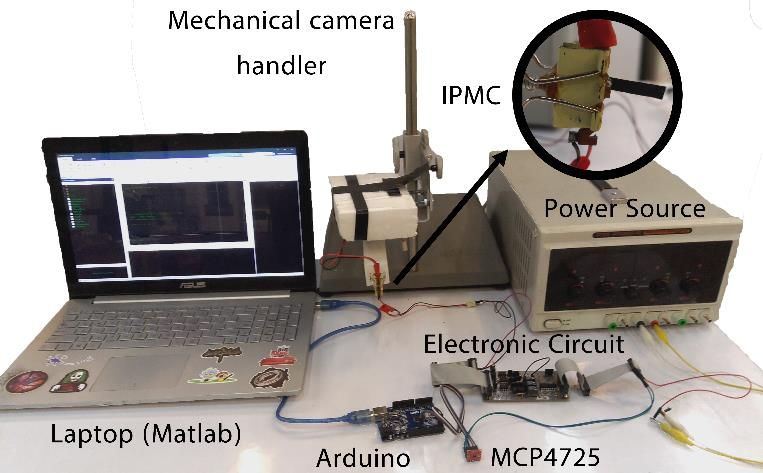
3 current of the disturbance, and G is the surface conductivity of an equation that can describe molecules' velocity inside the IPMC. membrane. By taking the first derivative of Eq. (13) with By replacing ( , ) with Eq. (3) in Eq. (7) and taking respect to t, we reach to Eq. (18). c ( x,t ) − G ( ) derivation with respect to t and x and ignore small terms, just like the previous work, we reach Eq. (11). c ( x, t ) = = ˆ x − ( t ) (18) V p +v2 ke t 2 c ( x, t ) w ( x, t ) c ( x, t ) w ( x, t ) Now we have to talk about 2 . Let us consider that the 1 + ln + ln xt w ( 0, t ) t x w ( 0, t ) amplitude of 2 is approximately the same as the value of . It is needed to make assumptions on the speed of water molecules. c ( x, t ) w ( x, t ) 2 w ( x, t ) (11) + ln + c ( x, t ) ln As seen from Eq. (18), we can define the value of water x t w ( 0, t ) xt w ( 0, t ) molecules' velocity. We can then assure that the value of the speed of perturbation of water molecules in the membrane is eG + c ( x, t ) ( v1 ( t ) + v2 (t ) ) = 0 high enough to satisfy our assumptions. Also, suppose its KTAx frequency is relatively higher than the frequency of the IPMC's As discussed, the hydrated sodium cations reciprocate tip displacement. In that case, we can see that water molecules' between anode and cathode, so we need to specify the value of movement and their perturbation can be considered working 2 . In order to create a uniform distribution of water molecules separately. In this situation, there would be a section at the all over the membrane, we need to apply a specific voltage ( 2 ) middle of IPMC, where water molecules will steer continuously which perturbed the free water molecules in the whole Nafion and make the perturbation that we want. membrane. So, in the steady-state, the free water molecules So, these assumptions about frequency and amplitude would concentration is homogenous in the Nafion: give us a proper disturbance signal, which can be applied to our w ( x ,t ) (12) input to make the desired output. 1 . w ( 0, t ) III. EXPERIMENTAL RESULTS Because 1 ( ) is a step voltage, we can solve Eq. (11) and reach the solution of the concentration, which is provided in Eq. It is needed to evaluate our experimental data with some (13) (Details have been described in Appendix A). primary and advanced criteria to verify the proposed method. x −( t ) First, we introduce our hardware apparatus, and then the c ( x, t ) = k e (13) required criteria and their result on the data were presented. Where A. Hardware apparatus (t ) = G (Vpt + v2 (t )dt ) (14) In Figure 3 the experimental apparatus is shown. It contains several components which are listed: e • Computer with MATLAB 2020a = (15) • Power supply K TAx • Adjustable mechanical camera holder k̂ and are constants based on the given initial and • Camera boundary conditions and is the amplitude of the step voltage • IPMC holder ( 1 ). In order to get the steady-state concentration of hydrated • IPMC sodium cations, we can use Eq. (13). We expect that the • Arduino microcontroller concentration should be constant near the cathode. To satisfy • MCP4725 Digital to Analog this expectation, the value of α should be positive. • Analog circuits lim c ( x, t ) = c (16) The desired signal is generated in MATLAB and sent to our ( x,t )→( h, ) analog circuit via Arduino Uno and MCP4725. The input of the 0 (17) analog circuit change by amplitude and offset to the desired As discussed earlier, Nafion-based IPMCs suffer from the values. When the signal is applied to the IPMC, a video will BR effect, which can be reduced by applying an external capture the IPMC's functioning by the camera. Then, we can voltage ( 2 ) as a disturbance. Applying an external disturbance extract data from these videos by processing techniques [11]. In will not cause any instability to the ionic distribution throughout Figure 4 which is also discussed in [22], the electronic circuit's the membrane. The displacement dynamic of IPMC and the schematic view is shown with its inputs. The place of IPMC in hydrated sodium cations' movement dynamic are not the background would capture by the camera, and the comparable, and the displacement dynamic is significantly coordination of IPMC's tip stored for further processes. slower than the movement dynamic. Despite the hydrated sodium cations' movement, the overall displacement is stationary concerning the IPMC's bending because ions in the membrane move much faster than the IPMC's bending speed. As mentioned before, the dynamic of hydrated cations should be swifter compared to the dynamic of IPMC itself to eliminate the BR effect. To investigate this occurrence, we need to find
4
g = 3 PO.t settle .t rise (19)
Another evaluation of the step response goodness is fuzzy
logic criteria [18]. Fuzzy logic converts all of the expert
knowledge of a problem to mathematical propositions, which
can be used in system modeling and managing uncertainty [24-
27]. In recent works [11, 18], fuzzy logic criteria have been used
to evaluate the IPMC's step response. Any single step response
criteria cannot evaluate the step response quality because none
is sufficient for evaluation, and also, the geometrical average
( ) is not acceptable [11, 18]. The criterion propose here is
the goodness of the step response ( ), which is described as
below:
Figure. 3. data acquisition setup. = ( , , ) (20)
Here, (. ) is a nonlinear fuzzy mapping, realized by a
Mamdani product inference engine [11]. The BR reduction
amount can be explicated using the step response criteria ( ,
, and ). The step response is considered good if all
three criteria are good, and then the BR effect is suppressed, but
they do not affect the fuzzy criterion equally. On the contrary,
the step response is considered not good if PO is mediocre, but
and are in a reasonable range because the overshoot
has more impact on the goodness of the step response ( )
compared to other criteria. The fuzzy assessment used here
described in [11], both itself and its membership functions,
which are used here because that has shown promising results
Figure. 4. Schematic of extracting features from IPMC's response to the
for [11, 18].
applied signal. V1 is the step voltage, and V2 is the disturbance. X and Y
are the tip displacement in the x and y directions. [22] The step response performance criteria of the IPMC's
functioning and the geometric average of the step response
criteria have been presented in Figure. 9 to Figure. 1. Also,
B. Results fuzzy criterion ( ) shown in Figure. 13.
The IPMC used in this experiment is made of Nafion 117,
and its electrodes are Platinum. The size of the IPMC is
23×3.5×0.2 mm3. As discussed in [11], for observing the BR
effect reduction in the IPMC, the step response should show
more stability and contains less slope. To this end, a step
voltage ( 1 = 4 ) is produced and then applied to the IPMC in
addition to a specified signal ( 2 ). We apply the disturbance as
2 and observe the response to the step voltage for values of 2 ,
0.25, 0.5, and 1 time of 1 amplitude, and different frequencies
of disturbance, including 60, 600, 1500, 3000, 4000, 6000 Hz.
As mentioned before, our suggested signal for 2 is a
relatively high-frequency disturbance ("High" compared to the
working frequency of IPMC). This specific disturbance stirs the
water molecules in the membrane during the IPMC bending
process. The step response component along the X-axis has
been shown in Figure 5, respectively, for all inputs. Also, the Figure. 5. Tip displacement of the IPMC in X-direction in response to a
step voltage of which is 4V. S1-6, amplitude is . ∗ . S7-12,
maximum displacement of IPMC's tip and final displacement
amplitude is . ∗ . S13-18, amplitude is . Frequency of each group
of IPMC's tip have been displayed in Figure 7 and Figure 8. is 60, 600, 1500, 3000, 4000, and 6000. S19 is data without disturbance.
The best performance criteria in the evaluation of the time
domain step response are its components. These components
are settling time ( ), rise time ( ), and percentage
overshoot ( ). It is desired that all of these criteria should be
minimized. Therefore, a geometric average of all the step
response criteria is introduced as a single criterion to achieve an
acceptable step response [23].5 in Figure 8. By calculating PD for S14 and S15, it can be demonstrated that both values are 0.11. In this situation, when none of our criteria can decide between S14 and S15, we can concentrate just on the maximum displacement of IPMC. This parameter is crucial for us. First, it is essential because we don't want too much displacement drop because of adding disturbance to step voltage; second, we pursue eliminating the BR effect in large displacement. By comparing the maximum displacement of S14 and S15, S14 has 23 percent more displacement than S15. Also, this value for the final displacement is 23 percent. This result can also be seen in Figure 6. So overall, S14 ( 2 = 1 and frequency is 600 Hz) has the best outcome in the elimination of the BR effect. Figure. 6. Tip displacement of the IPMC in X-direction in response to a step voltage of which is 4V. In S14, = and frequency is 600Hz. In S15, = and frequency is 1500Hz. In S19, there is no and IPMC works conventionally. To begin our comparison for choosing the best noisy input, we must start from the most straightforward criterion that we introduced, and that criterion is step response. It is needed to name the inputs to simplify the next part. Each S is input with the same step voltage of 2 = 4 with various disturbance amplitude and frequency values. The result of x displacement for each input is shown in Figure 5. The best three curves shown in Figure 5 are S13, S14, and S16, which have the least back Figure. 7. Maximum displacement of IPMC. Green data is = and = and its value is 8.7678mm. Blue data is = and = relaxation effect observed by the figure with naked eye. If we and its value is 7.1209mm. Maximum value of this chart belongs look at their step response criteria (Figures 9, 10, and 11), the to green data. values for S14 are much more suitable than S13 and S16. Surprisingly, S15 also has outstanding results in terms of step response criteria. Remember that the rise time value (Figure 10) is high for the inputs mentioned because the amplitude of disturbance voltage will prevent the IPMC from bending fast. The curve of S15 in Figure5 has lower x displacement values than S14 but similar values of step response criteria. Their x displacement is traced in Figure 6 with the input without disturbance, which is S19. As it can be seen, all the criteria discussed earlier cannot evaluate the goodness of the step response alone. It is needed to specify the step response with another criterion that contains all of the step response Figure. 8. Final displacement of IPMC. Green data is = and = components. Here, we use the geometric average of step and its value is 7.8794mm. Blue data is = and = response components [18], which is shown in Figure 12. For and its value is 6.4223mm. Maximum value of this chart belongs to green data. this one, the best value, the minimum value, belongs to both S14 and S15, which is not helpful at all. Hence, the fuzzy logic assessment has been used, which is described earlier. By required assumptions, the value of the fuzzy logic criterion is 90 for both S14 and S15. Fuzzy logic shows us that the goodness of S14 and S15 is more than other inputs, which can be perceived previously. We describe new criteria to evaluate the best result for us by maximum displacement and final displacement of IPMC's tip, which are tip displacement's essential values shown in Figures 7 and 8. First, the percentage of displacement disputes from the maximum value to the final value should be checked. It can be calculated from Eq. (56): Figure. 9. Overshoot of IPMC. Green data is = and = and − its value is 11.2751. Blue data is = and = and its value is = (21) 10.8778. Minimum value of this chart belongs to both green and Blue data. Where "MD" is the maximum displacement of IPMC and "FD" is the final displacement of IPMC. The value of maximum displacements is shown in Figure 7, and the final displacements
6 IV. CONCLUSION A method for eliminating the unwanted back relaxation effect of pattern-free IPMC was presented, and by an analytical and experimental investigation, the validity of the method was proved. We experimentally and theoretically proved that, like the patterned IPMCs, by applying a relatively high-frequency disturbance to the pattern-free IPMCs, the hydrated sodium cations will reciprocate rapidly between cathode and anode electrodes result in a perturbation of the free water molecules in the IPMC membrane. This fast reciprocation holds free Figure. 10. Rise time of IPMC. Green data is = and = hydrated cations at the cathode side and helps to reduce the BR and its value is 6.5710s. Blue data is = and = and its effect tremendously in Nafion-based IPMCs. The results value is 6.0745s. Minimum value of this chart belongs to neither blue data showed that the proposed BR elimination approach could or green data and its value is 1.2098s. significantly reduce the BR effect of IPMC, needless to have any pattern on the electrodes of the IPMCs, and unlike the patterned IPMCs, no attenuation will happen in the tip displacement of IPMC, and even we saw the increased tip displacement. V. APPENDIXES A. An analytical solution for reaching Eq. (13): For reaching Eq. (13) using Eq. (11), we need to use the physical knowledge we have from IPMC. A fast-reciprocating movement of hydrated sodium cation will be created in the Figure. 11. Settling time of IPMC. Green data is = and = and its value is 51.1113s. Blue data is = and = and its membrane by applying a disturbance with the primary signal. value is 53.1050s. Minimum value of this chart belongs to green data. In this situation, the concentration of water molecules is almost uniform in the membrane because they are stirred rapidly by the disturbance. Consequently, the free water molecules concentration is almost identical in the steady-state in the membrane of IPMC. As a result, it can be inferred that the free water molecules concentration is uniform throughout the membrane (w(x,t)) including the area around the Anode (w(0,t)), which can be describe as: w( x, t ) 1 (a1) w(0, t ) And respectively: w( x, t ) )0 Figure. 12. Geometric average of step response criterion of IPMC. Green data is = and = and its value is 15.4868. Blue data is = ln( (a2) and = and its value is 15.1960. Minimum value of this chart w(0, t ) belongs to both green and blue data. w( x, t ) ln( )0 (a3) t w(0, t ) w( x, t ) ln( )0 (a4) x w(0, t ) By utilizing equations (a1) to (a4) into Eq. (11) we can obtain following equation: 2c( x, t ) eG + ( v1 ( t ) + v2 ( t ) ) c( x, t ) = 0 (a5) xt KTAx Figure. 13. Fuzzy criterion of IPMC. Green data is = and = Finally by using the separation of variables method, and its value is 90.1. Blue data is = and = and equation (a5) can be solved into Eq. (13). its value is 90.5. Maximum value of this chart belongs to both green and blue data. REFERENCES [1] P.Brunetto, L.Fortuna, P.Giannone, S.Graziani, F.Pagano, "A resonant vibrating tactile probe for biomedical applications based on
7

 IPMC," IEEE Transactions on Instrumentation and Measurement, [17] M. J. Fleming, K. J. Kim, and K. K. Leang, "Mitigating IPMC back
 vol. 59, No. 5, pp. 1453-1462, 2010. relaxation through feedforward and feedback control of patterned
[2] G.H.Feng, and J.W.Tsai, "Micromachined optical fiber enclosed 4- electrodes," Smart Materials And Structures, vol. 21, 2012, doi:
 electrode IPMC actuator with multidirectional control ability for 10.1088/0964-1726/21/8/085002.
 biomedical application," Biomed Microdevices, pp. 169-177, 2011. [18] M. Annabestani, N. Naghavi, and M. Maymandi-Nejad, "From
[3] Y.-c. Chang and W.-j. Kim, "Aquatic Ionic-Polymer-Metal- modeling to implementation of a method for restraining back
 Composite Insectile Robot With Multi-DOF Legs," IEEE/ASME relaxation in ionic polymer–metal composite soft actuators,"
 Transactions On Mechatronics, vol. 18, no. 2, pp. 547-555, 2013. Journal of Intelligent Material Systems and Structures, vol. 29, p.
[4] S. Ruiz, B. Mead, V. Palmre, K. J. Kim, and W. Yim, "A cylindrical 1045389X1878308, 07/24 2018, doi: 10.1177/1045389X18783082.
 ionic polymer-metal compositebased robotic catheter platform: [19] C.Bonomo, P.Brunetto, F.Fortuna, P.Giannone, S.Graziani and
 modeling, design and control," Smart Materials and Structures, vol. S.Strazzeri, , "A tactile sensor for biomedical applications based on
 24, 2015. IPMCs," IEEE Sensors Journal, vol. 8, No. 8, pp. 1486-1493, 2008.
[5] S. Ford, G. Macias, and R. Lumia, "Single active finger IPMC [20] M.Shahinpoor, P.Shahinpoor and D.Soltanpour, "Surgical
 microgripper," Smart Materials and Structures, vol. 24, 2015. Correction Of Human Eye Refractive Errors By Active Composite
[6] R.K. Jain, S.Majumder and A.Dutta, "Micro assembly by an IPMC Artificial Muscle Implants," United States Patent/ US 6511508 B1,
 based flexible 4-bar mechanism," Smart Materials and Structures, 2003.
 vol. 21, No. 7, 2012. [21] Y.Bahramzadeh, and M.Shahinpoor, "Ionic polymer-metal
[7] J. J. Hubbard, M. Fleming, K. K. Leang, V. Palmre, D. Pugal, and composites (IPMCs) as dexterous manipulators and tactile sensors
 K. J. Kim, "Characterization Of Sectored-Electrode Ipmc-Based for minimally invasive robotic surgery," in Proceeding of SPIE 19th
 Propulsors For Underwater Locomotion," in ASME 2011 Annual International Symposium on Smart Structures and
 Conference on Smart Materials, Adaptive Structures and Intelligent Materials, San Diego, California, 11-15 March, 2012.
 Systems, Scottsdale, Arizona, USA, 2011. [22] M. Annabestani, M. H. Sayad, P. Esmaeili-Dokht, R. Gorji, and M.
[8] M. Annabestani, P. Esmaeili-Dokht, S. K. Nejad, and M. Fardmanesh, "Eliminating Back Relaxation in Large-Deformable
 Fardmanesh, "NAFAS: Non-rigid Air Flow Active Sensor, a cost- IPMC Artificial Muscles: A Noise-Assistive Pattern-Free Electrode
 effective, wearable, and ubiquitous respiratory bio-sensor," IEEE Approach," in 2020 27th National and 5th International Iranian
 Sensors Journal, 2021. Conference on Biomedical Engineering (ICBME), 26-27 Nov. 2020
[9] S.Tadokoro , S.Yamagami and T.Takamori, "An actuator model of 2020, pp. 55-60, doi: 10.1109/ICBME51989.2020.9319432.
 ICPF for robotic applications on the basis of physico-chemical [23] F.Carpi , and D.De Rossi, "Electroactive Polymer-Based Devices
 hypotheses," Proceeding of IEEE International Conference on for e-Textiles in Biomedicine," IEEE Transactions On Information
 Robotics and Automation-San Francisco-USA, pp. 1340–1346, Technology In Biomedicine, vol. 9,no 3, 2005.
 2000. [24] M. Annabestani, A. Rowhanimanesh, A. Mizani, and A. Rezaei,
[10] Y.Gong, J.Fan, C.Y. Tang, and C.P.Tsui, "Numerical Simulation of "Fuzzy descriptive evaluation system: real, complete and fair
 Dynamic Electro-Mechanical Response of Ionic Polymer-Metal evaluation of students," Soft Computing, vol. 24, no. 4, pp. 3025-
 Composites," Journal of Bionic Engineering, pp. 263–272, 2011. 3035, 2020/02/01 2020, doi: 10.1007/s00500-019-04078-0.
[11] M. Annabestani, M. Maymandi-Nejad, and N. Naghavi, [25] M. Annabestani and M. Saadatmand-Tarzjan, "A New Threshold
 "Restraining IPMC Back Relaxation in Large Bending Selection Method Based on Fuzzy Expert Systems for Separating
 Displacements: Applying Non-Feedback Local Gaussian Text from the Background of Document Images," Iranian Journal
 Disturbance by Patterned Electrodes," IEEE Transactions on of Science and Technology, Transactions of Electrical Engineering,
 Electron Devices, vol. 63, no. 4, pp. 1689-1695, 2016, doi: vol. 43, no. 1, pp. 219-231, 2019/07/01 2019, doi: 10.1007/s40998-
 10.1109/TED.2016.2530144. 018-0160-7.
[12] S.Nemat-Nasser, "Micromechanics of actuation of ionic polymer- [26] F. Hasanzadeh and F. Faradji, "An ICA Algorithm Based on a
 metal composites," Journal of Applied physics, vol. 92, No. 5, pp. Fuzzy Non-Gaussianity Measure," in 1st International Conference
 2899-2915, 2002. on New Research Achievements in Electrical and Computer
[13] S.-M. Kim and K. J. Kim, "Palladium buffer-layered high Engineering, 2016.
 performance ionic polymer–metal composites," Smart Materials [27] F. Hasanzadeh, M. Annabestani, and S. Moghimi, "Continuous
 And Structures, vol. 17, 2008. emotion recognition during music listening using EEG signals: A
[14] S. Nemat-Nasser and S. Zamani, "Effect of solvents on the chemical fuzzy parallel cascades model," Applied Soft Computing, vol. 101,
 and physical properties of ionic polymer-metal composites," p. 107028, 2021/03/01/ 2021, doi:
 Journal Of Applied Physics vol. 99, 2006. https://doi.org/10.1016/j.asoc.2020.107028.
[15] D. B. Nikhil and K. Won-jong, "Precision Position Control of Ionic vol. 65, no. 12, pp. 2866-2872, 2016.
 Polymer Metal Composite," in American Control Conference
 Boston, Massachusetts, 2004, pp. 740-745.
[16] K. Takagia, S. Hirayama, S. Sano, N. Uchiyama, and K. Asaka,
 "Reduction of the stress-relaxation of IPMC actuators by a
 fluctuating input and with a cooperative control," in Electroactive
 Polymer Actuators and Devices (EAPAD), Y. Bar-Cohen, Ed., 2012,
 doi: 10.1117/12.915161.
You can also read