LTC 8x00/90 Integrated Series Allegiant Matrix/Control Systems
←
→
Page content transcription
If your browser does not render page correctly, please read the page content below
CCTV | LTC 8x00/90 Integrated Series Allegiant Matrix/Control Systems

LTC 8x00/90 Integrated Series Allegiant
Matrix/Control Systems
                                                              ▶ Models from 8 cameras by 2 monitors to 32 cameras by
                                                                6 monitors
                                                              ▶ Compact single bay construction
                                                              ▶ Integral alarm interface and signal distribution
                                                              ▶ Powerful alarm handling features
                                                              ▶ SalvoSwitching® and SatelliteSwitch® capability
                                                              ▶ PC-based software package available

The LTC 8100 Series, LTC 8200 Series, and LTC 8300 Series     Utilizing the unit’s integral signal distribution ports,
Allegiant® video switcher/control systems combine both        connections to on-site receiver/drivers are easily made. On-
switching and computer technology to provide powerful         site receiver/drivers provide operator control of pan, tilt,
performance and unique system features for the security       zoom; multiple pre-positions; four auxiliaries; auto-pan, and
user. Offering full matrix switching capability, these        random scan. These systems also support variable speed
systems can be programmed to display the video from any       operation and full programming functions of AutoDome®
camera on any monitor, either manually or via independent     Series dome cameras.
automatic switching sequences.                                When combined with an LTC 8016 Allegiant Bilinx™ Data
These systems provide from 8 camera inputs, 2 monitor         Interface unit, these switcher/controllers support
outputs to 32 camera inputs, 6 monitor outputs, 2 to 4        operations using Bilinx communication. With Bilinx, PTZ
keyboards, 8 to 32 direct connect alarm input points, an      control is accomplished using a bidirectional
integral signal distribution unit, and a computer interface   communication protocol embedded in the video signal of
port. A logging printer port is available in the LTC 8300     Bosch Dinion™ and AutoDome® CCTV cameras. In addition,
Series systems.                                               Bilinx uses the standard video cable to transmit alarm and
These systems can be programmed with up to 60                 status messages from the cameras, providing superior
sequences which can be run independently of each other in     performance without the need for separate data
either a forward or reverse direction.                        transmission cables.
Any of the sequences can utilize the SalvoSwitching           With their built-in alarm interface capability, an external
capability where any number of system monitors may be         contact closure or logic level can be used to automatically
selected to switch as a group. Using the optional             activate any camera to be displayed. Any monitor or group
LTC 8059/00 Master Control Software package or the            of monitors can be set to display cameras under alarm
LTC 8850/00 Graphical User Interface software package,        conditions. The base system contains three built in alarm
sequences can be made to activate and deactivate              response modes: basic, auto-build, and sequence & display.
automatically based upon the time of day and the day of       In addition to these three modes, the PC-based software
week.                                                         packages offer the ability to combine any or all of the three
                                                              standard modes within the same system. Alarm video may

                                                                                               www.boschsecurity.com
2 | LTC 8x00/90 Integrated Series Allegiant Matrix/Control Systems
be selected to reset either manually or automatically. In These systems can serve as the master switcher in a
addition, a 16‑character alarm title can be selected to SatelliteSwitch® configuration. This innovative
appear instead of the camera title during alarm conditions. SatelliteSwitch feature enables a single system to
System operation and programming is accomplished using communicate with remotely located "Satellite" systems.
a full-function, ergonomically designed keyboard (sold Any Allegiant model can serve as a master or remote
separately). Built-in operator priority levels and the ability Satellite switcher. This powerful feature permits the design
to restrict certain operators from controlling designated of a distributed matrix video switching system with control
functions provide maximum flexibility. at one central location and individual control at the local
sites. The main control site can view/control local cameras
These systems include a black outlined 48-character on-
plus cameras located at any of the remotely distributed
screen display for time-date, camera number, camera ID
Satellite sites. The Satellite sites can view/control only
(16-characters), an icon to identify controllable cameras,
cameras associated with their own site. When used in this
and monitor (12-characters) or status information. Over
type of configuration, the main system can access up to 256
235 characters are available when programming camera ID
cameras located anywhere in the system.
and monitor titles.
Windows is a registered trademark of Microsoft Corp.
Utilizing a Windows®-based PC and the optional
LTC 8059/00 Master Control Software package or
LTC 8850/00 GUI software, enhanced programming and
switching features can be obtained. A user-friendly Certifications and Approvals
spreadsheet format provides the ability to enter camera and
Electromagnetic Com- Complies with FCC Part 15, ICES-003, and CE
monitor titles, program of operator names and priorities, 64
patibility (EMC) regulations
timed event actions, change system parameters, program
Product Safety Complies with CE regulations, UL, CSA, EN, and
camera sequences, install lockouts, and access the
IEC Standards
advanced alarm handling screens with speed and efficiency.
The programmed information may then be transferred into
the Allegiant system, stored on disk, or printed out directly
from a printer connected to the PC.
Installation/Configuration Notes
The LTC 8850/00 Bosch GUI software is designed around
an intuitive graphic-based interface. The GUI provides high
performance programming, control and monitoring of all
system functions by using on-screen icons to reflect real
time status of the devices controlled by the system. The
LTC 8850/00 GUI software also provides the ability to
monitor system status events. System alarms, switching
functions, sequence events, keyboard actions, and video
loss information can be viewed in real time on the PC screen
and, if desired, logged to the PC hard drive.
The software also provides the ability to enable an on-
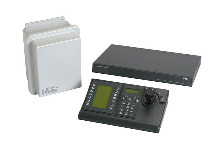
LTC 8300 Series
screen indicator for easy identification of controllable Main CPU Bay
cameras.
The LTC 8300 Series contain a logging printer output port
which accepts a standard RS 232 serial printer. This
provides a permanent record of system status showing time
and date for changes such as: incoming alarms, 1 2 3 4 5 6
acknowledgment of alarms, sequence loading, user log-on BOSCH BOSCH
to keyboard, transfer of system tables and sequences, video
Prod Mon Prod Mon
Clr Shot Clr Shot
1 2 3 1 2 3
4 5 6 4 5 6
7 8 9 7 8 9
0 0
loss messages, and a power up reset message. In addition,
the printer can be used to obtain a hard copy of the system's
configuration tables and sequences. Typical LTC 8300 Series Configuration Diagram
These systems provide powerful macro capabilities. The
macros can be activated using Allegiant Series keyboards,
system time event functions, alarm activations, and via
special function icons in the LTC 8850/00 GUI software.LTC 8x00/90 Integrated Series Allegiant Matrix/Control Systems | 3
1 Additional System Cameras 8 Receiver/Driver
2 Up to 32 Video Inputs Maximum 9 Up to 32 Receiver/Driver Units
3 3 m (10 ft) Interconnect Cable Supplied with Keyboard 10 Up to 1.5 km (5000 ft) Using 18 AWG Shielded Twisted Pair Cable
4 Video Coax (Belden 8786 or Equivalent)
5 Up to six (6) Monitor Outputs 11 Optional LTC 8059/00 MCS or LTC 8850/00 GUI Software Package
can be Run on a Windows® based PC
6 Maximum of four (4) Allegiant Series Full Function Keyboards up to
1.5 km (5000 ft) Away Using Optional Remote Hookup Kit 12 Additional System Cameras
7 LTC 8300 Series Main CPU Bay 13 3 m (10 ft) RS-232 Interface Cable provided with Optional Software
Package
14 LTC 8300 Series Main CPU Bay
15 Serial RS-232 Logging Printer Capability
16 3 m (10 ft) Interconnect Cable Supplied with Keyboard
17 Up to six (6) Monitor Outputs
18 Maximum of 4 Allegiant Series Full-Function Keyboards up to 1.5 km
(5000 ft) Using Optional Remote Hookup Kit
BOS CH BOS CH
BOS CH
BOS CH
Prod Mon
Clr Shot
1 2 3
4 5 6
7 8 9
0
BOS CH BOS CH
Prod Mon Prod Mon
Clr Shot Clr Shot
1 2 3 1 2 3
4 5 6 4 5 6
7 8 9 7 8 9
0 0
BOS CH BOS CH
BOS CH
BOS CH
Prod Mon
Clr Shot
1 2 3
4 5 6
7 8 9
0
LTC 8300 Series Full Capacity Configuration Diagram
(32 Cameras by 6 Monitors)
1 Typical AutoDome Camera
2 Video Coax
3 Twisted-Pair Typical
4 32 Separate Alarm Inputs
5 Contact Closure or Active Low Logic Level Typical Main Allegiant Control Center
6 Six (6) Pairs of Relay Outputs
7 Pan and Tilt
www.boschsecurity.com4 | LTC 8x00/90 Integrated Series Allegiant Matrix/Control Systems
1 Typical System Monitors Field Time Waveform Distortion1 2% maximum
(Local and/or Remote Video)
Line Time Waveform Distortion1 1% maximum
2 Video
Short Time Waveform Distortion1 2% maximum
3 Typical Fixed Cameras
4 Typical Alarm Input Contact to Activate Local or Satellite Cameras Video Bandwidth (-3 dB) 2 22 MHz
5 Typical Controllable Camera Frequency Response 2 ± 1.0 dB to 10.5 MHz
6 Typical LTC 8100, LTC 8200, or LTC 8300 Allegiant System Signal-to-Noise1 60 dB at 3.58 MHz unweighted mini-
7 Bi-Phase Data Lines to All Local PTZ Camera Sites mum
(Typical at 3.58 MHz)
8 Typical IntuiKey Keyboard
Crosstalk (Adjacent Channel) -52 dB at 3.58 MHz
9 Bi-Phase Control and Satellite Switching Data
Differential Gain1 2% maximum
10 One (1) Bi-Phase Data Line to Each Remote Satellite Site
Differential Phase1 1.3° maximum
11 Incoming Video TRUNK Lines From All Satellite Sites
12 Typical Allegiant Satellite Site Chrominance Luminance Gain1 96% to 104%
13 Typical Local Monitors (Local Video Only) Chrominance Nonlinear Phase1 2° maximum
14 Typical Fixed Cameras Luminance Nonlinearity1 4% maximum
15 Typical Alarm Input Contact (For Local Alarms Only) Switching Crosspoint matrix
16 Bi-Phase Data DC Output 0V
17 IntuiKey Keyboard (PTZ Control of Local Cameras Only) 1 Meets EIA/TIA - 250C Medium Haul Standard.
18 LTC 8780 Data Converter 2 One camera to one monitor.
19 LTC 8569 Code Merger
Environmental
20 Bi-Phase Control + Satellite Data
Operating Temperature 4°C to 55°C (40°F to 131°F)
Storage Temperature –40°C to 60°C (–40°F to 140°F)
Technical Specifications Altitude 4500 m (15,000 ft)
System Humidity 0% to 95% relative, non-condensing
LTC 8100, LTC 8200, LTC 8300 Series Bay
Capacities
Electrical
Model No. LTC 8100 LTC 8200 LTC 8300
Video Inputs (Standard) 8 16 32 Model No. Voltage Range Nominal Power2
Video Inputs (Looping) 8 16 32 LTC 8100/90 108 to 253 VAC, 50/60 Hz 15 W
Video Inputs (Satellite) 256 256 256 LTC 8200/90 108 to 253 VAC, 50/60 Hz 17 W
Video Outputs 2 5 6 LTC 8300/90 108 to 253 VAC, 50/60 Hz 18 W
Alarm Inputs 8 16 32 2 Power at rated voltage fully loaded.
Alarm Outputs 2 5 6 Connectors
Bi-Phase Outputs 8 12 16 Video Inputs and Monitor Outputs BNC
Keyboards 2 4 4 Looping Video Connections
RS-232 Ports (Console) 1 1 1 LTC 8100 Series 8 BNC
RS-232 Ports (Printer) 0 0 1 LTC 8200 Series One 34-pin ribbon connector used
Receiver/Drivers 8 16 32 with the LTC 8808/00 video inter-
(Standard) connect panel (not included)
Receiver/Drivers (Satellite) 256 256 256 LTC 8300 Series Two 34-pin ribbon connectors used
with the LTC 8808/00 video inter-
Electrical connect panel (not included)
Input Voltage Level 0.5 Vp-p to 2 Vp-p
(Composite Negative Sync)
Gain Unity ± 2% (75 Ohm terminated)
Pulse/Bar Ratio1 94% to 106%
2T Pulse K Factor1 2.5% maximum
Bar Amplitude1 96% to 106%LTC 8x00/90 Integrated Series Allegiant Matrix/Control Systems | 5
External Accessory Interfaces Ordering Information
CONSOLE RS-232 port for external PC or control interface LTC 8100/90 Allegiant Matrix Switcher LTC 8100/90
(default = 19,200 baud) 9-pin D-type connector 8 camera inputs/2 monitor outputs, incl. Bi-
ALARMS Inputs use removable screw terminal connectors. phase outputs and alarm contacts, 108 to
Relay outputs provide alarm output connections. 253 VAC, 50/60 Hz
(Contact rating = 1.5 A at 30 VDC) LTC 8200/90 Allegiant Matrix Switcher LTC 8200/90
PRINTER RS-232 port for system logging printer 16 camera inputs/5 monitor outputs, incl. Bi-
(LTC 8300 Series only) (Default = 19,200 baud) 9-pin D-type connector phase outputs and alarm contacts, 108 to
253 VAC, 50/60 Hz
BIPHASE OUT Multiple ports provide receiver/driver connec-
tions when used in a daisy chain configuration. LTC 8300/90 Allegiant Matrix Switcher LTC 8300/90
Removable screw terminal connector blocks. 32 camera inputs/6 monitor outputs, incl. Bi-
phase outputs and alarm contacts,108 to
KEYBOARDS 6-pin RS-485 ports for Allegiant keyboard use 253 VAC, 50/60 Hz
Mechanical Software Options
Construction Steel chassis with sheet metal cover and SFT-VASA Hybrid IP - Analog/Matrix Video SFT-VASA
plastic bezel over IP Integration Software
Finish Charcoal LTC 8850/00 GUI Allegiant Single User LTC 8850/00
Dimensions Software Package
LTC 8100, LTC 8200 Series 440 x 305 x 40 mm LTC 8059/00 Allegiant Master Control LTC 8059/00
(H x D x H) (17.3 x 12 x 1.7 in.) Software
LTC 8300 Series 440 x 305 x 89 mm
(H x D x H) (17.3 x 12 x 3.5 in.)
Weight
• LTC 8100, LTC 8200 Ser- 4 kg (8.8 lb)
ies
• LTC 8300 Series 4.8 kg (10.7 lb)
Rack Mount (Integral) Brackets for mounting one unit in a
48 cm (19 in.) EIA rack
• LTC 8100, LTC 8200 Ser- One (1) standard rack unit high
ies
• LTC 8300 Series Two (2) standard rack units high
Accessories
The Allegiant accessory products provide many optional features to the base
Allegiant switching systems. Accessory products include keyboards, key-
board extension kits, Allegiant Bilinx Data Interface unit, receiver/driver
units, switcher/followers, and code merger units. All accessory products
are designed to be installer-friendly and compatible throughout the Allegiant
series systems. See the Allegiant Accessories datasheet.
www.boschsecurity.com6 | LTC 8x00/90 Integrated Series Allegiant Matrix/Control Systems Americas: Europe, Middle East, Africa: Asia-Pacific: Represented by Bosch Security Systems, Inc. Bosch Security Systems B.V. Bosch Security Systems Pte Ltd 130 Perinton Parkway P.O. Box 80002 38C Jalan Pemimpin Fairport, New York, 14450, USA 5600 JB Eindhoven, The Netherlands Singapore 577180 Phone: +1 800 289 0096 Phone: + 31 40 2577 284 Phone: +65 6319 3450 Fax: +1 585 223 9180 Fax: +31 40 2577 330 Fax: +65 6319 3499 security.sales@us.bosch.com emea.securitysystems@bosch.com apr.securitysystems@bosch.com www.boschsecurity.us www.boschsecurity.com www.boschsecurity.com © Bosch Security Systems Inc. 2008 | Data subject to change without notice T2525408523 | Cur: en-US, V10, 9 Jul 2008
You can also read