LV ENGINE Project Progress Report Work carried out during 2020 - Internal Use - SP Energy Networks
←
→
Page content transcription
If your browser does not render page correctly, please read the page content below
LV ENGINE
  Project Progress Report
Work carried out during 2020

       Internal Use
LV Engine Project Progress Report - 2020

                                             About Report

Report Title                 :       LV Engine Project Progress Report 2020

Report Status                :       Final – 17th January 2021

Project Reference            :       LV Engine

Date                         :       DD/MM/YYYY

                                            Report Progress

Created by                   :       Ali Kazerooni

Reviewed by                  :       Michael Eves, Robbie Macquarrie, Ranit Edgar

Approved by                  :       James Yu

                                                                                                                2
         Level of confidentiality:                               Take care of the environment.
                                                                 Printed in black and white and only if necessary.

                                              Internal Use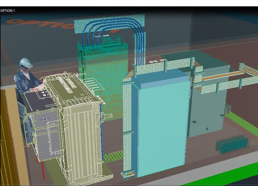
LV Engine Project Progress Report - 2020

Contents
1 Executive Summary ...................................................................................................................... 5
   1.1        Background ....................................................................................................................... 5
   1.2        LV Engine overview .......................................................................................................... 5
   LV Engine power electronics products ......................................................................................... 6
   1.3        Project Highlights .............................................................................................................. 6
   1.4        Project Issues ................................................................................................................... 7
   1.5        Key lessons learnt ............................................................................................................ 8
   1.6        Summary of key activity in next reporting period ............................................................. 9
2 Project Manager’s Report ........................................................................................................... 10
   2.1        Project Progress ............................................................................................................. 10
      2.1.1      Work Package 2 – Partner Selection .......................................................................... 12
      2.1.2      Work Package 3 – Design and Manufacturing of SST ............................................... 13
      SST Topology 1 ...................................................................................................................... 15
      SST Topology 2 ...................................................................................................................... 18
      2.1.3      Work Package 4 – Network Integration Testing ......................................................... 21
      2.1.4      Work Package 5 – Live Trial ....................................................................................... 21
      2.1.5      Work Package 6 –Development of Novel Approach for Transformer Selection ........ 34
      2.1.6      Work Package 7 – Dissemination and knowledge sharing ........................................ 36
   2.2        Lessons learnt................................................................................................................. 37
      2.2.1      Work Package 2 .......................................................................................................... 37
      2.2.2      Work Package 3 .......................................................................................................... 37
      2.2.3      Work Package 5 .......................................................................................................... 40
      2.2.4      Work Package 6 .......................................................................................................... 41
      2.2.5      Work Package 7 .......................................................................................................... 41
   2.3        Project reports and materials.......................................................................................... 43
   2.4        Project Issues ................................................................................................................. 44
   2.5        Outlook to the next reporting period ............................................................................... 45
3 Business Case Update ............................................................................................................... 47
4 Progress against plan ................................................................................................................. 48
   4.1        Key Achievements and project highlights....................................................................... 48
      4.1.1      SST Design ................................................................................................................. 48
      4.1.2      Trial Site Developments .............................................................................................. 48
   4.2        Project issues.................................................................................................................. 48
   4.3        Key activities planned for upcoming reporting period (2021/22) .................................... 48
   4.4        Dissemination ................................................................................................................. 48
5 Progress against budget [CONFIDENTIAL] ............................................................................... 50
                                                                                                                                                3
               Level of confidentiality:                                                  Take care of the environment.
                                                                                          Printed in black and white and only if necessary.

                                                               Internal Use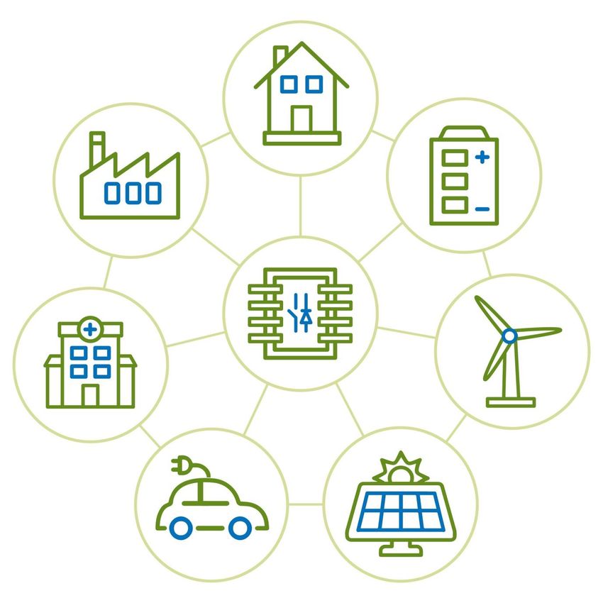
LV Engine Project Progress Report - 2020

6 Project Bank Account [Confidential] ........................................................................................... 51
7 Project Deliverables .................................................................................................................... 52
8 Data access details ..................................................................................................................... 53
9 IPR .............................................................................................................................................. 54
10 Risk Management [CONFIDENTIAL] ....................................................................................... 55
11 Accuracy Assurance Statement................................................................................................ 56
12 Material Change Information .................................................................................................... 57
13 Other ......................................................................................................................................... 58

                                                                                                                                                     4
                Level of confidentiality:                                                    Take care of the environment.
                                                                                             Printed in black and white and only if necessary.

                                                                 Internal Use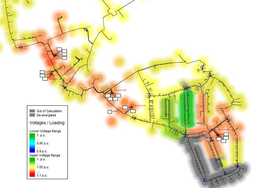
LV Engine Project Progress Report - 2020

1 Executive Summary

1.1 Background
SP Energy Networks, in collaboration with UKPN, submitted the proposal for LV Engine under the
Network Innovation Competition (NIC) mechanism in 2017. WSP, University of Strathclyde, and
University of Kiel have also provided technical support for the proposal preparation. Ofgem
approved the proposal and issued the Project Direction on the 16th of January 2018.The project
commenced in January 2018 and is due to conclude in December 2022.

The LV Engine innovation project intends to trial Smart Transformers (ST) within secondary
substations as the central point of an active and intelligent 11kV and LV distribution network. The
ST trialled during the project will bring together sophisticated power electronic hardware with
intelligent network monitoring and control to maximise the performance and efficiency of the
distribution network.
This is the third in the series of annual progress reports for the LV ENGINE project, covering the
project reporting period January 2020 to January 2021, the “reporting period”.

1.2 LV Engine overview
A ST consists of a Solid-State Transformer (SST) and a Smart Control System (SCS). SST uses
power electronic technologies to deliver several functionalities, SCS, however, provides the control
set points to SST based on data gathered and analysed from different monitored points in the
network. LV Engine aims to demonstrate the following Core Functionalities can be delivered by
deploying SST at secondary substations:
   •   Voltage regulation at LV Networks;
   •   Capacity sharing with other substations;
   •   Cancelation of LV imbalance load seen by the HV network;
   •   Reactive power compensation and power factor correction at secondary substations;
   •   Provision of LV DC to supply rapid and ultra-rapid EV chargers.

                                       Figure 1 LV Engine project concept

                                                                                                                   5
           Level of confidentiality:                                Take care of the environment.
                                                                    Printed in black and white and only if necessary.

                                                 Internal Use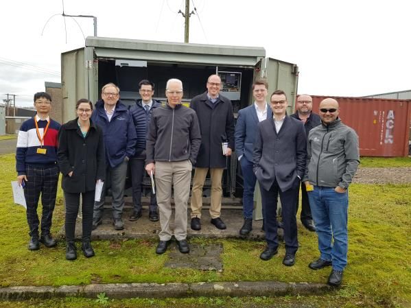
LV Engine Project Progress Report - 2020

LV Engine power electronics products
As the focus of the LV Engine project is to demonstrate the performance of the Core Functionalities
required by the network, different SST innovative topologies may provide these Core
Functionalities in an efficient and reliable manner at secondary substation. There are different
possible SST topologies which have been considered as products of LV Engine:
    •   Topology 1 - Topology using a conventional low frequency 50Hz (LF) transformer –This
        topology uses power electronics devices at the secondary side of conventional LF
        transformers (11kV/0.4kV). The power electronic devices can be added to the existing
        distribution transformers to deliver the Core Functionalities of LV Engine. The aim is to
        enhance Technology Readiness Level (TRL) of this product from 6 to 9.

                                                                Power
                                 11kV                         Electronic          0.4kV
                                                                device

                                                                                  +/- 475 VDC

                                          Figure 2 SST Topology 1

    •   Topology 2 - Topology using a High Frequency (HF) transformers – Using HF
        Transformers and power electronics may allow a modular and compact design while
        delivering the LV Engine Core Functionalities. SPEN recognises that this topology may
        require a larger effort for design and manufacturing compared to the approach of retrofitting
        an LF transformer with power electronics. The aim is to enhance TRL of this product from
        5 to 8.

                                   11kV    Power Electronic       0.4kV
                                               device

                                                                    +/- 475 VDC

                                          Figure 3 SST Topology 2

1.3 Project Highlights
The project highlights in this reporting period are as follows:
    •   SST Design – Following a competitive tender conducted in 2019, ERMCO-Gridbridge
        (EGB) was appointed as LV Engine SST manufacturing partner in November 2019. After
        staff mobilisation, EGB commenced the design process for both SST Topologies in early
        Q1 2020. The design process was initiated through the Project Inception phase, where
        regular detailed discussions with the SPEN team were held to translate each of the
        technical/functional requirements specified within the Smart Transformer Technical
        Specifications1 (LV Engine’s Deliverable #1) to an element of the electrical, control and
        mechanical design.

1

https://www.spenergynetworks.co.uk/userfiles/file/LV_Engine_Deliverable1_Smart_Transformer_Technical_Spec
ification_REDACTED.pdf

                                                                                                                    6
           Level of confidentiality:                                 Take care of the environment.
                                                                     Printed in black and white and only if necessary.

                                               Internal Use
LV Engine Project Progress Report - 2020

           o    SST Topology 1 – Detailed electrical and mechanical designed have been
                developed and agreed with SPEN. Different components of the design have been
                ordered. The majority of key components will be delivered in Q4 2020. The
                benchtop testing and prototyping will be the main activity in Q1 2021.
           o    SST Topology 2 – Detailed electrical deign and optioneering for different topologies
                were carried out. Extensive engagements with academic and semiconductor
                suppliers provided promising solutions to some of the challenges identified for
                development.
       The SST detailed design report has been submitted to Ofgem as part of LV Engine
       Deliverable #2.
   •   Control System Project Partner – The Intelligent Control System project partner has
       been appointed. In order to ensure the best value to customer for future roll outs of
       controllable devices (such as LV Engine), a collaboration arrangement between Angle-DC
       and LV Engine have been set up to develop a holistic control system for distribution
       networks. The intention is to integrate the functionalities required in the two projects,
       identify the overlaps especially in control algorithms and develop a holistic central control
       system.

   •   Trial sites for LVAC schemes ready for commissioning – Progress made as planned
       on detailed design work for Wrexham trial sites where the aim is to demonstrate the AC
       functionalities of LV Engine. Several desktop studies demonstrating performance of the LV
       Engine schemes and the protection strategy were carried out to inform the design.
       Electrical design and layouts of the substation are now also completed.

   •   Trial sites for LVDC schemes ready for commissioning – The project has
       commissioned the design of civil and structural design work associated with the substation.
       Following the sign off the connection agreement, the physical plant details was finalised.
       The majority of electrical design have been concluded. The wayleaves for HV cable
       installation have been granted and acquiring legal rights required to maintain and operate
       the plant is in progress.

   •   LV Automation – The project has decided to appoint an LV automation supplier through
       a tender process, developing a fit for purpose scope for LV automation equipment and
       services, including engineering services required by the vendor. The tender documents
       were submitted in Q4 2020, with the evaluation process ongoing.

   •   Project Dissemination – The learnings of the project and its objectives have continued
       to be widely disseminated through ENIC, international conferences, peer-reviewed
       journals and a webinar in collaboration with Power Electronics UK and CSA Catapult.

1.4 Project Issues
We have encountered the following project issues in this reporting period, nonetheless there is no
Material Change to be reported at this stage:

   •   Covid-19 Pandemic – The risk of pandemic and its impact worldwide was not expected
       during LV Engine programme development. The recent pandemic has introduced a
       number of issues to the project, nonetheless, we have been working to find alternative
       solutions and reduce the impacts where possible. The issues and the solutions are as
       follows:

           o    Supply chain – The lead times for procuring some of the components have been
                longer than initially expected. In some cases, the suppliers temporarily suspended

                                                                                                             7
          Level of confidentiality:                           Take care of the environment.
                                                              Printed in black and white and only if necessary.

                                           Internal Use
LV Engine Project Progress Report - 2020

                   all or part of the orders due to shortage of raw materials. That especially became
                   an issue for the components required for manufacturing SSTs. EGB have reported
                   several of the issues, however, they actively sought to change to suppliers with
                   larger stock availability and also ordered materials/components more than the
                   volume needed for LV Engine to make the order more attractive to the suppliers.

                   Business priority – LV Engine relies heavily on SPEN’s design, operation and
                   delivery staff whose core responsibility is to ensure the continuity and quality of the
                   electricity supply to our customers. Electricity network is a critical infrastructure,
                   new working arrangements needed to be in place to ensure health and availability
                   of personnel. For example, site activities were prioritised or some of the staff had
                   to participate as backup in critical operation activities. LV Engine team needed to
                   adapt the working arrangement accordingly and delay some of the site works, site
                   visits and face-to-face activities.

      •   Delay in SST Topology 2 design – We encountered some challenges in developing SST
          Topology 2, especially for the design of power electronic modules interfacing the HV
          network. 1.2kV Sic modules, which are commercially available in the market, were initially
          considered for manufacturing the HV stage of SST Topology 2. However, after several
          design optioneering and thermal studies, it appeared that size and reliability of the SST
          may not be realistic/acceptable for grid application in the secondary substations. Following
          these findings, EGB team carried out extensive fresh market engagement and it appeared
          that we can rely on 2.0kV Sic modules which will be commercially available in Q1 2021
          with the early product release can be used by EGB team in late Q4 2020. Deploying the
          2.0kV Sic modules can significantly reduce the size and design complexity of the SST
          Topology 2. This change in strategy to achieve a better product has delayed the completion
          of SST Topology 2 design for around four months compared to the initial plan which was
          scheduled for completion by end of 2020. EGB has now validated the thermal behaviour
          of the 2.0kV units and we are certain that we can go ahead with this product.

1.5 Key lessons learnt
      •   Problems with heat and condensation can occur in some controllable link box switch
          designs. This was found during previous NIC projects, but technical details were not
          reported in their dissemination reports. This is an on-going problem leading to plans by
          one manufacturer to completely re-engineer their controllable link box switch design. These
          re-designed controllable link box switches will not be ready within the LV Engine project
          timescales.

      •   The UPFC 1 design is preferable over the back to back (AC/DC/AC) design for SST
          Topology 1 solution. As the UPFC design offers a more efficient, smaller footprint, more
          reliable and less expensive solution than the back to back design. In addition, UPFC does
          not limit the fault current to the LV network whereas back to back arrangement does have
          this limitation;
      •   The voltage at SST LV terminal should remain stable in the event of sudden change in
          demand to ensure the quality of supply to the customers is not affected. For that reason,
          SST control strategy in response to active (P) and reactive power (Q) setpoints is to revert
          to voltage control mode after achieving the setpoint. In another words, SST will not lock to
          the P&Q set points after achieving them but will lock to the resultant voltage after achieving
          P&Q set points;

1   Unified Power Flow Control
                                                                                                                 8
             Level of confidentiality:                            Take care of the environment.
                                                                  Printed in black and white and only if necessary.

                                               Internal Use
LV Engine Project Progress Report - 2020

      •   The services expected from SST (e.g. voltage control, imbalance cancelation, power factor
          correction etc) at full rating may not be required at the same time. Designing SST for
          provision of all services concurrently at full rating leads to unnecessarily overdesigning the
          product. Instead, priority of services can be considered so that some of the services may
          gracefully be degraded if SST reaches its thermal ratings;
      •   DNO LVAC switchboards used in GB secondary substations are typically based on ENA
          TS 37-2 (PENDA1) which in turn references IEC 61439-5 (PENDA). These specifications
          and standards are not currently applicable to DC switchboards. LVDC switchboard
          manufacturers are currently quoting us switchboard designs based on IEC 61439-2 which
          is the standard in common use in the industrial and commercial standard. We are
          developing our own technical specification which will reference and be in-line with IEC
          61439-2. However, if there is to be a nationwide rollout of LVDC switchboards, then it might
          be better to revise ENA TS 37-2 and IEC 61439-5 so that they are applicable for DC
          applications.
      •   One of the safety requirements identified for the application of Voltage Regulating
          Distribution Transformer (VRDT) at the secondary substation is to avoid any tapping
          (automatic or manual) when operation staff are conducting any switching operation. This
          can be allowed by isolating the power supply to the local control unit.
      •   Safety documents for operation and installation of the SST and LVDC should be
          completed, approved and understood by operation and delivery staff before commissioning
          day. Due to the very innovative nature of this project, relevant operation and delivery staff
          should be involved in safety documents’ development.

1.6 Summary of key activity in next reporting period
In the next reporting period, the project’s critical path will be:
      •   Completion of manufacturing and factory acceptance test of SST Topology 1;
      •   Completion of design and manufacturing SST Topology 2;
      •   Installation and commissioning the DC site at Falkirk Stadium;
      •   Progress on installation and commissioning trial sites in Wrexham
      •   Development of safety documents, operation and manual documents and delivery of
          relevant training prior to any commissioning.
      •   Submission of LV Engine Deliverable #3 and #4
      •   Delivery of strong dissemination in various forms

1   Public Electricity Network Distribution Assemblies
                                                                                                                    9
              Level of confidentiality:                              Take care of the environment.
                                                                     Printed in black and white and only if necessary.

                                               Internal Use
LV Engine Project Progress Report - 2020

2 Project Manager’s Report
This section provides an overview on the project progress made in this reporting period (16 th
January 2020 – 16th January 2021)

2.1 Project Progress
The project’s Work Packages were progressed well during this reporting period. The key project
highlight is the completion of the SST Topology 1 design with all the components ordered and
ready to start the benchtop testing stage. In summary, the following progress was made in each
Work Package:
Work package 2 (Project Partner Selection & Procurement):
   •   The intelligent Control System has been appointed. In order to ensure the best value to
       customer for future roll outs of controllable devices (such as LV Engine), a collaboration
       arrangement between Angle-DC and LV Engine has been set up to develop a holistic
       control system for distribution networks. The intention is to integrate the functionalities
       required in the two projects, identify the overlaps especially in control algorithms and
       develop a holistic central control system.
   •   Following the market research and development of LV automation technical specification,
       the procurement process started and progressed in 2020. It is expected that the
       procurement and project award will be concluded in early Q1 2021.
   •   Extensive market research and manufacturer engagement were carried out to evaluate the
       existing product and the market status for LVDC switchgears. LV Engine strategy has been
       to adapt the off-the-shelf products with no or little alternation/enhancement requirements.
Work package 3 (Design and manufacturing SST):
   •   After appointment of the SST Manufacturing Partner, ERMCO-GridBridge (EGB), in Nov
       2019 the design of power electronic devices started in early 2020 and developed as the
       main activity during 2020. The design of two SST Topologies has progressed as planned:
           •    SST Topology 1 – Detailed electrical and mechanical design has been developed
                and agreed with SPEN. Different components of the design have been ordered and
                are were delivered in Q4 2020. The benchtop testing and prototyping will be the
                main activity in Q1 2021.
           •    SST Topology 2 – Detailed electrical deign and optioneering for different topologies
                were carried out. Extensive engagements with academic and semiconductor
                suppliers provided promising solutions to some of the challenges identified for
                development.
       The SST detailed design report has been submitted to Ofgem as part of LV Engine
       deliverable #2.
   •   Kiel university conducted desktop studies on the performance of the SST during the fault
       and provide academic recommendations if there would be any other alternatives to
       oversizing SST Topology 2 which can be considered in LV Engine design.
   •   LV Engine control philosophy development has progressed with our Control System
       Project Partner, Nortech. A report demonstrating different objective functions and
       algorithms that may be used for delivering LV Engine core functionalities. A report covering
       the control philosophy is currently being drafted with the plan to be finalised by end of Jan
       2021.
   •   A Life Cycle Assessment (LCA) was conducted on the basis of the detailed technical
       design of the SST. The study focused on the LCA for the SST Topology 1 and compared
       it to a conventional ground mounted, oil-filled transformer following the ISO140401
       standard framework and methodology. The LCA report has been submitted to Ofgem as
       part of LV Engine deliverable #2.
                                                                                        10
          Level of confidentiality:                           Take care of the environment.
                                                              Printed in black and white and only if necessary.

                                           Internal Use
LV Engine Project Progress Report - 2020
• The activities for benchtop testing and prototyping SST Topology 1 have just recently
started following delivery of the SST components (semiconductors, magnetics etc) to EGB.
• The plan for Factory Acceptance Tests and developing specification for the test rig which
needs to be set up in EGB facilities in Raleigh and Dyersburg have started in Q4 2020.
Work package 4 (Network Integration Testing):
• An initial document detailing the network integration testing specifications and test
procedure developed, however this will be updated in 2021 after finalising the Factory
Acceptance Tests procedure with EGB.
• Conducted market research to identify suitable network integration facility to deliver Work
Package 4.
Work Package 5 (Live Network Trial):
• The detailed design work for Wrexham trial sites progressed where we aim to demonstrate
the AC functionalities of LV Engine:
▪ Conducted load flow studies to identify any thermal stress on the network assets
and non-compliant voltage condition under different operation scenario;
▪ Conducted fault level and protection grading studies to provide settings for the LV
circuit breaker which will be deployed in this project;
▪ Developed substation layout designs and interfaces between different plant in the
substation;
▪ Engaged with Wrexham Council for project dissemination and also explored
opportunities for adding the LV DC trial to the Wrexham sites;
▪ Continued data analysis on the smart meter data and monitored data collected at
the secondary substations;
▪ Conducted planning exercises with the delivery team for site preparation and
commissioning next year.
• The detailed design and stakeholder engagement for Falkirk trial site has progressed. The
focus in this site is to demonstrate the LV DC application. The following progress was
made:
▪ Connection agreement with the Falkirk Council for provision of LVDC supply has
been signed off;
▪ The wayleaves for installation of 11KV connection to LV Engine substation have
been granted;
▪ The lease agreement document for the LV Engine substation has been prepared
and is now under review;
▪ Initial substation layout design (electrical and civil) and the enclosure requirements
have been developed;
▪ Earthing studies including site measurements were conducted;
▪ A multi-party none-disclosure agreement was signed off by project partners
(SPEN, Falkirk Council, EGB and Tritium). Regular technical discussions with each
partner to detail out all the requirements for the LVDC supply and interface with
DC EV charger were carried out.
▪ Initial LVDC protection strategy has been developed and agreed among SPEN,
EGB and Tritium. A scope of work was developed for a detailed protection study
that demonstrates the feasibility of the protection strategy and provides
recommendation on protection settings. Appointment of the consultant is in
process.
11
Level of confidentiality: Take care of the environment.
Printed in black and white and only if necessary.
Internal UseLV Engine Project Progress Report - 2020
Work package 6 (Development of novel approach and BaU integration):
• Safety procedures development and documentations started in Q2 2020. This includes the
Power System Safety Instructions (PSSIs) and Management Safety Procedures (MSPs)
for LVDC and SST operations.
• The impacted design and operation policies were identified with relevant sections should
be updated to account for functionalities delivered by LV Engine solution.
• Trial of distribution transformers with on-load tap changer fitted have progressed:
▪ Three sites have been selected for OLTC demonstration;
▪ One site has been commissioned in Dec 2020 and the field data is now being
collected;
▪ A commissioning document that covers all the existing safety requirements was
developed for the OLTC control system
• An initial report for SST modelling methodology in DIgSILENT was developed. This
methodology will be further updated to include the manufacturing and field experience.
Work Package 7 (Dissemination and Knowledge sharing):
• The project has continued to go beyond its obligation for dissemination and knowledge
sharing by sharing the project learning through a series of external presentations and
published articles, material development and conference attendance.
The following sub sections provide more details on the work carried out in each key activity.
2.1.1 Work Package 2 – Partner Selection
2.1.1.1 Intelligent Control System partner selection
In order to improve the chance of LV Engine solution roll out, develop a holistic approach for control
system and facilitate interoperability for integration future power electronic controllable devices, a
collaboration was agreed between Angle-DC and LV Engine projects. Angle-DC demonstrates
power electronic application in 33kV network for power flow and voltage control purposes. It is
envisaged that both Angle-DC and LV Engine control system consists of central and local control
component.
During Q4 of 2020, Nortech Management Limited was appointed as the Smart Control System
project parent to build on the learning and key outputs of Angle-DC project and develop LV Engine
control system. The first deliverable, due in Q1 2021, is the LV Engine control philosophy and
required I/O schedule with a view for a holistic approach.
2.1.1.2 LV Automation equipment procurement
A short list of vendors was established, and a tender process initiated for the provision of
controllable LV circuit breakers. These will be used at our Wrexham trial site. Prior to this we
engaged extensively with manufacturers to ensure that LV automation scope of works could be
delivered within the timescales of the project. The original intention was to incorporate controllable
LV link box switches within underground linkboxes but it transpired that these could not be
engineered and manufactured to our requirements within the project timescales. There were
different issues with the different manufacturers’ products, to summarise:
• The heat generated by the link box components with bell cover designs can cause water
to evaporate and then condense onto the cold copper LV fuse stalks causing steam to be
generated.
12
Level of confidentiality: Take care of the environment.
Printed in black and white and only if necessary.
Internal UseLV Engine Project Progress Report - 2020
• Manufacturers seem keen to move away from traditional bell cover designs to hermetically
sealed alternatives which effectively requires product re-engineering.
• Manufacturers are not currently receiving sufficient interest/demand in the market place
which justify investment/allocation of engineering resource to develop the products.
• Communications to the link boxes via Power Line Carrier is problematic/intermittent
particularly when distances exceed 100-200m between the substation and the link box (as
measured along the route of the mains cable).
With the decision made to remove controllable LV link box switches from the design, the focus was
on the controllable LV circuit breakers that would replace the fuses in the LV PENDAs, the
communications gateway, the server requirements, and the signal list. After market engagement
and developing business requirements, it was decided to appoint an LV automation supplier
through a tender process, developing a fit for purpose scope for LV automation equipment and
services including engineering services required by the vendor. All tender documents were
submitted in Q4 2020, with the technical evaluation is currently ongoing.
2.1.1.3 LVDC Switchgear Market Research and Procurement
Scheme 4 and Scheme 5 trial site will require an LVDC switchboard in order to distribute supplies
to customers from the LVDC output of the SST. In traditional AC secondary substations in Great
Britain these switchboards comply with ENA TS 37-2 1 . These standards are not currently
applicable to DC switchboards. The most applicable standard is IEC 61439-2 2 . Switchgear
complying to this standard is typically used in the commercial and industrial sectors for supplying
buildings and factories and tends to be physically larger and with a wider selection of design
features than PENDAs to allow operation by personnel without the risk of inadvertent contact with
live conductors, a risk which is present with the compact open type fuseboard PENDAs used in
many DNO substations.
Most PENDAs in Great Britain are fitted with fuses on their outgoing ways. Fuse protection is
unsuitable for LV Engine due to the low fault levels that the SST can provide. We require the use
of DC Moulded Case Circuit Breakers (MCCBs) which can be tripped by protection schemes
designed specifically for LV Engine. In order to de-risk the supply of these LVDC switchboards we
have sought suppliers who can provide a complete solution i.e. the switchboard with their own
brand MCCBs and isolators, such that an overall co-ordinated design can be achieved. We have
been working with these suppliers to engineer a product which is small enough to be deployed in
the LV Engine substation and has the necessary protection and control features required. This
supplier engagement has also allowed us to develop a technical specification for LVDC switchgear.
2.1.2 Work Package 3 – Design and Manufacturing of SST
2.1.2.1 Detailed Design of SST
Following a competitive tender conducted in 2019, ERMCO-Gridbridge (EGB) was appointed as
LV Engine SST manufacturing partner in November 2019. After staff mobilisation, EGB
commenced the design process for both SST Topologies in early Q1 2020. The design process
was initiated through the Project Inception phase, where regular detailed discussions with the
SPEN team were held to translate each of the technical/functional requirements specified within
the Smart Transformer Technical Specifications3 (LV Engine’s Deliverable #1) to an element of the
1 Public Electricity Network Distribution Assemblies (PENDA) and IEC 61439-5 Low-voltage switchgear and
controlgear assemblies (Part 5: Assemblies for power distribution in public networks)
2 Low-voltage switchgear and controlgear assemblies. Power switchgear and controlgear assemblies
3
https://www.spenergynetworks.co.uk/userfiles/file/LV_Engine_Deliverable1_Smart_Transformer_Technical_Spec
ification_REDACTED.pdf
13
Level of confidentiality: Take care of the environment.
Printed in black and white and only if necessary.
Internal UseLV Engine Project Progress Report - 2020
electrical, control and mechanical design. As part of the project initiation phase, EGB/SPEN team
attended familiarisation sessions to review typical LV/HV operation practices in the UK and visit
typical SPEN’s secondary substations, see Figure 4. A summary of product development process
for the two SST topologies is shown in Figure 5. It is planned that the Prototyping phase starts in
December 2020.
Figure 4 Network operation familiarisation and site visits took place with EGB team in February
2020
14
Level of confidentiality: Take care of the environment.
Printed in black and white and only if necessary.
Internal UseLV Engine Project Progress Report - 2020
• Reviewing SST technical specification
• Identifying the critical and flexible technical requirements
• Understanding UK specific policies and standards
Project • Developing initial solutions/topologies
inception
• Developing product building blocks design
• Identifying the design trade-offs and design optioneering
• Carrying out limited desktop simulations for performance
Initial demonstration – continuous and faulted scenarios
Design • Initial thermal management requirements
• Developing components (magnetics, power electronics etc)
technical specification
• Developing control strategy in different network scenarios
• Designing plant interfaces and terminations
Enhanced • Detailing protection strategy – Internal and external faults
Design • Thermal management and detailed mechanical layout design
• Supply chain/partner identification and component ordering
• Carrying out Benchtop testing - Component tests, module tests
• Confirming mechanical design and thermal validation
Prototyping • Carrying out enhanced DSP coding, control calibrations and
finalising I/O schedules
• Finalising factory test schedule and planning
• Building and testing enclosure
• System assembly, components fitting, wiring, labelling – production quality tastings
Manufactur • High voltage and insulation testing
ing • Carry out factory testing and modifications where required
• Complete documentations (tests results , O&M etc)
Figure 5 SST development process
SST Topology 1
Building block design
The high-level system architecture initially considered for SST Topology 1 is shown in Figure 6.
The components inside of the grey box indicate the components that EGB are responsible to
deliver. The dotted lines indicate isolation barriers.
Bypass
3P delta
3P wye
switch
11kV L-L 3P wye
230V L-N
230V L-N
Phase A
Phase A Phase A
Phase B
LV 500kVA Phase B LV AC
HV AC Phase B Phase C
500kVA DC/AC Phase C
Terminal
Neutral
Terminal AC/DC Neutral
Phase C
150 kW LV DC
DC/ DC Terminal
Figure 6 SST Topology 1 Block Diagram – Initial design considered
15
Level of confidentiality: Take care of the environment.
Printed in black and white and only if necessary.
Internal UseLV Engine Project Progress Report - 2020
Nonetheless, following the detailed design analysis, performance evaluation and
mechanical design of SST Topology 1, it was decided to consider Unified Power Flow
Controller (UPFC) architecture for SST Topology 1 as shown in Figure 7. This decision was
based on various product analysis carried out by EGB and SPEN team with the aim to improve the
reliability and adaptability of the product for business as usual deployment. The main advantages
of the UPFC (Figure 7) over the back to back conversion architecture (Figure 6) are as follows:
• Improved performance during the fault – Providing the same level of fault contribution
to the faulted LV network as conventional transformer, eliminating the issue of low fault
current provision by power electronics;
• Improved efficiency – The efficiency is expected to achieve 99% with the UPFC design
as the power electronics do not need to supply all the LV demand and only operates to
provide the system services. This will improve the efficiency and life-time losses
significantly as the initial back to back design efficiency target was expected to be around
97%;
• Smaller power electronics power rating – For the same reason explained above,
nominal power capability of the power electronics can be reduced significantly. This
reduces the design complication and the overall system cost;
• Bypass possibility – The UPFC design allow fail-safe bypassing the power electronic unit
when it is not needed or if there is any issue when power electronic components;
• Smaller dimensions – The lower power electronics power rating, higher efficiency and
capability to bypass during the fault conditions contribute to a more compact physical layout
design compared to back to back design;
• Better reliabilities and building on previous EGB experience – SST Topology 1 will be
the first product of its type with no previous experience in the field, so the reliability of the
product is yet to be seen in a live trial although reliability is evident in the design. EGB has
existing 3 phase 150kW UPFC product which is currently commercially ready, however
this product does not deliver all the functionalities required in LV Engine and is not
designed to UK standards.
Figure 7 SST Topology 1, UPFC architecture
Control strategy
In order to deliver the LV Engine Core Functionalities, SST may operate in a radial or
interconnected LV network arrangement. In an interconnected LV network, SST should be able to
16
Level of confidentiality: Take care of the environment.
Printed in black and white and only if necessary.
Internal UseLV Engine Project Progress Report - 2020
control the power flow within the interconnection following the control power command received
from Smart Control System (SCS). An SST power flow control strategy has been developed to
deliver the Core Functionalities while ensuring voltage stability and quality of supply to electricity
customer stays within statutory limits. Extensive desktop studies were carried out to demonstrate
the performance in radial and interconnected network arrangements.
Mechanical layout and local interface
The SST Topology 1 mechanical packaging will be confined to a (1.0m x 1.0m x 1.5m) overall
envelope size (with ±10% variation) including all required cooling apparatus and cable boxes. This
has been the target design and is being finalised with the aim to include the factory ordered optional
150kW DC Service Module in the target envelope size. The latest layout design is shown in Figure
8.
Figure 8 Physical layout of the SST Topology 1
The local interface design, shown in Figure 9, provides operation staff with the flexibility to switch
off the power electronic and operate the unit in bypass mode. The following functions will be
provided by the local interface:
• Providing indicators confirming the operation status;
• Access to switches providing the option for the local operation staff to switch off/on the
power electronics that includes bypassing the AC services and coupling transformer, and
switching off the DC operation;
• Connection to the Ethernet port for communication with SPEN telecoms/router with which
communicating control commands, monitored parameters and remote access is facilitated;
• Access to auxiliary power supply providing 24DC for HV switchgear inter-tripping scheme
and supply for the telecoms with secondary substation;
• Access to the contactor relay for connection of the 24VDC to HV switchgear’s shunt trip
coil;
• Provide a test point (via a multi-meter device) for the operation staff to ensure no internal
capacitor charge exists before any work on the device.
17
Level of confidentiality: Take care of the environment.
Printed in black and white and only if necessary.
Internal UseLV Engine Project Progress Report - 2020
Figure 9 SST Topology 1, Local interface
Next step
The materials and components of the SST Topology 1 have now been ordered with expected
delivery through late Q4 2020 into early Q1 2021. According to the design and manufacturing plan,
prototyping and benchtop testing are the main activities, scheduled to start in Q1 2021.
Manufacturing and Factory testing will commence in Q2 2021 with design changes and product
manufacturing and testing completed in Q3 2021.
SST Topology 2
SST Topology 2 has represented a more onerous product development endeavour compared to
SST Topology 1. As a result, the design progress is not as advanced as Topology 1 at the time of
writing this report. Nonetheless, significant work has been carried out to detail the challenges,
establish the topology and identify the requirements for operation under different network
conditions. The detail design aspects developed to date have been documented in this report. The
EGB team has been successfully engaging with both academic and industrial partners to adopt
the solutions which have already been developed so that the design process for LV Engine product
can be optimised.
Building block design
The overall building block of SST Topology 2 is shown in Figure 10. SST Topology 2 consist of
three stages: the HV AC/DC stage, isolated DC/DC stage and DC/AC stage.
18
Level of confidentiality: Take care of the environment.
Printed in black and white and only if necessary.
Internal UseLV Engine Project Progress Report - 2020
Bypass
3P delta Inverter
11kV L-L
3P wye
Phase A 230V L-N
Phase A
HV AC HV 500 kW 500kVA Phase B LV AC
Phase B 500kVA DC /DC DC/AC Phase C
Terminal AC/DC Neutral
Terminal
Phase C
150 kW LV DC
DC/ DC Terminal
Figure 10 HV-SST 500kVA DC/AC Inverter feeds the LV-AC Terminal
There are several challenges in developing the SST Topology 2 rectifier stage and isolated DC/DC
stage. There are ongoing works by EGB on strengthening University research relationships having
a background in SST research to further improved simulation and investigate the topology and
hardware options for the SST input power stages. As part of this, several options have been
explored to narrow the focus, highlight key challenges, and underscore requirements over and
above current research and previous experience of the EGB team. The focus is currently on the
following challenges1:
1. Due to the vulnerability to overvoltage of the power semiconductor devices, proper
protection methods should be taken to meet the isolation requirements. As specified by
IEC 60076-3, SST Topology 1 should comply with the 75kV lightning impulse and 28kV
withstand voltage;
2. The design of SST should leave sufficient margin for operational overvoltage up to 19.4kV
peak;
3. Due to the limited overcurrent capacity of the power semiconductor devices, to handle the
LV short circuit fault adequately to blow the downstream fuses, the power output of the HV
stage should be oversized by 100% to about 1.0MVA for 3 seconds;
4. The utilisation of multi-level structure shown in Figure 11 due to the availability of HV
commercial semiconductor devices increases the number of components and control
complexity. In total there are 378 additional critical components required for the HV-LV
conversion alone. This does not include the additional DSPs and Control Processors
required to drive the 42 Si IGBTs and 84 SiC MOSFETs required.
The high voltage to low voltage conversion is accomplished via the 500kVA AC/DC high voltage
rectifier and isolated DC/DC converter. The purpose of the HV 500kVA AC/DC rectifier is to take
the three-phase high-voltage input and transform it to a cascaded medium voltage dc bus. The
500kW DC/DC then interfaces with the high voltage rectifier to provide isolation and control for the
internal low voltage dc bus.
1 In Nov 2020, EGB team informed SPEN that after extensive engagement with academic and industrial
partners, they have concluded that they would use a new 2.0kV SiC modules from a Tier 1 power
semiconductor supplier which will be commercially sampled for prototyping in Q1 2021. Using these
modules will significantly reduce the number of components contributing to considerable improvement
in size, reliability and overall cost of the unit.
19
Level of confidentiality: Take care of the environment.
Printed in black and white and only if necessary.
Internal UseLV Engine Project Progress Report - 2020
Cascaded
DC-link Low side
DC-link
1
A
Cr1 Llk 1 Llk 2 Cr2
LM1 LM2
2
Cr1 Llk 1 Llk 2 Cr2
LM1 LM2
14
Cr1 Llk 1 Llk 2 Cr2
LM1 LM2
B
C
Internal
neutral
Figure 11 Input Rectifier and DC/DC Stage Possible Topology – 42 Stages Required
Academic and Industry engagement
To accelerate progress and break ground on the challenges, specifically the HV to Isolated DC
conversion, EGB agreed to add additional qualified resources and/or key technology to the SPEN
SST Topology 2 development program. EGB pursued noted power electronics programs at four
universities where an existing relationship exists:
1. University of Texas, Austin: Semiconductor Power Electronics Center (SPEC) – Dr. Alex
Q. Huang (SPEC Director)
2. North Carolina State University: NSF FREEDM Systems Center – Dr. Iqbal Hussain
(FREEDM Director)
3. Virginia Tech: Future Energy Electronics Center (FEEC) – Dr. Jason Lai (FEEC Director)
4. University of Colorado, Boulder: Colorado Power Electronics Center (CoPEC) – Dr. Dragan
Maksimovic
EGB evaluated the technology developments at SPEC (UT-A), FREEDM (NCSU) and FEEC (VT)
for possible commercial advancement for use in the LV Engine application. After evaluation and
further research, the detailed technology advancement focused on UT-A that revealed an unfolding
Bridge & DAB topology using an experimental "SuperMOS" Cascade 7.2kV SiC module and
experimental HV DAB Transformer1. This solution is currently an early single-phase lab prototype.
After a series of detailed technical evaluations, risks/reward assessments and due diligence, EGB
concluded that the UT-A prototype was not suitable for deployment within the LV Engine
development.
EGB has also re-engaged Mitsubishi, Infineon & Wolfspeed for an update on their commercially
available Si and SiC switching devices based on lessons learnt relating to topology, partitioning,
modularity, reducing risk and best industry practice, coupled with commercial availability of the
required supporting circuits (gate drive, power suppliesand sensors). The main output of this
1 https://repository.lib.ncsu.edu/bitstream/handle/1840.20/34943/etd.pdf?sequence=1&isAllowed=y
20
Level of confidentiality: Take care of the environment.
Printed in black and white and only if necessary.
Internal UseLV Engine Project Progress Report - 2020
engagement was to learn that 2.0kV SiC devices will be commercially available in Q2 2021 by
Infineon with early access to market in Q1 2021. This can significantly reduce the overall SST
Topology 2 cost, improve reliability, reduce cooling requirements, along with improved dimensions
of the product developed for LV Engine.
Next Steps
EGB is currently validating the power and thermal simulation of the Infineon 2.0kV SiC modules.
In anticipation of successful power & thermal simulation results with the 2.0kV SiC modules, EGB
has agreed with Infineon to reserve parts for early benchtop prototype work in Q1 2021, ordering
materials in Q2, the prototyping and manufacturing are scheduled in Q3 2021.
2.1.2.2 Life Cycle Assessment
As part of Deliverable #2, the project has committed to carrying out an LCA of the SST by using
the detailed design produced within Work Package 3. The LCA demonstrates a move away from
traditional specifications and a move towards performance and outcome specifications which
include carbon emissions. The information from the study can be used to report more accurately
on the proposed environmental benefits of the LV Engine use cases. This project also forms part
of a wider ambition to understand and actively manage whole life carbon associated with SP
Energy Networks operations in line with PAS2080 Carbon Management in Infrastructure.
The aim of LCA is to quantify the environmental impacts, in particular greenhouse gas (GHG)
emissions, associated with the equipment manufacturing, installation, use and disposal that forms
part of the LV Engine project. This report documents the approach taken for the LV Engine LCA,
following the ISO140401 standard frameworks, as well as outlining data sources and assumptions,
results and future recommendations. The software used for this LCA is SimaPro V9.0. SimaPro is
an established software within the field of life cycle analyses and has been used in numerous
studies across different industries. SimaPro software contains several databases of materials and
processes commonly utilised within manufacturing.
2.1.3 Work Package 4 – Network Integration Testing
An initial report on Network integration testing specifications was finalised in Q1 2020. Since then,
this document has been reviewed together with EGB, LV Engine SST Manufacturing partner, to
ensure an optimum product test plan between factory acceptance tests and network integration
tests. The aim is to assess the reliability on the products (both SST Topology 1 and SST Topology
2) and build confidence on performance before live trial.
We have also conducted a market engagement and research on potential testing facilities which
are capable of delivering the requirements identified in the network integration testing
specifications. The outcomes of this engagement are initial technical and commercial proposals
will be further assessed in Q1 2021. The plan is to appoint a capable testing facility in Q2 2021.
2.1.4 Work Package 5 – Live Trial
Work Package 5 covers the demonstration of LV Engine in distribution network. We have focused
on trial areas, namely Wrexham and Falkirk. The following sections summarise the key works
associated with each of the sites.
2.1.4.1 Wrexham Trial site
Wrexham has been selected as the primary trial site for demonstration of LV Engine Schemes 1,
2 and 3. Voltage control, capacity sharing, power factor correction and LV imbalance load
cancelations are the main functionalities which will be demonstrated in Wrexham.
21
Level of confidentiality: Take care of the environment.
Printed in black and white and only if necessary.
Internal UseLV Engine Project Progress Report - 2020
Market Street
Crescent Road
SST
C C O
O
C O O C O
O
Charles Str
C C O
O
SST
WH Smith Bernard Road
Bingo Club
Figure 12 Wrexham Trial Site
Model Development
In order to create a platform for various desktop studies, we have enhanced the Werxham
computer model which had been initially developed in previous reporting period (2019). The model
was developed in DigSILENT and it includes the following details:
• LV network including all the LV main and service cables (for each phase);
• The number of customers at each load point;
• Detailed HV network up to the first primary substation;
• Automated scripts for allocating the monitored load at secondary substations to each
customer connection point to create an imbalance loading arrangement as per monitored
data;
• Linkboxes with ability to model open/close the interconnection between substations in the
trial area.
Wrexham computer model has been used to conduct the following studies:
• Load flow studies to Identify the voltage and thermal stress in the network period of peak
demand before and after LV Engine solution trial. Figure 13 and Figure 14 shows an
example of the heatmaps generated to demonstrate the thermal and voltage stress,
respectively.
• Quasi dynamic load flow studies accounting for load variations in 24 hours to demonstrate
the power flow and voltages variations in different LV Engine schemes.
• Demonstrate initial control strategy for capacity sharing between neighbouring substations
informing the LV Engie control philosophy.
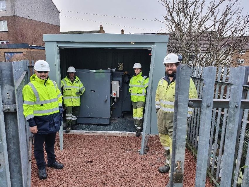
Figure 15 shows the type of modelling results we were able to extract, using Scheme 1 as an
example. The plots show the amount of active and reactive power flow that can be controlled down
the feeder between Crescent Road and Bingo Club substation by adjusting the active power set
points of the SST located at Crescent Road. The limitation occurs at active power set points above
100kW, where the Crescent Road LV busbar voltage starts to exceed the upper 10% statutory
limit. Tapping the transformer at the Bingo Club to reduce the LV voltage by minus 2.5% can be
22
Level of confidentiality: Take care of the environment.
Printed in black and white and only if necessary.
Internal UseLV Engine Project Progress Report - 2020
used to increase this threshold to above 150kW. The SST can effectively control the loading of the
Bingo Club transformer to between 20% and 60% demonstrating the capacity sharing.
Figure 13 Voltage heatmap snapshot (at the period of Bingo Club substation maximum demand)
Figure 14 Cable loadings heat map (at the period of Bingo Street maximum demand)
23
Level of confidentiality: Take care of the environment.
Printed in black and white and only if necessary.
Internal UseLV Engine Project Progress Report - 2020
Figure 15- Increase in power transfer between two neighbouring substations in Wrexham with -2.5% tap at
conventional substation
Wrexham – Control System Development
Several control methodologies for capacity sharing between SST and a conventional transformer
which are located at two neighbouring substations (as shown in Figure 16) were developed and
tested on the Wrexham model. The control methodologies demonstrated in various network
conditions over a 24-hour period using the load data monitored for individual feeders in Wrexham.
A script was set up to run through a 24-hour load profile with load flows being conducted at each
hour (quasi-dynamic simulation). Figure 17 shows a flowchart for one of the control methodologies
which has been developed and is currently being assessed.
Figure 16 Capacity sharing between two neighbouring substations
24
Level of confidentiality: Take care of the environment.
Printed in black and white and only if necessary.
Internal UseYou can also read