Nanosecond-precision Time-of-Arrival Estimation for Aircraft Signals with low-cost SDR Receivers - arXiv
←
→
Page content transcription
If your browser does not render page correctly, please read the page content below
Nanosecond-precision Time-of-Arrival Estimation for
                                                           Aircraft Signals with low-cost SDR Receivers
                                                   Roberto Calvo-Palomino                                    Fabio Ricciato                                  Blaz Repas
                                                 IMDEA Networks Institute, Spain                    University of Ljubljana, Slovenia            University of Ljubljana, Slovenia
                                                  University Carlos III of Madrid                      fabio.ricciato@fri.uni-lj.si                 br9404@student.uni-lj.si
                                                    roberto.calvo@imdea.org

                                                                              Domenico Giustiniano                               Vincent Lenders
                                                                          IMDEA Networks Institute, Spain                      armasuisse, Switzerland
arXiv:1802.07016v1 [eess.SP] 20 Feb 2018

                                                                          domenico.giustiniano@imdea.org                    vincent.lenders@armasuisse.ch

                                           ABSTRACT                                                                     RTL-SDR dongle [3]. We show that existing TOA estimation ap-
                                           Precise Time-of-Arrival (TOA) estimations of aircraft and drone              proaches based on a cross-correlation with a reconstructed signal
                                           signals are important for a wide set of applications including air-          template are sub-optimal in the particular context of Mode S signals.
                                           craft/drone tracking, air traffic data verification, or self-localization.   In fact, the loose tolerance margins allowed by the specifications on
                                           Our focus in this work is on TOA estimation methods that can                 the shape and position of each individual symbol within the packet
                                           run on low-cost software-defined radio (SDR) receivers, as widely            (up to ± 50 ns) adds uncertainty to the reconstruction of the whole
                                           deployed in Mode S / ADS-B crowdsourced sensor networks such as              packet waveform at the receiver.
                                           the OpenSky Network. We evaluate experimentally classical TOA                   We propose two alternative methods that improve the precision
                                           estimation methods which are based on a cross-correlation with a             and at the same time reduce the computational load.We test different
                                           reconstructed message template and find that these methods are               variants of TOA estimation on real-world signal traces captured
                                           not optimal for such signals. We propose two alternative methods             with RTL-SDR, which is currently the cheapest SDR device on the
                                           that provide superior results for real-world Mode S / ADS-B signals          market and widely used by crowdsourced sensor networks. Our
                                           captured with low-cost SDR receivers. The best method achieves a             results show that the best proposed method delivers TOA estimates
                                           standard deviation error of 1.5 ns.                                          with a standard deviation error of 1.5 ns. We further identify the
                                                                                                                        limited dynamic range of the RTL-SDR device (less than 50 dB with
                                                                                                                        8-bit analog-to-digital converter (ADC) and fixed automatic-gain
                                           1    INTRODUCTION                                                            controller (AGC)) as the main performance bottleneck, and show
                                           Aircraft and unmanned aerial vehicles continuously transmit wire-            that sub-nanosecond precision is achievable for signals that are not
                                           less signals for air traffic control and collision avoidance purposes.       clipped due the limited dynamic range of the device.
                                           These signals are either sent as responses to interrogations by sec-
                                           ondary surveillance radars (SSR) or automatically on a periodic              2     BACKGROUND
                                           basis (ADS-B). Both types of signals are transmitted over the so-            This section provides background on aircraft signals which we
                                           called Mode S data link [12] on the 1090 MHz radio frequency.                rely on to estimate the TOA, and the limitations of classical TOA
                                              Over the last few years, sensor network projects have emerged             estimation methods.
                                           which collect those signals using a crowd of low-cost software-
                                           defined radio (SDR) receivers such as e.g. the OpenSky Network [20],
                                           Flightaware [5], Flightradar24 [6] and many others. These sensor             2.1     Mode S signal format
                                           networks can leverage the time-of-arrival (TOA) of Mode S sig-               Hereafter we briefly review the physical-layer format of SSR Mode
                                           nals for various kinds of applications, including aircraft localiza-         S [18] reply and ADS-B messages transmitted by aircrafts on the
                                           tion [20, 22], air traffic data verification [13, 16, 17, 19, 21], and       1090 MHz channel. Both packet formats consist of a preamble of
                                           self-localization [15]. In those applications, a set of cooperating          8 µs plus a payload of 112 or 56 bits (only for other SSR Mode S
                                           receivers measure locally the TOA of the arriving signals and then           replies) sent at 1 Mbps rate, for a total duration of 120 µs or 64
                                           send these data to a central computation server. By joint process-           µs, respectively. The information bits are modulated with a simple
                                           ing the TOA of the same signal arriving at different receivers, the          Binary Pulse Position Modulation (BPPM) scheme as illustrated in
                                           central server is able to estimate the location of the transmitter, the      Fig. 1: the symbol period of 1 µs is divided into two “chips" of 0.5 µs,
                                           location of the receivers, or the exact time when the signal was             and the high-to-low and low-to-high transitions encode bits “1" and
                                           transmitted.                                                                 “0", respectively. It is clear from Fig. 1 that the BPPM modulation
                                              The accuracy of these applications heavily depends on the preci-          produces two types of pulses of different duration, denoted hereafter
                                           sion of the TOA estimation, and in order to estimate positions up to         as “Type-I" and “Type-II". Type-I pulses have a nominal duration of
                                           a few meters it is necessary to estimate the TOA with nanosecond             one chip period and are produced by the bit sequences “00", “11"
                                           precision. The goal of this work is to provide a method for the              and “10". The preamble consists of four Type-I pulses. On the other
                                           TOA estimation of Mode S signals that delivers nanosecond-level              hand, Type-II pulses have a nominal duration of two chip periods
                                           precision even with low-cost SDR receivers, such as the widespread           and are produced exclusively by the “01" sequence.
preamble payload modified receiver
8 µsec 112 µsec
with HPTOA function
IQ samples sm decoded bits pm
legacy
receiver
1 µsec 1 µsec (e.g.
dump1090)
“1” symbol “0” symbol
High-‐Precision
high-precision
TOA
es?ma?on
timestamp tm
Type-I peaks Type-II peak
Figure 2: Block diagram of improved receiver with high-
precision TOA estimation.
… …
time
3 OUR TOA ESTIMATION METHODS
Figure 1: Mode S packet structure with a binary PPM modu- In this section we describe the general approach to TOA estimation
lation. based on the decoded payload and received signal samples, and
then present the different TOA estimation algorithms that were
tested.
3.1 Signal acquisition architecture
On average, we expect approximately 112/2 = 56 Type-I and In the software domain, the high-precision TOA estimation process
112/4 = 28 Type-II pulses for a payload of 112 bits. can be seen as an additional function that is optionally called within
The real-valued baseband signal is then modulated on the 1090 the receiver and remains independent from the main decoding pro-
MHz carrier frequency and transmitted over the air. On the receiver cess. As such, it can be implemented on top of any legacy receiver,
side, the decoding process relies exclusively on the signal amplitude, including but not limited to the widely adopted open-source tool
since in BPPM the signal phase carries no information. dump1090 [1]. The overall block diagram of the proposed scheme
is exemplified in Fig. 2. The legacy receiver takes as input a stream
of complex in-phase and quadrature (IQ) samples collected at sam-
2.2 Limitation of standard TOA methods pling rate fs (for RTL-SDR hardware fs = 2.4 MHz). The legacy
The standard “course book" approach to TOA estimation in the receiver seeks to detect and decode the incoming packet and, if
Additive White Gaussian Noise (AWGN) channel is a correlation successful, provides as output the decoded bit sequence pm along
filter [14]: the received signal is cross-correlated with a known with the indication of the leading IQ sample of the detected packet.
template corresponding to the source signal, and the point in time Denote by sm the sequence of complex IQ samples corresponding
maximizing the cross-correlation module is taken as TOA estimate. to the whole packet. The sequence includes approximately 300
The correlation method relies on the assumption that the source samples since we also pick a few samples immediately before and
signal can be reconstructed very precisely at the receiver, based on after the packet in order to mitigate edge effects. The sample vector
the signal specifications and knowledge of the payload bits pm . sm and the decoded bit vector pm represent the input to our TOA
Under this assumption, the correlation method represents the Max- estimation block.
imum Likelihood Estimator (MLE) [14]. However, this assumption
is problematic in the particular case of real-world Mode S signals. 3.2 Proposed methods: CorrPulse and
In fact, the standard specifications tolerate up to ±50 ns jitter in the PeakPulse
position of each individual pulse within the packet: such high tol- Hereafter we describe two novel TOA estimation algorithms specif-
erance value is practically negligible for the decoding process, but ically developed for Mode S signals. For a generic packet m we
not for the task of determining the TOA with nanosecond precision. shall denote by Km the total number of pulses in the whole packet
As to the shape of each pulse, tolerance values of 50 ns are allowed (preamble and payload). The input vector of complex samples sm is
for the pulse duration and rise time and up to 150 ns for the decay preliminarily upsampled by a factor N and transformed into vector
time, while pulse amplitude may vary up to 2 dB (approximately sm′ (for a review of upsampling process see e.g. [10]). To illustrate,
60%). Such loose tolerance margins introduce uncertainty in the Fig. 3 plots an excerpt of the amplitude of both vectors, namely
prediction of the shape and position of the pulses in the source ′ (bottom plot), for a generic packet found in
|sm | (top plot) and sm
signal. Considering that Mode S signals are typically received with a real-world trace.
high SNR, such an uncertainty might well prevail over the effect of The key aspect of the proposed algorithms is that the actual
additive noise. Consequently, the correlation-based approach with temporal position τ̂k of the generic kth pulse within the packet
a known packet template is no longer guaranteed to be optimal, is estimated independently from other pulses, with no need to re-
motivating the quest for alternative, more precise methods. construct a template for the whole packet. For each pulse k ≥ 2,
24.1 Other methods for comparison
4.1.1 Correlation with whole-packet template: CorrPacket. This
is the canonical cross-correlation method with a known signal
template.
For every packet m, the whole packet template is reconstructed
from the decoded bits pm and then cross-correlated with the am-
plitude of the incoming signal. Here also, upsampling by a factor
N is adopted to achieve sub-sample precision. Within the template,
the kth pulse is positioned at the nominal time τk . As to the pulse
shapes, we have tested two different variants: “Rectangular" (R), and
“Smoothed" (S). The two versions will be denoted by CorrPacket/R
and CorrPacket/S. The rectangular pulses have a nominal duration
of 0.5 µs and 1 µs for Type-I and Type-II pulses, respectively, and
zero rise/decay times. The rectangular pulse mask is represented ex-
clusively by “0" and “1" values, hence multiplications with another
vector reduce to element selection, which saves on computation
load. The “Smoothed" shape corresponds to the output of a low-
pass filter with passband of 2.4 MHz—matched to the bandwidth of
the RTL-SDR receiver—when the input signal is a nominal Type-
I/Type-II pulse with the minimum decay/rise time of 50 ns as per
Figure 3: Example of received signal amplitude correspond-
specifications [11].
ing to the preamble and initial payload of a real ADS-B
packet. Original samples at fs = 2.4 MHz (top, red circles) 4.1.2 Existing dump1090 based implementations. We also evalu-
and corresponding upsampled version (bottom, blue line). ate the precision of the timestamp reported by the mutability fork
of the open-source tool dump1090 [1]. Furthermore, we test on our
traces also the method adopted by Eichelberger et al. in a recent
def
ACM SenSys’17 paper [15] which is also based on dump1090. Code
we compute the individual shift ∆τk = τ̂k − τk , i.e., the difference inspection revealed that this method is based on a cross-correlation
between the estimated and nominal pulse position relative to the (implemented in frequency domain) with a partial packet template
(estimated) position of the first pulse. Finally, the pulse shifts are consisting of the preamble plus one quarter of the payload, with
averaged in order to obtain the final TOA estimate: rectangular pulses and upsampling factor N = 25.
Km
1 Õ
4.2 Testbed setup
tˆ = τ̂1 + ∆τk (1)
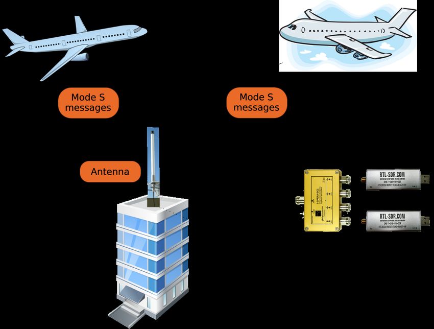
Km − 1 The experimental setup consists of two identical sensors connected
k =2
to a single antenna through a power splitter and cables of identical
The two proposed variants differ in the way individual pulse length. The sensors are located on the roof of a building as Figure 4
position estimates are obtained, and which type(s) of pulses are con- shows. Every sensor consists of one RTL-SDRv3 “Silver" model [4]
sidered. In the first variant, labeled CorrPulse, each pulse position is attached to a Raspberry Pi-3 [2]. The AGC gain is set to a fixed
determined through pulse-level cross-correlation of the upsampled value, manually tuned to maximize the packet decoding rate. The
′ with the corresponding nominal pulse shape. Both Type-I
vector sm sampling rate was set to fs = 2.4 MHz, the maximum value that our
and Type-II pulses are considered in the final averaging. setup is able to acquire with sample losses. Every I and Q sample is
In the second variant, labeled PeakPulse, individual pulse posi- represented with 8 bit. The full stream of IQ samples are recorded
tions are determined by simply picking the local maximum point one and processed multiple times offline. Our results are based on
value within the pulse interval, with no cross-correlation operation. a sample trace of 5 minutes collected in Thun (Switzerland) on
In this variant only Type-I pulses are considered, while Type-II 02-Aug-2017 at time 09:41. The number of ADS-B packets that are
pulses are ignored. This is motivated by the fact that Type-II pulses correctly decoded at both sensors by the dump1090 open-source tool
have lower curvature, hence their local peaks cannot be identified [1] amount to 26445 from 59 different aircraft.
as reliably as for Type-I pulses.
4.3 Evaluation Metrics
4 EVALUATION METHODOLOGY In this section, we briefly describe the methodology adopted to
This section describes how we evaluate our new methods. First, we assess the precision of the different TOA estimation methods. The
introduce the other competing methods taken as reference for the problem is not trivial, since our receivers are not synchronized and
comparison. Then, we present the testbed setup with commercial the “true" TOA is unknown. Therefore, we developed an evaluation
low-cost hardware. Finally, we provide details on the procedure method which allows us to quantify the TOA precision without
adopted to empirically assess the precision of the TOA measurement a ground truth. Denote by tm,i the true absolute arrival time of
methods in the given setup. packet m to receiver i and by tˆm,i the corresponding measured TOA
3(a) Low upsampling factor
Figure 4: Experimental setup. Two identical receivers con-
nected to the same antenna via a splitter are collecting Mode
S messages sent by aircraft.
(by the method under test). In general, the measured value tˆm,i is
affected by two distinct sources of error, namely clock error and
measurement noise:
tˆm,i = tm,i + ξ i (t)|t =tm,i + ϵm,i . (2)
The term ξ i (t) models the clock error between the receiver clock
and the absolute time reference, and can be modeled by a slowly-
varying function of time. Its magnitude depends on the hardware
characteristics of the device, and specifically on the stability of the
local oscillator.
The term ϵm,i represents the measurement noise in the TOA
estimation process and is modeled by a random variable with zero
mean and variance σTOA 2 . The precision of the TOA estimate, defined (b) High upsampling factor
as the reciprocal of the noise variance, is independent of the clock
error. The goal of the present study is to reduce σTOA 2 . The prob-
Figure 5: ECDF of ∆ϵ residuals.
lem of counteracting the clock error component remains outside
the scope of the present contribution. Here it suffices to mention
that the clock error can be mitigated by adopting receivers with error, i.e. a bias term that can be estimated and removed in order to
GPS Disciplined Oscillators (GPSDO), or it can be estimated and estimate the error variance σ∆ϵ 2 . We do so by modeling the slowly-
compensated in post-processing [7–9]. varying function ∆ξ i (t) by a polynomial whose coefficients are
Hereafter we illustrate the methodology to experimentally quan- estimated by standard order-recursive Least Squares (refer to [14,
tify the empirical TOA standard deviation σ̂TOA notwithstanding Chapter 8] for details). After removing the estimated clock error
the presence of a non-zero clock error component. First, we need component, we obtain a set of residuals {∆ϵ }. Their Mean Square
to get rid of the unknown true absolute arrival time tm,i in Equa- Error (MSE) represents an empirical estimate of twice the TOA
tion (2). Since we use two identical receivers attached to the same variance MSE ∆ϵ = 2 · σTOA 2 . Accordingly, their Root Mean Square
antenna, we can set tm,1 = tm,2 = tm and subtract the TOA mea- Error (RMSE) provides a direct empirical estimate of the TOA error
surements at the two sensors to obtain the corresponding time standard deviation, formally:
difference:
ˆ m def 1
∆t = tˆm,2 − tˆm,1 = ∆ξ (tm ) + ∆ϵm (3) σ̂TOA = √ RMSE ∆ϵ ≈ 0.7 · RMSE ∆ϵ .
def
2
wherein ∆ξ (t) = ξ 2 (t) − ξ 1 (t) denotes the compound clock error,
def
and ∆ϵm = ϵm,2 − ϵm,1 the compound measurement error with 5 NUMERICAL RESULTS
2 = 2σ 2 . At short time-scales, within the coherence
variance σ∆ϵ We now present the results on the precision of the different TOA
TOA
time of the process ∆ξ (t), the clock error represents a systematic estimation methods as evaluated in our testbed.
4estimation method σ̂TOA [nanoseconds]
all packets L M H
legacy dump1090 45.20 44.94 45.19 45.43
SenSys’17, N = 25 5.90 6.11 5.88 5.78
CorrPacket/R, N = 25 4.98 5.48 4.85 4.94
CorrPacket/R, N = 83 2.14 3.04 1.78 2.35
CorrPacket/S, N = 83 2.07 3.00 1.68 2.275
CorrPulse/R, N = 25 1.89 2.75 1.56 1.86
CorrPulse/R, N = 83 1.63 2.72 1.04 1.77
CorrPulse/S, N = 83 1.51 2.60 0.79 1.77
PeakPulse, N = 25 2.20 3.36 1.70 2.23
Figure 6: TOA standard dev. error vs. upsampling factor N PeakPulse, N = 83 2.12 3.44 1.62 2.17
Table 1: Empirical estimates of TOA error standard devia-
tion σ̂TOA .
5.1 Error distribution
In Fig. 5 we plot the Empirical Cumulative Distribution Function
(ECDF) of the residuals ∆ϵ’s obtained with different TOA estimation
methods for all the packets in the test trace. The corresponding
values of the TOA error standard deviation σ̂TOA are reported in
the leftmost column of Table 1.
For those applications where the computation load is of con-
cern, it is relevant to investigate the performance of the different
methods with moderate value of the upsampling factor (N = 25).
For CorrPacket and CorrPulse, we consider the rectangular pulse
shape with binary 0/1 values, due to lower computation load. Refer-
ring to Fig. 5(a), we observe that the proposed PeakPulse algorithm
achieves a RMSE ∆ϵ = 3.15 ns, less than half the value of the canoni-
cal CorrPacket/R method. It is remarkable that such good result was
obtained with no cross-correlation operation. Fig. 6 shows σ̂TOA Figure 7: Absolute error |∆ϵm | vs. packet strength γm .
for different values of the upsampling factor N . We observe that
the precision of the proposed methods PeakPulse and CorrPulse/R
improves faster than CorrPacket/R with increasing N . These results In Fig. 7, we plot for each individual packet m the absolute value of
indicate that PeakPulse should be preferred when computation load the residual error |∆ϵm | obtained with CorrPulse/S (N = 83) against
is at premium. def γ +γ
the mean signal strength between the two sensors γm = m, 1 2 m, 2 .
Next we consider applications that enjoy abundant computation Each packet is classified into one of three classes: packets with
power, for which the main goal is to maximize precision and compu- γm ≤ 0.04 are labeled by “L", packets with mini=1,2 βm,i ≥ 10
tation load is not of concern. For these, it is convenient to consider are labeled with “H", and all remaining packets are labeled with
higher upsampling factors (N = 83 in our case) and, for the cross- “M". The three classes are marked respectively with black, red and
correlation methods, the more elaborated “Smoothed" pulse shape. blue markers in Fig. 7. The estimated TOA error standard deviation
The latter matches more closely the pulse shape passed through obtained by each method for each class are reported in Table 1. On
the RTL-SDR front-end, leading to slightly higher precision than one extreme, timing estimates for “L" packets with lower strength
the simpler “Rectangular" shape, as can be verified from Table 1. are impaired by quantization noise. On the other extreme, packets
The ECDF of the residuals ∆ϵ’s for these methods are plotted in received with high strength are subject to ADC clipping, a form
Fig. 5(b). It can be seen that the proposed CorrPulse/S method is of distortion that clearly degrades timing precision. As expected,
more precise than the classical CorrPacket/S method, and achieves these two classes yield higher error with all methods. Between the
RMSE ∆ϵ = 2.16 ns corresponding to σ̂TOA = 1.51 ns. two extremes, the strength of “M" packets fits well the dynamic
range: for these, the proposed method achieves σ̂TOA = 0.79 ns.
5.2 Error vs. signal strength In our traces, less than 60% of all packets fall into class “M". With
In the following, we investigate the impact of signal strength on better hardware, and specifically with more ADC bits and larger
the TOA error obtained with the most precise method, namely Cor- dynamic range, it would be possible to tune the AGC gain so as to
rPulse/S with N = 83. For a generic packet m and sensor i, we denote increase the fraction of packets falling in this class, thus improving
by γm,i the average of the squared pulse height over all pulses — an the overall precision.
indicator of the arriving packet strength. Furthermore, we denote The above results indicate that the received packet metrics γm,1
by βm,i the number of pulses that are clipped in the receiver due to and βm,i can be used to provide, for each individual TOA mea-
one or more of the corresponding IQ samples saturating the ADC. surement tˆm,i , also an indication of the expected precision, i.e., of
5receiver, the CorrPulse/S achieves sub-nanosecond precision. It can
Quantiles of Input Sample
Quantiles of Input Sample
20 20
All packets L-class
be expected that precision can be further improved with better hard-
10 10
ware. The PeakPulse method has been implemented in C, integrated
0 0 in the dump1090 receiver and is released as open-source1 .
1 http://github.com/openskynetwork/dump1090-hptoa
-10 -10
-20
-4 -2 0 2 4
-20
-4 -2 0 2 4
ACKNOWLEDGMENTS
Standard Normal Quantiles Standard Normal Quantiles
This work has been funded in part by the Madrid Regional Gov-
ernment through the TIGRE5-CM program (S2013/ICE-2919). We
Quantiles of Input Sample
Quantiles of Input Sample
20 20
M-class H-class
10 10
would like to thank Manuel Eichelberger from ETH Zurich for shar-
ing the code we used in our evaluation for comparison purposes.
0 0
-10 -10
REFERENCES
[1] 2016. dump1090, https://github.com/mutability/dump1090. https://github.com/
-20 -20 mutability/dump1090.
-4 -2 0 2 4 -4 -2 0 2 4 [2] 2016. Raspberry Pi 3 Model B, https://www.raspberrypi.org/products/raspberry-
Standard Normal Quantiles Standard Normal Quantiles pi-3-model-b/.
[3] 2016. Silver v3 specifications. http://www.rtl-sdr.com/buy-rtl-sdr-dvb-t-dongles/.
[4] 2017. RTL-SDR dongle v3, http://www.rtl-sdr.com/buy-rtl-sdr-dvb-t-dongles/.
Figure 8: Quantile-quantile plot of empirical errors ∆ϵ vs. [5] 2018. FlightAware. http://www.flightaware.com/.
normal distribution. [6] 2018. FlightRadar24. https://www.flightradar24.com/.
[7] F. Ricciato, S. Sciancalepore, F. Gringoli, N. Facchi and G. Boggia. 2018. Position
and Velocity Estimation of a Non-cooperative Source From Asynchronous Packet
2 affecting each individual measurement. In Arrival Time Measurements. IEEE Trans. on Mobile Computing (2018).
the error variance σ̂m,i [8] G. de Miguel, J. Portas, J. Herrero. 2005. Correction of propagation errors in Wide
this way, algorithms that take TOA measurements as input (e.g., Area Multilateration systems. In Proc. of 6th European Radar Conference.
for position estimation) have the possibility to weight optimally [9] G. Galati, M. Leonardi, I.A. Mantilla-Gaviria and M. Tosti. 2012. Lower bounds
of accuracy for enhanced mode-S distributed sensor networks. IET Radar, Sonar
each individual input measurement, as done e.g. in Weighted Least and Navigation (2012).
Squares methods [23]. [10] Fred J. Harris. 2004. Multirate Signal Processing for Communication Systems.
Prentice Hall.
Finally, we find that within each class the empirical error distribu- [11] ICAO. 2007. Aeronautical Communications, Volume IV, Surveillance and Collision
tion is very well approximated by the Gaussian distribution, as seen Avoidance Systems. (July 2007).
from the normal Q-Q plots in Fig. 8. This justifies the adoption of [12] ICAO 2008. Technical Provisions for Mode S Services and Extended Squitter. ICAO.
Doc 9871, First Edition.
Least Squares (LS) methods for position estimation problems based [13] K. Jansen, M. Schäfer, D. Moser, V. Lenders, C. Pöpper, , and J. Schmitt. 2018.
on input TOA measurements [7], since for normally distributed in- Crowd-GPS-Sec: Leveraging Crowdsourcing to Detect and Localize GPS Spoofing
put errors the LS solution coincides with the Maximum Likelihood Attacks. In IEEE Symposium on Security and Privacy (S&P).
[14] S. M. Kay. 1993. Fundamentals of Statistical Signal Processing, vol. 1, Estimation
estimate. Theory. Prentice-Hall.
[15] S. Tanner M. Eichelberger, K. Luchsinger and R. Wattenhofer. 2017. Indoor
6 CONCLUSIONS AND OUTLOOK Localization with Aircraft Signals. In ACM SenSys.
[16] V. Lenders M. Strohmeier and I. Martinovic. 2015. Lightweight Location Verifica-
We have presented two variants of a novel TOA estimation method tion in Air Traffic Surveillance Networks. In ACM Cyber-Physical System Security
Workshop (CPSS).
for Mode S signals that does not rely on long cross-correlations [17] D. Moser, P. Leu, V. Lenders, A. Ranganathan, F. Ricciato, and S. Capkun. 2016.
with the template of a full packet. The most precise variant, namely Investigation of Multi-device Location Spoofing Attacks on Air Traffic Control
CorrPulse/S, involves only short cross-correlation operations on and Possible Countermeasures. In ACM Conference on Mobile Computing and
Networking (Mobicom).
individual pulses. The other variant, namely PeakPulse, is lighter to [18] RTCA 2011. Minimum Operational Performance Standards for Air Traffic Control
compute, involves no cross-correlation operation and works well Radar Beacon System / Mode Select (ATCRBS / Mode S) Airborne Equipment. RTCA.
also with moderate upsampling factors. DO-181E.
[19] M. Schäfer, M. Strohmeier, V. Lenders, and J. Schmitt. 2015. Secure Track Verifi-
We have shown that such algorithms can achieve TOA estimates cation. In Security and Privacy (S&P), 2015 IEEE Symposium on.
with nanosecond-level precision even with real-world signals cap- [20] M. Schäfer, M. Strohmeier, I. Martinovic V. Lenders, and M. Wilhelm. 2014. Bring-
ing Up OpenSky: A Large-scale ADS-B Sensor Network for Research. In 13th
tured with the cheapest SDR hardware that is currently available, ACM/IEEE Int. Conf. on Information Processing in Sensor Networks (IPSN’14).
namely RTL-SDR. A closer look at the test results reveals that the [21] M. Strohmeier, V. Lenders, and I. Martinovic. 2015. On the Security of the
main limiting factor for the achievable TOA precision with RTL- Automatic Dependent Surveillance-Broadcast Protocol. IEEE Communications
Surveys and Tutorials Journal (2015).
SDR is the limited dynamic range — less than 50 dB with 8-bit [22] M. Strohmeier, V. Lenders, and I. Martinovic. 2018. A k-NN-based Localiza-
ADC and fixed AGC — resulting in a large fraction of packets being tion Approach for Crowdsourced Air Traffic Communication Networks. IEEE
clipped or drowned into quantization noise. For packets that are Transactions on Aerospace and Electronic Systems (TAES) (2018).
[23] Tilo Strutz. 2010. Data fitting and uncertainty: A practical introduction to weighted
received with signal strength well within the dynamic range of the least squares and beyond. Vieweg and Teubner.
6You can also read