Crystal orientation and crystal structure of paramagnetic α Al under a pulsed electromagnetic field - Nature
←
→
Page content transcription
If your browser does not render page correctly, please read the page content below
www.nature.com/scientificreports
OPEN Crystal orientation and crystal
structure of paramagnetic α‑Al
under a pulsed electromagnetic
field
Qingwei Bai1,3*, Jun Wang2*, Shuqing Xing2*, Yonglin Ma2 & Xinyu Bao2
The intermittent electromagnetic fields with a large ∂B/∂t can enhance the properties of
ferromagnetic materials and significantly affect paramagnetic materials. In this study, the effect of
a pulsed electromagnetic field on the crystal orientation of the primary phase and microstructure
evolution of an Al–Zn–Mg–Cu alloy was investigated. A mathematical model was developed to
describe crystal rotation under a pulsed electromagnetic field. The model predictions show that the
magnetic energy difference generated by the magnetic anisotropy of the primary crystal produces
primary phases with sizes of 225–100 μm to rotate into a preferred orientation. The lattice
constant, the interplanar spacing, and the microstrain increase with the duty cycle of the pulsed
magnetic field, especially for the (111) and (200) crystal planes. This study provides preliminary
theoretical support for using pulsed electromagnetic fields to control the orientation and microscopic
properties of materials.
Some organic and inorganic materials exhibit unusual phenomena under electromagnetic fields. Grain rotation,
deformation, and orientation changes are generated in metallic materials during electromagnetic solidification
processing, and levitation and structural transformations are observed for nonferromagnetic materials. Thus,
the magnetic force is considered to be the main factor in materials processing. The magnetic force has two com-
ponents. The parallel component causes a magnet pulls ferromagnetic and paramagnetic materials and repels
diamagnetic materials. The rotational component results in the generation of a Lorentz force from the interaction
of the current and the external magnetic field. The parallel magnetic force is mainly used for magnetic separation,
magnetic levitation1, and to measure the magnetic susceptibility2. The magnetocrystalline anisotropy of materi-
als determines the magnetic susceptibilities in different crystal planes. Thus, the rotational magnetic force can
be used to construct materials with ideal crystal orientations and texture d istributions3–8. The magnetic anisot-
ropy is widely used to control crystal orientation, for example, to realize magnetic directional alignments of an
undoped Cu–O superconducting magnet and Zn film are achieved. For the FCC (face-centered-cubic) crystal,
when the magnetic susceptibility along the direction parallel to the c-axis of the unit crystal (χc ) is higher than
that perpendicular to the c-axis (χab), the unit crystal grows along the c-axis, which is parallel to the external
field, H9–11. Magnetic anisotropy in ion-doped materials results from single-ion anisotropy in the magnetic fi eld12.
Recently, Liu et al.13 investigated the influence of a magnetic field on the crystal orientation and magnetic
properties of Fe-4.5 wt% Si. The crystal orientation of the Fe-4.5 wt% Si alloy was rotated into the axis, and
strong Goss texture was obtained under a 6-T high static magnetic field. Zhong et al.14 found that an Al-4.5 Cu
free crystal rotated in the melt state to align with the crystallographic axis in the direction of the magnetic
field. Increasing the magnetic field intensity resulted in a random-–– transformation of the
(Tb, Dy) Fe2 orientation15. For crystal orientation applications, Asai et al.16 summarized the anisotropy values
1
Key Laboratory of Integrated Exploitation of Bayan‑Obo Multi‑Metallic Resources, Inner Mongolia University
of Science and Technology, No. 7 Arding Street, Baotou 014010, Inner Mongolia, People’s Republic of
China. 2School of Material and Metallurgy, Inner Mongolia University of Science and Technology, No. 7 Arding
Street, Baotou 014010, Inner Mongolia, People’s Republic of China. 3Inner Mongolia Autonomous Regional
Engineering Technology Research Center of Sustainable Exploitation of Rare Earth Secondary Resources, Inner
Mongolia University of Science and Technology, Baotou 014010, People’s Republic of China. *email: abcqingwei@
imust.edu.cn; jwkwj@imust.cn; xingshuqing@imust.edu.cn
Scientific Reports | (2020) 10:10603 | https://doi.org/10.1038/s41598-020-67352-4 1
Vol.:(0123456789)
www.nature.com/scientificreports/
Figure 1. Central solidified structure of 7A04 aluminum: (a) untreated and (b) treated with 20% pulse duty
cycles20. ©2017 ASM International.
of several nonmagnetic materials after electroplating, vapor deposition, solidification, and heat treatment under
a high magnetic field. Ferreira et al.17 mathematically modeled the crystal orientation during nucleation and
growth processes under a high magnetic field. However, fundamental research studies have not been performed
to further explain and predict these phenomena.
Pulsed magnetic fields excite an intermittent noncontact electromagnetic field with a large ∂B/∂t that can
significantly affect a solidified s tructure18,19. Compared with a steady-state DC magnetic field, the pulse width
of a pulsed magnetic field is on the order of milliseconds or microseconds and can produce a high magnetic
flux density. This pulsed electromagnetic effect can be used to prepare ferromagnetic, paramagnetic, and dia-
magnetic materials. Pulsed electromagnetic fields are convenient to use, have low energy consumption, and
produce good structural improvements and are therefore one of the most promising techniques for material
processing. We previously found20–22 that a pulsed electromagnetic field promoted the nucleation and solidified
structural transformation of paramagnetic Al–Zn–Mg–Cu alloys. A rose structure with a coarse grain size was
transformed into a fine and rounded spherical structure with improved strength and plasticity (see Fig. 1). A
pulsed electromagnetic field decreases the critical Gibbs free energy for nucleation to occur in a system, which is
an important factor in increasing the nucleation rate and refining grains. However, the mechanical properties of
materials depend strongly on the crystal orientation and microstructure. Lorentz force causes melt motion, and it
plays another role in melt at the same time. From Lenz’s law, the rotation of an electrically conductive substance
in a magnetic field produces a Lorentz force from the interaction between the rotational motion and the ∂B⁄∂t
generated to suppress particle rotation. The Lorentz force reduces the influence of particle displacement on the
orientation. The distribution of crystal defects, such as vacancies, dislocations, and stacking or twin faults, can
produce microstrain in the microstructure. A high dislocation density and significant microstrain in the crystal
phase increases the total strength and plasticity of the crystal23,24. In this paper, a pulsed electromagnetic field was
applied during the solidification of an Al–Zn–Mg–Cu alloy. The graphical abstracts about the crystal rotation and
microstructure evolution under a pulsed electromagnetic field were exhibited in Fig. 2. The formation mechanism
of the preferred crystal orientation under the Lorentz force was theoretically analyzed, and a mathematical model
for the rotation of the primary phase under a pulsed magnetic field was constructed. A method was proposed for
controlling the crystal anisotropy during solidification, and the evolution rule of the microstructure was deter-
mined in terms of the lattice constant, the microstrain, etc. This study provides a theoretically based mechanism
by which pulsed electromagnetic field processing technology improves solidified structures.
Experiment and process
The test material was Al–Zn–Mg–Cu, a superhard aluminum alloy used in aerospace applications. The chemi-
cal composition of the alloy is listed in Table 1. This material has a wide solid–liquid phase region, a liquidus
temperature of 654 °C, and a complete solidus temperature of 528 °C. Figure 3 shows the experimental device,
which consists of a pulsed electromagnetic field generator (comprising a water-cooled induction coil and an
iron core), a pulsed power supply, a resistance heater, a cooling system, an induction melting furnace, a crystal-
lizer, and a tundish. The crystallizer was preheated to 500 °C by an internal resistance heater, and the alloy was
melted in the medium-frequency induction melting furnace at 800 °C for 10 min. The resistance heater was then
removed from the crystallizer. The melt was poured into the crystallizer (Φ = 60 mm) and subjected to pulsed
electromagnetic treatment until the temperature dropped below 300 °C. The water cooling device was activated
to rapidly cool the sample. The parameters of the electromagnetic pulse were as follows: a peak current of 200 A,
a pulse frequency of 20 Hz, a magnetic flux density of 153 mT, and a pulse duty cycle (the time ratio between
the pulse discharge and the total pulse period for each period) of 20% or 40%. The solidified specimens were
analyzed using X-ray diffraction (XRD). A three-dimensional finite element method (3D-FEM) was employed
to investigate solidification under the pulsed electromagnetic field. A mathematical-physical model, including
the pulse coil, copper mold, and melt, was established. The Lorentz force was initially calculated using ANSYS
EMAG and used as a source in ANSYS FLUENT to calculate the flow and temperature fields. The detailed gov-
erning equations and associated boundary conditions can be found in the l iterature21.
Scientific Reports | (2020) 10:10603 | https://doi.org/10.1038/s41598-020-67352-4 2
Vol:.(1234567890)
www.nature.com/scientificreports/
Figure 2. Crystal rotation and microstructure evolution under a pulsed electromagnetic fi
eld20. ©2017 ASM
International.
Si Cu Mg Zn Ti Al
0.09 1.92 2.45 5.22 0.04 Bal
Table 1. Alloy chemical composition (wt%).
Figure 3. Schematic and 3D simulation model of an electromagnetic pulse c aster20. ©2017 ASM International.
Scientific Reports | (2020) 10:10603 | https://doi.org/10.1038/s41598-020-67352-4 3
Vol.:(0123456789)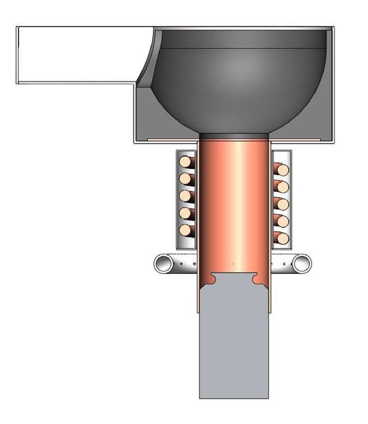
www.nature.com/scientificreports/

                                      Figure 4.  Temperature field (a) before and (b) after pulsed electromagnetic field application; and flow field (c)
                                      before and (d) after pulsed electromagnetic field application.

                                      Preferred crystal orientation
                                      Solidification environment under pulsed magnetic field.                 Figure 4 shows the transient numerical
                                      simulation results of the flow and temperature fields of the longitudinal melt section before and after applying
                                      the pulsed electromagnetic field. In the absence of the pulsed magnetic field, the heat flux is directed from the
                                      center to the edge of the melt, and two symmetric and opposite vortex rings form in the longitudinal section.
                                      The application of the pulsed electromagnetic field (initial temperature: 923 °C, duty cycle: 20%) induces forced
                                      convection in the melt, which decreases the temperature gradient. The primary phase nucleates and grows in
                                      the quasisteady environment. The eddy-current effect is weakened, which reduces the impact on analyzing the
                                      orientation process of the primary phase.

          Scientific Reports |   (2020) 10:10603 |               https://doi.org/10.1038/s41598-020-67352-4                                                4

Vol:.(1234567890)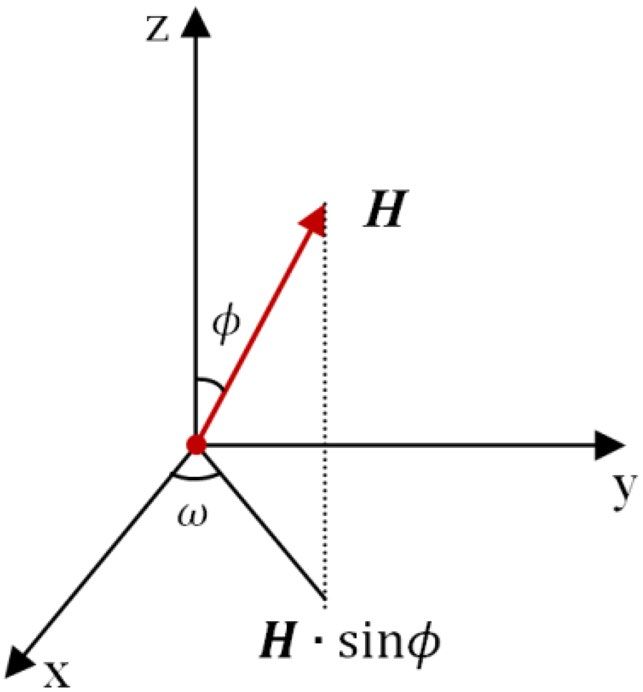
www.nature.com/scientificreports/

                            Figure 5.  XRD of solidified Al–Zn–Mg–Cu alloy.

                            Effect of pulsed electromagnetic field on crystal orientation. The shape and peak position of the
                            XRD patterns showed that the pulsed electromagnetic field treatment changed the microstructure and several
                            properties of the solidified alloy. The crystal structures of the Al–Zn–Mg–Cu alloy ingot cores were analyzed
                            using a D8 ADVANCE XRD diffractometer. The scanned section was perpendicular to the direction of the mag-
                            netic field, and the analysis results are shown in Fig. 5. The diffraction peak corresponding to the (111) plane
                            of α-Al crystals was enhanced by pulsed electromagnetic field treatment, indicating that applying the pulsed
                            magnetic field in the axial direction of the specimen promoted atom packing in the preferred  orientation.
                            However, the diffraction peak intensities corresponding to the (200) and (311) planes gradually decreased as the
                            pulse duty cycle increased, and the magnetic field gradually suppressed crystal growth along these two orienta-
                            tions. Three conditions must be satisfied for a magnetic field to control grain orientation: (1) the atomic clusters
                            in the system must overcome the energy barrier to form a critical nucleus with radius r *; (2) the magnetization
                            energy must be higher than thermal fluctuations; and (3) the magnetic susceptibility in the  direction of
                            the alloy must be greater than along the a-, b-, and c-axes, i.e., Ea,b,c > E(111), such that the magnetization energy
                            difference causes the primary phase to rotate under the pulsed magnetic field, whereby the  orientation is
                            rotated toward the magnetic field. Preferential crystal growth mainly depends on the atomic arrangement order.
                            The close-packed (111) plane has the lowest surface energy and a compactness of up to 74%. Atoms always pref-
                            erentially arrange along low-energy planes, which are easy to stabilize. Atoms are arranged relatively loosely on
                            the (200) plane with a lower coordination number, which makes a crystal grow slowly along the  direction.
                                Tahashi et al.25 determined the crystal rotation angle from XRD data using the following equation:

                                                                                     (Ihkl × θhkl )
                                                                            θF =                                                              (1)
                                                                                           Ihkl
                            where θF is the angle between the (hk0) plane and the c-axis; θhkl is the angle between the (hkl) and (00n) planes;
                            and Ihkl is the XRD intensity of the (hkl) plane. Equation (1) was used to obtain the rotation angle of the crystal
                            from the XRD data (Fig. 6). Compared with the solidified specimen that was not subjected to a magnetic field,
                            the (111) crystal plane was rotated 13° toward the magnetic field direction under the 40% pulse duty cycle but
                            only 3° for under the 20% pulse duty cycle. Thus, the pulse duty cycle significantly impacted the rotation process.

                            Crystal rotation process. Neglecting thermal convection, the magnetic anisotropy of the crystal causes the
                            primary nucleus to rotate under the influence of a pulsed magnetic field. The magnetic susceptibility of the Al–
                            Zn–Mg–Cu alloy is a direction function of the magnetic field intensity, which can be expressed as χ = χ(ω, φ).
                            As the nucleus grows into the α-Al crystal, rotation is driven by the magnetic dipole moment induced by the
                            external magnetic field and the crystal magnetic anisotropy. When the magnetic field is parallel to the maximum
                            magnetic susceptibility, the magnetic energy provides less interaction for the rotation. As shown in Fig. 7, the
                            primary α-Al crystal was placed in an x–y orthogonal coordinate system, where the x-axis is defined as the easy
                            magnetization axis for the magnetic susceptibility χ1, and the y-axis is defined as the hard magnetization axis for
                            the magnetic susceptibility χ2. The projection angle between the easy magnetization axis and the magnetic field
                            direction on the x–y plane is ω . The magnetic field strength in the x–y plane is as follows:
                                                                             H x−y = H · sinφ                                                 (2)

                               Simplifying Eq. (2) using a two-dimensional vector analysis yields Eq. (3):

Scientific Reports |   (2020) 10:10603 |               https://doi.org/10.1038/s41598-020-67352-4                                               5

                                                                                                                                           Vol.:(0123456789)
www.nature.com/scientificreports/
B
n(111)
c
22° 11° a
9° b
(a) (b) (c)
Figure 6. Schematic of the primary crystal rotation. (a) 40% pulse duty cycle (b) 20% pulse duty cycle; and (c)
no applied magnetic field.
Figure 7. Coordinates of magnetic anisotropic crystal.
H x−y = H x cosω + H y sinω (3)
The total magnetization can be expressed as follows:
M s = M 1 cosω + M 2 sinω (4)
The magnetization along the easy magnetization axis and along the hard magnetization axis can be expressed
as Eqs. (5) and (6), respectively:
M 1 = χ1 H x−y cosω (5)
M 2 = χ2 H x−y sinω (6)
The α-Al crystal rotates and orients under the action of the magnetization force and reaches the equilibrium
position with the smallest magnetic energy. The magnetic energy can be expressed as follows:
Em (ω, H) = −1/2Vs H 2x−y [χ2 + (χ1 − χ2 )cos2 ω] (7)
When ω = 0, Em (0, H) = −1/2Vs χ1 H 2x−y (8)
When ω = π/2, Em (π/2, H) = −1/2Vs χ2 H 2x−y (9)
where Vs is the volume of a unit crystal, and the crystal rotation direction is determined by the paramagnetic
susceptibility along each crystal axis. Since χ1 > χ2, Em (0, H) < Em (π/2, H). The rotation of the primary α-Al
crystal in the magnetic field is affected by the inertial force, viscous force, Lorenz force and magnetization force,
among which the inertial moment and magnetic moment are the main driving force. The equation of rotation
motion caused by a magnetic field is expressed as Eq. (10)26:
Scientific Reports | (2020) 10:10603 | https://doi.org/10.1038/s41598-020-67352-4 6
Vol:.(1234567890)www.nature.com/scientificreports/
2 5 d2 ω dω 4 dω 1
ρr + 8πηr 3 + πr 5 GB2 + Vs B2 (χ1 − χ2 )sin2ω = 0
5 dt 2 dt 15 dt 2µ0 (10)
(Inertial force) (Viscous force) (Lorenz force) (Magnetization force)
G is the electrical conductivity, µ0 is the permeability of a vacuum, η is the viscosity, and r is the grain radius.
Assuming that the inertial force is the main driving force for crystal rotation, the ratio of the inertial force term
to the sum of the viscous force term and the Lorenz force term is equal to 1:
2 2
5d θ
Inertial force term 5 ρr dt 2
=
Viscous force term + Lorenz force term 8πηr 3 dθ 4 5 2 dθ
dt + 15 πr GB dt (11)
3ρr 2
≈
′ =1
2π 30η + r 2 GB2 t
′
where t is the characteristic time. Substituting the physical parameters of Al (ρ = 2,700 kg/m3, η = 0.0035 kg m−1 s−1,
G = 3.538 × 10⁷ Ω−1 m−1) into Eq. (11), and assuming the magnetic flux density is 0.1 T, the action time of the
inertial force of a grain with a radius of 10 μm is only 1 0–6 s (while for a grain radius of 1 μm the value is only
10–8 s), and the inertial force term can be ignored. Equation (10) can be simplified as follows:
dω 4 dω 2π 3 2
8πηr 3 + πr 5 GB2 + r B (χ1 − χ2 )sin2ω = 0 (12)
dt 15 dt 3µ0
Equation (13) is obtained by integrating Eq. (12):
tanω 5tB2 (χ1 − χ2 )
= exp −
(13)
tanω0 µ0 30η + r 2 GB2
where ω0 is the initial angle between the magnetic field and the easy magnetization axis, ω is the final angle
after rotation, and t is the crystal rotation time or the action time of the magnetic field. For intermittent pulsed
electromagnetic fields that do not consider the inertial force, the action time of the magnetic field can be defined
as αt after introducing a duty cycle of α. The equation for the crystal rotation under the pulsed magnetic field
is obtained by Eq. (14):
tanω 5αtB2 (χ1 − χ2 )
= exp −
(14)
tanω0 µ0 30η + r 2 GB2
The difference between the magnetic susceptibility along the easy magnetization axis and the magnetic sus-
ceptibility along the hard magnetization axis is 0.5 × 10⁻⁶. When the pulse duty cycle is 40%, Eq. (14) is used to
calculate the dependence of the rotation angle range (ω = ω − ω0) on the applied time and the magnitude of the
magnetic field, which was obtained using Eq. (14) and a pulse duty cycle of 40%. Figure 8a shows the rotation of
a 10-μm grain under a 153-mT pulsed magnetic field. At the grain initial position, the magnetic field was almost
perpendicular to the easy magnetization axis. After 20 s, the grain rotated 31°, corresponding to 34% of the rota-
tion process. The rotation was completed in 45 s. The grains formed with the preferred orientation. Therefore, the
larger the duty cycle of the magnetic field is, the smaller the time for complete rotation of the crystal is, which is
consistent with the experimental results shown in Fig. 6. Figure 8b shows the effect of the magnetic flux density
on the rotation process. The crystal completed rotation within 1 s for a magnetic flux density of 1 T and 186 s
for a magnetic flux density of 50 mT. The higher the magnetic flux density is, the shorter the rotation time is.
Therefore, the magnetic flux density significantly influences the preferred orientation.
Figure 9 shows the relationship between the grain size and the rotation time when the crystal is rotated by
30°. As the grain radius increases, rotation takes longer and is more difficult. Complete grain rotation is difficult
to achieve for grain sizes above 10–4 m. Equation (10) shows that the grain radius has the most significant effect
on the Lorentz force term. The Lorentz force does not have a prominent effect for relatively small grain sizes but
hinders grain rotation for grain sizes above 10–4 m. Thus, a small grain size is an important condition for form-
ing the preferred orientation. The effect of the magnetic energy depends on the grain radius, the magnetic flux
density, and the magnetic susceptibility. The effect of temperature on the grain orientation should be considered
when the grain radius and magnetic susceptibility are temperature-dependent. The following equations hold
when the magnetization energy difference is greater than thermal fluctuations:
�Em > kT (15)
1/2Vs χH 2 > kT (16)
where k is the Boltzmann constant, and T is the temperature. At 650 °C, which is near the solidus temperature,
the critical nucleus radius is 225 nm when the magnetization energy generated under a 0.1 T field is higher than
the thermal fluctuations in the system. To rotate the crystal by 30° in a shorter time, the critical grain size of the
rotation crystal should be maintained between 225 nm and 100 μm. We theoretically calculate the motion form
of the primary phase under a pulsed electromagnetic field using studies in the literature16,27.
Scientific Reports | (2020) 10:10603 | https://doi.org/10.1038/s41598-020-67352-4 7
Vol.:(0123456789)www.nature.com/scientificreports/
(a)
(b)
Figure 8. Rotation of a grain with a radius of 10 μm under a pulsed magnetic field: (a) rotation angle versus
time for 153-mT magnetic flux density20 ©2017 ASM International; and (b) relationship between magnetic flux
density and rotation time.
Figure 9. Relationship between grain size and rotation time for 153-mT magnetic flux density.
Scientific Reports | (2020) 10:10603 | https://doi.org/10.1038/s41598-020-67352-4 8
Vol:.(1234567890)www.nature.com/scientificreports/
Figure 10. Mechanical properties of 7A04 alloy with and without electromagnetic pulse treatment.
Rate of change,
Miller index (hkl) State Lattice constant, a (Å) Interplanar spacing, d (Å) δ = a0a−a
0
× 100%
Untreated (a0) 4.0468 2.3364 –
Treated with 20% duty
4.0509 2.3388 0.101315
(111) ratios (a)
Treated with 40% duty
4.0549 2.3411 0.200158
ratios (a)
Untreated (a0) 4.0480 1.0119 –
Treated with 20% duty
4.0514 1.0129 0.083992
(200) ratios (a)
Treated with 40% duty
4.0548 1.0137 0.167984
ratios (a)
Untreated (a0) 4.0539 0.7166 -
Treated with 20% duty
4.0505 0.7160 − 0.08387
(220) ratios (a)
Treated with 40% duty
4.0572 0.7172 0.081403
ratios (a)
Untreated (a0) 4.0500 1.2211 -
Treated with 20% duty
4.0518 1.2217 0.044444
(311) ratios (a)
Treated with 40% duty
4.0561 1.2230 0.150617
ratios (a)
Table 2. Experimental α-Al crystal cell parameters.
Effect of pulsed electromagnetic field on crystal structure
Effect of pulsed electromagnetic field on lattice constant. The crystal structure and crystal lattice
characteristics of α-Al affect the fatigue and plastic instability of the material. Figure 10 shows the mechanical
properties of the 7A04 alloy. After electromagnetic pulse treatment with pulse duty cycles of 20%, the tensile
strength of the material increased by almost 20 MPa, and the hardness and toughness were improved. Small
changes in the lattice constant can often cause significant changes to the properties, structure and performance
of an alloy28. In the molten Al–Cu–Mg–Zn alloy system, the motion and collision of solute and solvent atoms
result in the formation of a stable substitutional solid solution crystal after solidification. During the formation
of the condensed phase, the difference between the solute and solvent atomic radii result in local lattice distor-
tion around the solute atoms, which creates a structural stress field. The lattice constant reflects the structural
deformation induced by lattice distortion. When the radius of a solute atom is larger than that of a solvent atom,
the lattice constant increases significantly; otherwise, the lattice constant decreases. The measured XRD data
were substituted into the following formula to calculate the lattice constant:
√
h2 + k2 + l 2
a= (17)
2sinθ
where h, k, l are the Miller indices, and is the X-ray wavelength. Table 2 shows that as the duty cycle of the pulsed
magnetic field increases, both the lattice constant and the interplanar spacing increase, indicating that a relatively
loose arrangement of atoms. This result is especially evident from the high intensities of the diffraction peaks
Scientific Reports | (2020) 10:10603 | https://doi.org/10.1038/s41598-020-67352-4 9
Vol.:(0123456789)www.nature.com/scientificreports/
Figure 11. Variation in lattice constants caused by substitutional solid solution formed by solute elements in
α-Al matrix.
corresponding to the (111) and (200) planes. The duty cycle is an important parameter for maintaining pulse
characteristics. The fluctuation frequency of the electromagnetic field promotes atomic vibrations that facilitate
the formation of vacancies and the migration of atoms. Thus, the pulsed magnetic field characteristics can affect
either the frequency of atomic vibrations or the activation entropy in the atomic thermal process. Assuming that
the change in the lattice constant of α-Al is caused by the magnetic field29,
(18)
a ≡ am − a0 = f XCu,Mg,Zn + f YCu,Mg,Zn
where am is the lattice constant of α-Al after
magnetic
treatment; a0 is the lattice constant of pure Al; and XCu,Mg,Zn
is the solubility of each solute element; f XCu,Mg,Zn is the average change in the lattice constant of α-Al caused
by the dissolution of the solute atoms; YCu,Mg,Zn is the volume fraction of each solute element; and f YCu,Mg,Zn
is the change in the lattice constant caused by the difference between the thermal expansion of the solutes and the
matrix and depends nonlinearly on the temperature. The α-Al lattice constant during solidification is affected by
the solubility and volume fraction of the solute elements and the temperature. When the last two factors remain
unchanged, the solubility of the solute elements in the matrix becomes the dominant factor.
Figure 11 shows the variation in the lattice constant induced by the dissolution of the main solute elements of the
Al–Zn–Mg–Cu alloy into the m atrix30. Generally, a 1%-increase in the Mg solubility increases the α-Al lattice con-
stant by 0.005 Å. Similarly, a 1%-increase in the Zn solid solubility decreases the α-Al lattice constant by 0.00054 Å
and decreases the lattice constant of the α-Al (Cu) solid s olution31. Therefore, the increase in the lattice constant
results from the increased solid solubility of Mg in α-Al. When an Al–Zn–Mg–Cu alloy forms a condensed phase
under a pulsed electromagnetic field, the probability of nuclei collision increases and atoms exchange frequently,
improving the solid solubility of the solute elements in α-Al. The main strengthening elements of the Al–Zn–Mg–Cu
alloys are Zn and Mg. The main function of Cu is to improve the corrosion resistance of the matrix. Thus, pulsed
electromagnetic field treatment is a novel means of enhancing the overall properties of a solid solution.
Effect of pulsed electromagnetic field on microstrain. An appropriate level of microstrain can
strengthen the microstructure of a crystal, whereas excessively high microstrain accelerates the formation of
intercrystalline microcracks32. During solidification, the effect of the pulsed electromagnetic field on the lattice
constant induced by is reflected in the microstrain. Macherauch33 classified two types of microstress that occur
to maintain mechanical equilibrium: stress over the scale of a few grains and the atomic-scale internal stress of a
grain34. Microstrain broadens XRD peaks and decreases the diffraction intensity. A deconvolution method can
be used to calculate the actual width increment of a diffraction peak induced by the microstrain, FW(S):
FW(S)D = FWHMD −FW(l)D (19)
where FW(S) is the width increment of the XRD peak induced by the microstrain, FWHM is the full width at
half maximum of the XRD peak, FW(l) is the base width of the XRD peak caused by the instrument, and D is
the deconvolution parameter. The microstrain can be expressed as the ratio of the strain ( d) to the interplanar
spacing (d)35:
�d FW(S) · cos(θ)
Strain = (20)
d 4sin(θ)
where θ is the diffraction angle, and the microstrain is proportional to the FWHM. Figure 12 shows the measured
microstrain of the solidified alloy structure after pulsed electromagnetic field treatment. The microstrain increases
Scientific Reports | (2020) 10:10603 | https://doi.org/10.1038/s41598-020-67352-4 10
Vol:.(1234567890)www.nature.com/scientificreports/
Figure 12. Microstrain in solidified Al–Zn–Mg–Cu aluminum alloy: (a) untreated and treated by 153-mT
pulsed magnetic field at (b) 20% duty cycle and (c) 40% duty cycle.
Scientific Reports | (2020) 10:10603 | https://doi.org/10.1038/s41598-020-67352-4 11
Vol.:(0123456789)www.nature.com/scientificreports/
with the duty cycle. When the pulse duty cycle reaches 20%, the microstrain of α-Al increases from ε = 8.79 × 10⁻⁴
to ε = 1.024 × 10⁻³; and when the duty cycle reaches 40%, the microstrain of α-Al increases to ε = 1.0278 × 10⁻³.
Crystal imperfections following magnetic field treatment are mainly reflected by lattice distortion. The influ-
ence of the duty cycle on the microstrain can be explained as follows. (1) When a condensed phase forms, the
ordered arrangement of Al atoms inside the crystal is influenced by the pulsed magnetic field. Thus, a high
number of large atoms dissolve in the matrix, and atomic interactions produce lattice distortion. The resulting
intragrain or intergranular stress increases to maintain mechanical equilibrium, increasing the microstrain.
(2) Precipitation of the supersaturated phase can also increase the microstrain. When the solid solution phase
precipitates near a grain boundary, coherence between the precipitate and α-Al is ensured by high levels of
microstrain around the grain boundary. Thus, the precipitated phase acts as a strain concentrator in the matrix.
(3) The application of a pulsed electromagnetic field generates a Lorentz force in the internal microcells of the
system, which can also increase the microstress. Thus, a pulsed electromagnetic field induces the dissolution
of a high number of large atoms in the matrix, which distorts the lattice and is the main cause of microstrain.
Conclusion
The combined action of pulsed magnetic energy and magnetocrystalline anisotropy can change the properties
and microstructure of a material, which in turn affects performance. The following conclusions can be drawn
from the results and analysis of this study.
(1) The combined effects of magnetocrystalline anisotropy and pulsed magnetic energy facilitate the rotation
of α-Al grains with radii ranging from 225 nm to 100 μm, with the axis as the preferred growth
orientation. Complete grain rotation is difficult for grain sizes above 1 0–4 m.
(2) As the duty cycle of the pulsed magnetic field increases, the lattice constant and interplanar spacing increase.
The characteristics of the pulsed electromagnetic field significantly affect the lattice constant of the solidified
structure.
(3) As the duty cycle increases, the microstrain gradually increases. When the pulse duty cycle reaches 40%,
the microstrain of α-Al increases from ε = 8.79 × 10⁻⁴ to ε = 1.0278 × 10⁻³. The application of a pulsed elec-
tromagnetic field results in the dissolution of a high number of large atoms in the matrix, which causes
lattice distortion, the main cause of microstrain.
Received: 5 March 2020; Accepted: 2 June 2020
References
1. Beaugnon, E. & Tournier, R. Levitation of organic materials. Nature 349, 470 (1991).
2. Gaucherand, F. & Beaugnon, E. Magnetic susceptibility of high-Curie-temperature alloys near their melting point. Phys. B Condens.
Matter 294–295, 96–101 (2001).
3. Moutalibi, N., M’chirgui, A. & Noudem, J. Alumina nano-inclusions as effective flux pinning centers in Y–Ba–Cu–O superconduc-
tor fabricated by seeded infiltration and growth. Phys. C Supercond. 470, 568–574 (2010).
4. Legrand, B. A., Chateigner, D., Perrier de la Bathie, R. & Tournier, R. Orientation by solidification in a magnetic field A new process
to texture SmCo compounds used as permanent magnets. J. Magn. Magn. Mater. 173, 20–28 (1997).
5. Yasuda, H., Tokieda, K. & Ohnaka, I. Effect of magnetic field on periodic structure formation in Pb–Bi and Sn–Cd peritectic alloys.
Mater. Trans. JIM 41, 1005–1012 (2000).
6. Taniguchi, T., Sassa, K., Yamada, T. & Asai, S. Control of crystal orientation in zinc electrodeposits by imposition of a high magnetic
field. Mater. Trans. JIM 41, 981–984 (2000).
7. Tahashi, M., Sassa, K., Hirabayashi, I. & Asai, S. Control of crystal orientation by imposition of a high magnetic field in a vapor-
deposition process. Mater. Trans. JIM 41, 985–990 (2000).
8. Morikawa, H., Sassa, K. & Asai, S. Control of precipitating phase alignment and crystal orientation by imposition of a high magnetic
field. Mater. Trans. JIM 39, 814–818 (1998).
9. Johnston, D. C. & Cho, J. H. Magnetic-susceptibility anisotropy of single-crystal B i2Sr2CaCu2O8. Phys. Rev. B 42, 8710 (1990).
10. Barrett, S. E. et al. Cu 63 Knight shifts in the superconducting state of Y Ba2Cu3O7−δ (Tc = 90 K). Phys. Rev. B 41, 6283 (1990).
11. Vaknin, D., Sinha, S. K., Stassis, C., Miller, L. L. & Johnston, D. C. Antiferromagnetism in S r2CuO2Cl2. Phys. Rev. B 41, 1926 (1990).
12. Livingston, J. D., Hart, H. R. Jr. & Wolf, W. P. Paramagnetic anisotropy in high-Tc superconductors. J. Appl. Phys. 64, 5806–5808
(1988).
13. Liu, C. et al. Effect of an axial high static magnetic field on the crystal orientation and magnetic property of Fe-4.5 wt% Si alloy
during bulk solidification. Mater. Lett. 247, 189–192 (2019).
14. Zhong, H. et al. Effect of a high static magnetic field on the origin of stray grains during directional solidification. Mater. Trans.
57, 1–6 (2016).
15. Gao, P. et al. Magnetic domain structure, crystal orientation, and magnetostriction of T b0.27Dy0.73Fe1.95 solidified in various high
magnetic fields. J. Magn. Magn. Mater. 401, 755–759 (2016).
16. Asai, S., Sassa, K. & Tahashi, M. Crystal orientation of non-magnetic materials by imposition of a high magnetic field. Sci. Technol.
Adv. Mater. 4, 455–460 (2003).
17. Ferreira, P. J., Liu, H. B. & Vander Sande, J. B. A model for the texture development of high-Tc superconductors under an elevated
magnetic field. J. Mater. Res. 14, 2751–2763 (1999).
18. Hua, J., Zhang, Y. & Wu, C. Grain refinement of Sn–Pb alloy under a novel combined pulsed magnetic field during solidification.
J. Mater. Process. Technol. 211, 463–466 (2011).
19. Chen, G., Zhang, Y. & Yang, Y. Modelling the unsteady melt flow under a pulsed magnetic field. Chin. Phys. B 22, 333–337 (2013).
20. Bai, Q. et al. Nucleation and grain refinement of 7A04 aluminum alloy under a low-power electromagnetic pulse. J. Mater. Eng.
Perform. 27, 857–863 (2018).
21. Bai, Q. et al. Effect of flow, heat transfer and magnetic energy on the grain refinement of 7A04 alloy under electromagnetic pulse.
Int. J. Mater. Res. 108, 1064–1072 (2017).
Scientific Reports | (2020) 10:10603 | https://doi.org/10.1038/s41598-020-67352-4 12
Vol:.(1234567890)www.nature.com/scientificreports/
22. Bai, Q. et al. Refining of a DC-casting aluminum alloy structure using surface electromagnetic pulsing. Chin. J. Eng. 39, 1828–1834
(2017).
23. Strunz, P., Kunčická, L., Beran, P., Kocich, R. & Hervoches, C. Correlating microstrain and activated slip systems with mechanical
properties within rotary swaged WNiCo pseudoalloy. Materials 13, 208 (2020).
24. San, X. et al. Influence of stacking fault energy on the mechanical properties in cold-rolling Cu and Cu–Ge alloys. Mater. Sci. Eng.
528, 7867–7870 (2011).
25. Tahashi, M., Ishihara, M., Sassa, K. & Asai, S. Control of crystal orientation in deposited films of bismuth vaporized in laser and
resistance heating methods under a high magnetic field. Mater. Trans. 44, 285–289 (2003).
26. Sugiyama, T., Tahashi, M., Sassa, K. & Asai, S. The control of crystal orientation in non-magnetic metals by imposition of a high
magnetic field. Isij Int. 43, 855–861 (2003).
27. Sun, Z. et al. Numerical calculations on inclusion removal from liquid metals under strong magnetic fields. Prog. Electromagn.
Res. 98, 359–373 (2009).
28. Sevillano, J. G. Comment on ‘Lattice constant dependence of elastic modulus for ultrafine grained mild steel’. Scr. Mater. 49, 913–916
(2003).
29. de Keijser, T. H., Langford, J. I., Mittemeijer, E. J. & Vogels, A. B. P. Use of the Voigt function in a single-line method for the analysis
of X-ray diffraction line broadening. J. Appl. Crystallogr. 15, 308–314 (1982).
30. Cui, Z. & Tan, Y. Metallography and heat treatment (Mechanical Industry Press, Beijing, 2007).
31. Wang, Z. et al. Solid solution structure of Al phase in Al–Mg and Al–Mg–Zn alloys solidifying under normal pressure and high
pressure. Trans. Nonferrous Met. Soc. 22, 1006–1012 (2012).
32. Maniammal, K., Madhu, G. & Biju, V. X-ray diffraction line profile analysis of nanostructured nickel oxide: shape factor and
convolution of crystallite size and microstrain contributions. Phys. E Low-Dimens. Syst. Nanostruct. 85, 214–222 (2017).
33. Macherauch, E., Wohlfahrt, H. & Wolfstieg, U. Zur zweckmäßigen definition von eigenspannungen [A contribution to the defini-
tion of residual stresses]. Härterei Techn Mitt (HTM) 28, 201–211 (1973) (in German).
34. Wu, X. et al. Internal stress in MPCVD diamond films on the Si substrate based on XRD line shape. Optoelectron. Lett. 5, 273–275
(2009).
35. Li, J., Liu, Y., Zhao, X. & Wu, R. Effects of Al content on the lattice parameter and microstrain of α-Mg phase in Mg-Li alloys. Appl.
Sci. Technol. 38, 55–60 (2011).
Acknowledgements
The research was financially supported by the Natural Science Foundation of Inner Mongolia Autonomous
Region (No. 2018MS05008), the Inner Mongolia University of Science and Technology Innovation Fund Project
(2019QDL-B16), Inner Mongolia Major Basic Research Open Project (0406091701). We would like to thank Dr.
Guy Chichignoud and Dr. Ahmed Nouria and the CSC (China Scholarship Council) for supporting this research
in the SiMAP/EPM laboratory in France.
Author contributions
Writing-original draft and presentation: Q.B. and X.B.; conceptualization: S.X.; investigation: Y.M. and Q.B.;
resources: J.W.
Competing interests
The authors declare no competing interests.
Additional information
Correspondence and requests for materials should be addressed to Q.B., J.W. or S.X.
Reprints and permissions information is available at www.nature.com/reprints.
Publisher’s note Springer Nature remains neutral with regard to jurisdictional claims in published maps and
institutional affiliations.
Open Access This article is licensed under a Creative Commons Attribution 4.0 International
License, which permits use, sharing, adaptation, distribution and reproduction in any medium or
format, as long as you give appropriate credit to the original author(s) and the source, provide a link to the
Creative Commons license, and indicate if changes were made. The images or other third party material in this
article are included in the article’s Creative Commons license, unless indicated otherwise in a credit line to the
material. If material is not included in the article’s Creative Commons license and your intended use is not
permitted by statutory regulation or exceeds the permitted use, you will need to obtain permission directly from
the copyright holder. To view a copy of this license, visit http://creativecommons.org/licenses/by/4.0/.
© The Author(s) 2020
Scientific Reports | (2020) 10:10603 | https://doi.org/10.1038/s41598-020-67352-4 13
Vol.:(0123456789)You can also read