Note of use for modeling and calculation of pipings
←
→
Page content transcription
If your browser does not render page correctly, please read the page content below
Version 2018
Salome-Meca
Titre : Notice d’utilisation pour la modélisation et le calcul de tuy[...]                        Date : 24/07/2015 Page : 1/18
Responsable : BEIGNION Céline                                                                     Clé : SU1.04.01   Révision                  :
                                                                                                                          8af7ec3e73f3

Note of use for modeling and calculation of pipings

Summary

This document aims at helping the user to create a line of piping with Salomé-Meca, made up mainly of
elements of tube, elbow and t-piece, and to carry out a calculation of pipings with Code_Aster.

A specific development was carried out in order to be able to create and to connect elements of the type simply
bends 3D to the intersections of the telegraphic lines.

Warning : The translation process used on this website is a "Machine Translation". It may be imprecise and inaccurate in whole or in part and is
provided as a convenience.
Copyright 2019 EDF R&D - Licensed under the terms of the GNU FDL (http://www.gnu.org/copyleft/fdl.html)
Version 2018
Salome-Meca
Titre : Notice d’utilisation pour la modélisation et le calcul de tuy[...]                                      Date : 24/07/2015 Page : 2/18
Responsable : BEIGNION Céline                                                                                   Clé : SU1.04.01   Révision                          :
                                                                                                                                            8af7ec3e73f3

Contents
           1 Introduction........................................................................................................................................... 3
           2 Methodology......................................................................................................................................... 3
              2.1 Geometrical methodology of construction (module GEOM)..........................................................3
              2.2 Preparation of the model for calculation (compound and groups).................................................4
              2.3 Methodology of construction of the grid (Smesh module).............................................................4
              2.4 Code_Aster main operators for calculation....................................................................................5
           3 Stages of realization of the geometry................................................................................................... 6
              3.1 Telegraphic geometry..................................................................................................................... 6
                    3.1.1 Creation of a telegraphic line with the sketcher 3D..............................................................6
                    3.1.2 Creation of a telegraphic line with the sketcher 2D..............................................................7
                    3.1.3 Creation of the elbows on the telegraphic line......................................................................8
              3.2 Creation of a t-piece 3D to be connected on a telegraphic line.....................................................9
              3.3 Creation of a pipe 2D starting from a telegraphic line.................................................................10
              3.4 Geometrical assembly................................................................................................................. 12
                    3.4.1 Creation of a compound of the geometrical objects of the line of piping...........................12
                    3.4.2 Creation of the geometrical groups....................................................................................12
           4 Stages of realization of the grid.......................................................................................................... 14
              4.1 Grid of a telegraphic line.............................................................................................................. 14
              4.2 Hexahedral grid of the elements t-pieces 3D...............................................................................14
              4.3 Grid of a line 2D........................................................................................................................... 15
              4.4 Assembly of the grid.................................................................................................................... 16
                    4.4.1 Creation of the groups of grid.............................................................................................16
                    4.4.2 Creation of a compound of grids........................................................................................ 18

Warning : The translation process used on this website is a "Machine Translation". It may be imprecise and inaccurate in whole or in part and is
provided as a convenience.
Copyright 2019 EDF R&D - Licensed under the terms of the GNU FDL (http://www.gnu.org/copyleft/fdl.html)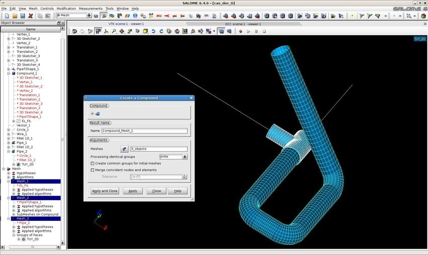
Version 2018
Salome-Meca
Titre : Notice d’utilisation pour la modélisation et le calcul de tuy[...]                        Date : 24/07/2015 Page : 3/18
Responsable : BEIGNION Céline                                                                     Clé : SU1.04.01   Révision                  :
                                                                                                                          8af7ec3e73f3

1          Introduction
           This note describes modeling in Salomé-Meca of lines of pipings made up of the following principal
           elements: right pipes, elbows, t-pieces. The elements of the type bends 3D can be connected simply
           to the intersections of the telegraphic lines.

           A methodological guide is presented in first part. A chapter describes the stages of realization of the
           geometry of the line of pipings, another chapter the stages of realization of the grid.

           One also mentions the main operators Aster to be used for the assignment of the pipes and to carry
           out the connections between elements of different size.

2          Methodology
           One describes in this chapter methodology used to carry out studies of pipings with Salomé-Meca.

           One is pressed in this document on an example of simple modeling (see figure n°1) made up of
           telegraphic elements 1D, elements 2D and elements 3D (t-pieces).

2.1        Geometrical methodology of construction (module GEOM)
           The telegraphic elements 1D are used to describe the network of pipings made up of right elements
           and elbows. To be able to connect the t-piece 3D later on, one modelled the telegraphic lines being
           connected to the t-piece by stopping these telegraphic lines at the points of connections with the t-
           piece.
           The elements 2D are generated starting from a telegraphic section of the line on which one wants
           post-to treat ovalization. Indeed currently the parameters of ovalization of the elements 1D are not
           displayable in Salomé.
           The t-piece with the intersections of the telegraphic lines must be modelled in 3D and with a grid into
           hexahedral (cf paragraph 4.2) to be able to calculate with precision the constraints with the junctions
           pipe principal incidental pipe.
           Currently in Code_Aster, there exist connections 1D/3D and 1D/2D but not 2D/3D. It is thus necessary
           to pass by telegraphic sections at the ends of a t-piece for the connections with elements of the line of
           different size (2D/3D for example).

Warning : The translation process used on this website is a "Machine Translation". It may be imprecise and inaccurate in whole or in part and is
provided as a convenience.
Copyright 2019 EDF R&D - Licensed under the terms of the GNU FDL (http://www.gnu.org/copyleft/fdl.html)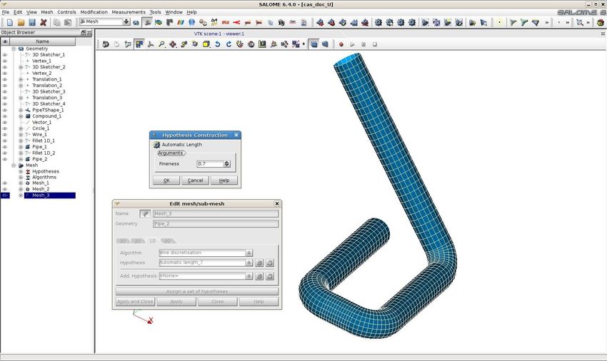
Version 2018
Salome-Meca
Titre : Notice d’utilisation pour la modélisation et le calcul de tuy[...]                        Date : 24/07/2015 Page : 4/18
Responsable : BEIGNION Céline                                                                     Clé : SU1.04.01   Révision                  :
                                                                                                                          8af7ec3e73f3

                            Figure n°1: Network of pipings made up of elements 1D, 2D, 3D

2.2        Preparation of the model for calculation (compound and groups)
           At the end of the realization of the geometry, it is advised to create one compound for each group of
           the same objects dimension composing the line of piping. This object compound will be the support of
           the grid of corresponding dimension. One can then create the geometrical groups necessary to
           calculation on each one of these compound. These geometrical groups will be used to generate the
           groups of corresponding grids automatically.

           Several types of groups of different nature are necessary for calculation:

            •    1D objects:
                 • groups of elements 1D supporting the meshs 1D corresponding to the same characteristic of
                     section.
                 • groups of nodes for each boundary condition to apply at the time of calculation
                 • for modeling pipe, it is necessary to have the group of nodes of departure of each telegraphic
                     section to affect the characteristic GENE_TUYAU.
                 • group of node for each node representing a component additional (pumps, valves,…), for
                     which one will affect modelings DIS_T or DIS_TR.
                 • for each connection of the telegraphic line with an element of different size (connections 1D
                     2D, 1D 3D), a group of node container only one node.

            •    objects 3D:
                 • groups of elements 3D (t-pieces 3D for example).

            •    2D objects:
                 • groups of faces 2D (faces of t-pieces 3D for example for the connections 1D 3D). For this
                     kind of connection, one needs a group of node container only one node for the 1D part and a
                     group of face for the part 3D. That will make it possible to affect the keyword “ 3D_TUYAU ”
                     and possibly the option AXE_POUTRE.
                 • groups of faces supporting the pipe sections 2D corresponding to the same characteristic of
                     section.

2.3        Methodology of construction of the grid (Smesh module)

Warning : The translation process used on this website is a "Machine Translation". It may be imprecise and inaccurate in whole or in part and is
provided as a convenience.
Copyright 2019 EDF R&D - Licensed under the terms of the GNU FDL (http://www.gnu.org/copyleft/fdl.html)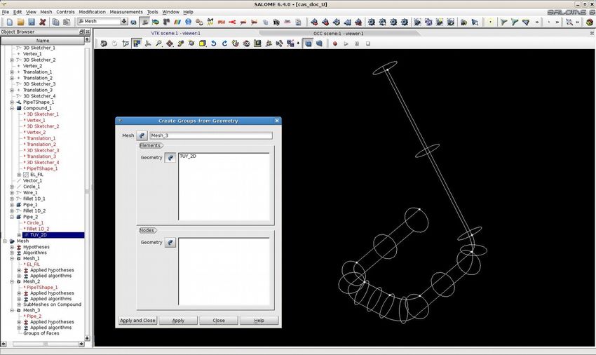
Version 2018
Salome-Meca
Titre : Notice d’utilisation pour la modélisation et le calcul de tuy[...]                        Date : 24/07/2015 Page : 5/18
Responsable : BEIGNION Céline                                                                     Clé : SU1.04.01   Révision                  :
                                                                                                                          8af7ec3e73f3

           The method advised to carry out the grid consists in independently netting each object of the same
           dimension (1D, 2D or 3D) gathered in different the compound geometrical, then to previously generate
           for each grid carried out the groups of meshs starting from the geometrical groups created in module
           GEOM, and finally to create a compound of grid gathering the various grids. This compound of grids
           represents the output datum to be exported with format MED to carry out calculation.

2.4        Code_Aster main operators for calculation
           The Code_Aster main operators to be used for the assignment of the pipes and for the connections
           between elements of different size are:

                •     The operator MODI_MAILLAGE [U4.23.04] OPTION ORIE_NORM_COQUE is necessary in order
                      to direct in the same direction all the normals of the elements 2D.

                •     The operator CREA_MAILLAGE [U4.23.02] OPTION=' QUAD8_9' allows to transform the
                      quadratic elements hull 2D with 8 nodes (QUAD8) into quadratic elements with 9 nodes
                      (QUAD9). This transformation is necessary to be able to use elements COQUE_3D.

                •     Each distinct telegraphic line must be the object of an assignment of the orientations of the
                      main axes of the cross sections elements beam. It is necessary to inform the fields of
                      directions relating to the option GENE_TUYAU (operator AFFE_CARA_ELEM [U4.42.01]), which
                      must be applied to the first node of each telegraphic line (a group of node for each telegraphic
                      line requires).

                •     Use of the discrete elements DIS_TR (to take account mass and the inertia of specific
                      elements representing of the additional components on the line like valves, valves for
                      example), as well as discrete elements DIS_T (to take account only specific mass of certain
                      additional components): the creation of groups of nodes is necessary to be able to apply these
                      elements DIS_TR or DIS_T (operator AFFE_MODELE [U4.41.01]).

                •     Assignment of the telegraphic elements constituting piping in elements pipes TUYAU_3M
                      (rights) or TUYAU_6M (curves), (operator AFFE_MODELE [U4.41.01]). These elements
                      combine at the same time a kinematics of beam, which describes the overall movement of the
                      line of piping, and a kinematics of hull, which brings the description of swelling, the ovalization
                      and the warping of the cross section.

                •     Each change of characteristics of the elements of the line of piping (diameter, thickness,
                      material, etc….), the creation of distinct groups requires (operator AFFE_CARA_ELEM
                      [U4.42.01]).

                •     Modeling of the connections 3D-1D and 2D-1D (operator AFFE_CHAR_MECA option
                      LIAISON_ELEM [U4.44.01]):

                       •    3D-1D (elements pipes): OPTION 3D_TUYAU

                       •    3D-1D (elements beam): OPTION 3D_POU

                       •    2D-1D (elements pipes): OPTION COQ_TUYAU

                       •    2D-1D (elements beam): OPTION COQ_POU

Warning : The translation process used on this website is a "Machine Translation". It may be imprecise and inaccurate in whole or in part and is
provided as a convenience.
Copyright 2019 EDF R&D - Licensed under the terms of the GNU FDL (http://www.gnu.org/copyleft/fdl.html)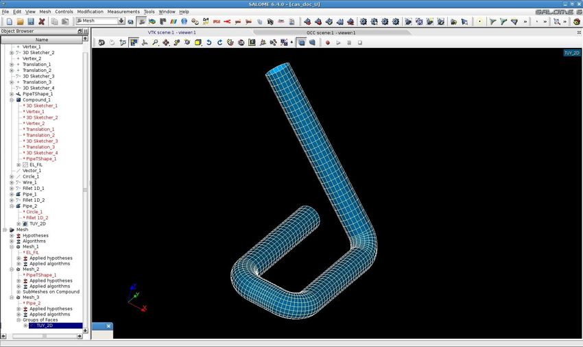
Version 2018
Salome-Meca
Titre : Notice d’utilisation pour la modélisation et le calcul de tuy[...]                        Date : 24/07/2015 Page : 6/18
Responsable : BEIGNION Céline                                                                     Clé : SU1.04.01   Révision                  :
                                                                                                                          8af7ec3e73f3

3          Stages of realization of the geometry
3.1        Telegraphic geometry
           To generate a telegraphic line of piping, one carries out initially the line in the form of right pipes
           successive (see figure n°2), then the elbows are created (see figure n°3).
           The procedure to carry out these operations is detailed in chapters 3.1.1 to 3.1.3.

     Figure n°2: Telegraphic line with right pipes                        Figure n°3: Telegraphic line after addition of the
                                                                                              elbows

3.1.1      Creation of a telegraphic line with the sketcher 3D
           All the geometrical operations must be realized with module GEOM of Salomé-Meca. To launch the
           sketcher 3D while clicking on New entity then on 3D sketch.

           To create a point representing the beginning of the line by seizing the coordinates                         X , Y , Z this point
           while leaving notched Absolute (see figure n°4).
           To click on Apply.

Warning : The translation process used on this website is a "Machine Translation". It may be imprecise and inaccurate in whole or in part and is
provided as a convenience.
Copyright 2019 EDF R&D - Licensed under the terms of the GNU FDL (http://www.gnu.org/copyleft/fdl.html)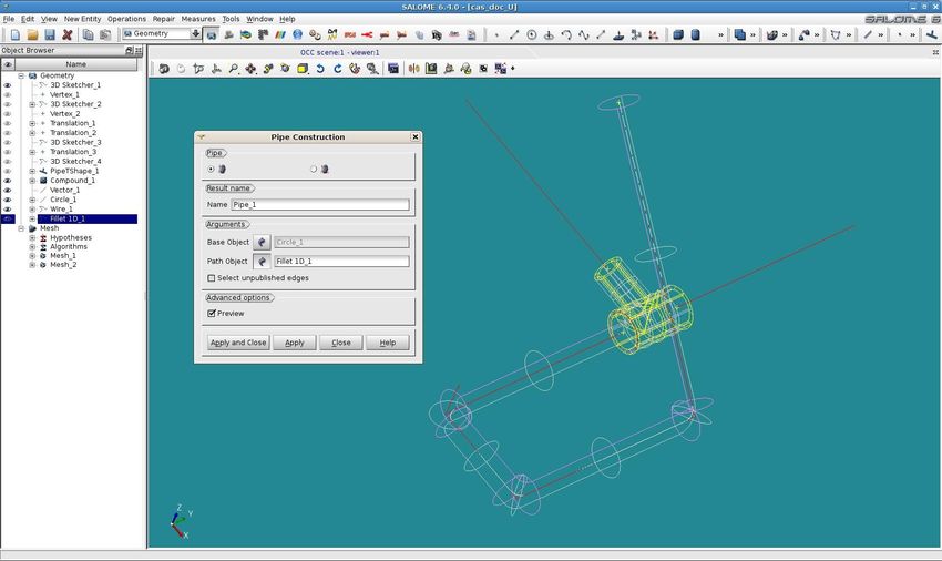
Version 2018
Salome-Meca
Titre : Notice d’utilisation pour la modélisation et le calcul de tuy[...]                        Date : 24/07/2015 Page : 7/18
Responsable : BEIGNION Céline                                                                     Clé : SU1.04.01   Révision                  :
                                                                                                                          8af7ec3e73f3

                              Figure n°4: Creation of the first point of the telegraphic line

           To click on Relative to continue the telegraphic line.
           To seize the coordinates X , Y , Z corresponding at the end of the first right section: length of the first
           section right plus length of the radius of curvature of the first elbow (to see figure n° 5).
           To click on Apply.

                             Figure n°5: Creation of the first section of the telegraphic line

           To repeat this operation for n following sections.
           To click on Sketch Validation to validate the telegraphic sketch carried out.
           One then obtains the telegraphic line in the form of a succession of right sections.

3.1.2      Creation of a telegraphic line with the sketcher 2D
           There exists a sketcher 2D complementary to the sketcher 3D which makes it possible to carry out the
           same operations in a plan, but which comprises besides the options of modeling interesting for the
           user:

Warning : The translation process used on this website is a "Machine Translation". It may be imprecise and inaccurate in whole or in part and is
provided as a convenience.
Copyright 2019 EDF R&D - Licensed under the terms of the GNU FDL (http://www.gnu.org/copyleft/fdl.html)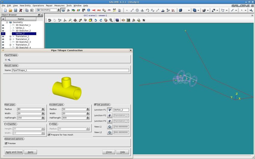
Version 2018
Salome-Meca
Titre : Notice d’utilisation pour la modélisation et le calcul de tuy[...]                        Date : 24/07/2015 Page : 8/18
Responsable : BEIGNION Céline                                                                     Clé : SU1.04.01   Révision                  :
                                                                                                                          8af7ec3e73f3

           These options make it possible to create consecutive sections of line of pipings by directly specifying
           the angle which connects each section of piping and not only the seizure of the coordinates X , Y , Z
           of each section (see figures n°6 and 7).

           In our example one creates a starting point with the option Absolute while clicking on the end of the
           section to which one wants to add the new right elements (see figure n° 6),

                                                                     Starting point

               Figure n°6: Creation of starting point of the telegraphic line with the sketcher 2D

           then it is necessary to click on Direction so that the option Angle appears (as well as the options
           Perpendicular, Tangent, VX-VY). It is necessary to seize the angle desired compared to the
           preceding section as well as the length of the new section (see figure n° 7), to click on apply and to
           create the following right elements by repeating this operation. To validate the telegraphic sketch thus
           created while clicking on Closure sketch.

                                   Figure n°7: Creation of sections with the sketcher 2D

3.1.3      Creation of the elbows on the telegraphic line
           On the formed telegraphic line of a succession of right sections, one now will introduce the elbows.
           To click on Operations Net 1D

Warning : The translation process used on this website is a "Machine Translation". It may be imprecise and inaccurate in whole or in part and is
provided as a convenience.
Copyright 2019 EDF R&D - Licensed under the terms of the GNU FDL (http://www.gnu.org/copyleft/fdl.html)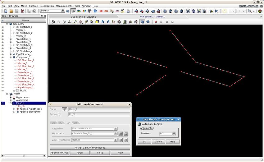
Version 2018
Salome-Meca
Titre : Notice d’utilisation pour la modélisation et le calcul de tuy[...]                        Date : 24/07/2015 Page : 9/18
Responsable : BEIGNION Céline                                                                     Clé : SU1.04.01   Révision                  :
                                                                                                                          8af7ec3e73f3

                                       Figure n°8: Creation of the telegraphic elbows

           To select the telegraphic line in Wire with Edges Double diffusion .
           To select in Vertexes points of connections of the right sections where one wants to create elbows (if
           nothing is selected, by default all connections are taken into account).
           To seize the radius of curvature of the elbows in Radius.
           Prévisualiser the result while clicking on Preview.
           To validate while clicking on Apply or Closed Apply and.

3.2        Creation of a t-piece 3D to be connected on a telegraphic line

           To click in the menu New Entity Primitives Tshape pipe (see figure n°9).

Warning : The translation process used on this website is a "Machine Translation". It may be imprecise and inaccurate in whole or in part and is
provided as a convenience.
Copyright 2019 EDF R&D - Licensed under the terms of the GNU FDL (http://www.gnu.org/copyleft/fdl.html)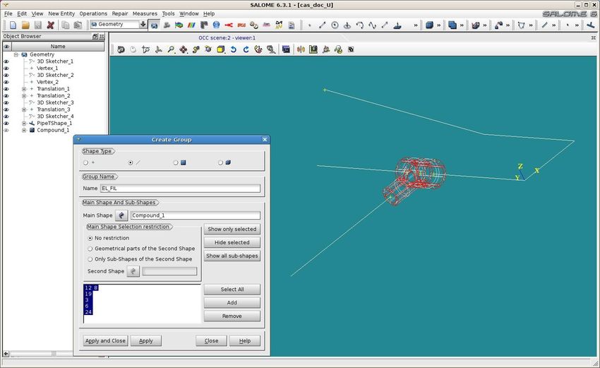
Version 2018
Salome-Meca
Titre : Notice d’utilisation pour la modélisation et le calcul de tuy[...]                        Date : 24/07/2015 Page : 10/18
Responsable : BEIGNION Céline                                                                     Clé : SU1.04.01   Révision                  :
                                                                                                                          8af7ec3e73f3

                                                                                             P2

                                                                                           P3                 P1

                                        Figure n°9: Creation of the positioned t-piece

           To seize geometrical dimensions of the t-piece, to click on set position then to click on the three
           points of connection P1 P2 P3 (Cf appears n°9). To refer to online help for the order of the
           points.

           Note:
           • The lengths of the principal pipe and the incidental pipe must correspond to the lengths between
               the three points of connection of the telegraphic line, if not the lengths appear in red in the dialog
               box of the t-piece and this one cannot be created.
           • The option should be left Prepare for hex mesh notched, to be able to generate thereafter a
               hexahedral grid of the t-piece.

           To validate while clicking on Apply or Closed Apply and.

           Additional options: possibility of creation of a chamfer (Chamfer) or of a leave (Net)

3.3        Creation of a pipe 2D starting from a telegraphic line

           One can apply the following procedure to reach that point:
           • To create a circle of a diameter corresponding to the diameter of neutral fibre of the pipe. For that,
              in the manufacturer of circle, one starts from a point end of the telegraphic line (Center
              arguments Not and to click on the point). To select like parameter Vector the vector colinéaire
              with the first section of the line ( Y in our example n°10 appears). To make Closed Apply and.

Warning : The translation process used on this website is a "Machine Translation". It may be imprecise and inaccurate in whole or in part and is
provided as a convenience.
Copyright 2019 EDF R&D - Licensed under the terms of the GNU FDL (http://www.gnu.org/copyleft/fdl.html)
Version 2018
Salome-Meca
Titre : Notice d’utilisation pour la modélisation et le calcul de tuy[...] Date : 24/07/2015 Page : 11/18
Responsable : BEIGNION Céline Clé : SU1.04.01 Révision :
8af7ec3e73f3
Not origin
Vector
colinéaire
Figure n°10: Creation of the circle before extrusion
• To build the way whereby one wishes to extrude the circle by creating a telegraphic line. For that one
will refer to paragraphs §3.1.1, §3.1.2 and §3.1.3.
• To create the pipe 2D by extrusion (button New Entity Generation Extrusion Along Path)
then selection of the circle for the basic object and selection of the telegraphic line for the way (see
figure n°11). One can prévisualiser the result while clicking on Preview. One validates with Closed
Apply and.
Warning : The translation process used on this website is a "Machine Translation". It may be imprecise and inaccurate in whole or in part and is
provided as a convenience.
Copyright 2019 EDF R&D - Licensed under the terms of the GNU FDL (http://www.gnu.org/copyleft/fdl.html)Version 2018
Salome-Meca
Titre : Notice d’utilisation pour la modélisation et le calcul de tuy[...] Date : 24/07/2015 Page : 12/18
Responsable : BEIGNION Céline Clé : SU1.04.01 Révision :
8af7ec3e73f3
Figure n°11: Extrusion and generation of the pipe 2D
3.4 Geometrical assembly
3.4.1 Creation of a compound of the geometrical objects of the line of piping.
Before creating the groups for calculation, It is necessary to create a compound for each group of the
same objects dimension (1D, 2D or 3D) composing the line of piping.
It is with this intention necessary to click on New Entity Build Compound then to select all the
objects of the same dimension in the tree of construction then to click on Apply or Closed Apply
and. To repeat the operation for the objects of different size.
3.4.2 Creation of the geometrical groups
One must create the geometrical groups desired on each one of the compound previously created.
These geometrical groups will be used to generate the groups of corresponding grids automatically.
The creation of these groups is carried out by using the function New entity Group Create, by
selecting the compound in Shape hand, then by selecting the objects graphically then to click on
Add. To put the name of group desired in Name then to click on Apply or Closed Apply and.
One creates for example a group including all the elements telegraphic of the line ( EL_FIL in our
example, to see figure n°12).
Warning : The translation process used on this website is a "Machine Translation". It may be imprecise and inaccurate in whole or in part and is
provided as a convenience.
Copyright 2019 EDF R&D - Licensed under the terms of the GNU FDL (http://www.gnu.org/copyleft/fdl.html)Version 2018
Salome-Meca
Titre : Notice d’utilisation pour la modélisation et le calcul de tuy[...] Date : 24/07/2015 Page : 13/18
Responsable : BEIGNION Céline Clé : SU1.04.01 Révision :
8af7ec3e73f3
Figure n°12: Creation of the geometrical groups
Warning : The translation process used on this website is a "Machine Translation". It may be imprecise and inaccurate in whole or in part and is
provided as a convenience.
Copyright 2019 EDF R&D - Licensed under the terms of the GNU FDL (http://www.gnu.org/copyleft/fdl.html)Version 2018
Salome-Meca
Titre : Notice d’utilisation pour la modélisation et le calcul de tuy[...] Date : 24/07/2015 Page : 14/18
Responsable : BEIGNION Céline Clé : SU1.04.01 Révision :
8af7ec3e73f3
4 Stages of realization of the grid
To carry out the grid of the network of pipings, it is necessary to activate module SMESH of Salomé-
Meca.
4.1 Grid of a telegraphic line
To create a new grid: Mesh Create Mesh while taking as parameter geometry the group of
telegraphic elements created in the compound géométrique1D (EL_FIL in our example) with like
advised parameters:
• Algorithm = wire discretization and
• Hypothesis = Automatic Length
• (in our example Fineness=0,2 to see figure n°13).
Figure n°13: Grid of a telegraphic line
4.2 Hexahedral grid of the elements t-pieces 3D
One can create a hexahedral grid of the t-pieces 3D in the following way:
• To create a new grid: Mesh Create Mesh while taking as parameter geometry a group of
elements 3D created in the geometrical compound 3D (PipeTShape_1 in our example).
• To select Hexahedron (I, J, K) like algorithm 3D
• To select Quadrangle (Mapping) like algorithm 2D
• To select Wire discretization Hypothesis Nb. Segments_1 like algorithm 1D (by
putting 10 for Number of segments for example)
• to make OK then Closed Apply and.
• To make right click on Mesh_X thus created in the tree of construction then compute.
Warning : The translation process used on this website is a "Machine Translation". It may be imprecise and inaccurate in whole or in part and is
provided as a convenience.
Copyright 2019 EDF R&D - Licensed under the terms of the GNU FDL (http://www.gnu.org/copyleft/fdl.html)Version 2018
Salome-Meca
Titre : Notice d’utilisation pour la modélisation et le calcul de tuy[...] Date : 24/07/2015 Page : 15/18
Responsable : BEIGNION Céline Clé : SU1.04.01 Révision :
8af7ec3e73f3
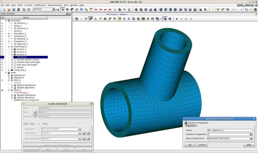
If one wants to modify the discretization of the grid in the thickness of the pipes for example, it is
necessary to create under grid while clicking on Mesh Create Sub-Mesh :
• To select like parameter Mesh complete grid Mesh2,
• like parameter Geometry the group Thickness of PipeTShape_1 in the tree of Geometry,
• then like parameters 1D:
• Algorithm Wire Hypothesis discretization
• Nb. Segments (Number of Segments 3 in our example),
• then to click on OK then on Closed Apply and.
• to make right click on Mesh_X thus created in the tree of construction
• then compute .
One obtains the grid represented on the figure n°14 which contains 3 elements in the thickness of the
pipes.
Figure n°14: Hexahedral grid of a t-piece 3D
4.3 Grid of a line 2D
One can create a grid 2D in the following way:
• To click on Mesh Create Mesh,
• to select in the field Geometry the pipe 2D or the compound of pipes 2D created with the
module Geometry,
• to select quadrangle mapping in the mitre 2D field Algorithm
• then in the mitre 1D field Algorithm to select Wire discretization Automatic
Length Fineness ( 0,7 on the example n°15 is reproduced)
Warning : The translation process used on this website is a "Machine Translation". It may be imprecise and inaccurate in whole or in part and is
provided as a convenience.
Copyright 2019 EDF R&D - Licensed under the terms of the GNU FDL (http://www.gnu.org/copyleft/fdl.html)Version 2018
Salome-Meca
Titre : Notice d’utilisation pour la modélisation et le calcul de tuy[...] Date : 24/07/2015 Page : 16/18
Responsable : BEIGNION Céline Clé : SU1.04.01 Révision :
8af7ec3e73f3
Figure n°15: Grid quadrangle of a line 2D
4.4 Assembly of the grid
4.4.1 Creation of the groups of grid
The groups of grid can be generated starting from the geometrical groups created in chapter 2.7 in the
following way:
To click on Mesh then on Create Groups from Geometry :
To select in the field Geometry (Elements or Nodes) the geometrical group selected in the tree of
construction of Geometry.
One can choose to obtain a group of elements (field Geometry elements) or a group of nodes (field
Nodes Geometry), to see figure n°16.
Warning : The translation process used on this website is a "Machine Translation". It may be imprecise and inaccurate in whole or in part and is
provided as a convenience.
Copyright 2019 EDF R&D - Licensed under the terms of the GNU FDL (http://www.gnu.org/copyleft/fdl.html)Version 2018
Salome-Meca
Titre : Notice d’utilisation pour la modélisation et le calcul de tuy[...] Date : 24/07/2015 Page : 17/18
Responsable : BEIGNION Céline Clé : SU1.04.01 Révision :
8af7ec3e73f3
Figure n°16: Choice of the geometrical groups for the creation of a group of meshs
to click on Closed Apply and one obtains the group of elements corresponding to the selected
geometrical group (TUY_2D in our example n°17 appears).
Figure n°17: Group of meshs
Warning : The translation process used on this website is a "Machine Translation". It may be imprecise and inaccurate in whole or in part and is
provided as a convenience.
Copyright 2019 EDF R&D - Licensed under the terms of the GNU FDL (http://www.gnu.org/copyleft/fdl.html)Version 2018
Salome-Meca
Titre : Notice d’utilisation pour la modélisation et le calcul de tuy[...] Date : 24/07/2015 Page : 18/18
Responsable : BEIGNION Céline Clé : SU1.04.01 Révision :
8af7ec3e73f3
4.4.2 Creation of a compound of grids
It is necessary to click on Mesh then on Build Compound :
To select the grids composing the compound in the tree of construction of Mesh (by using the keys
shift or ctrl to select them).
To recover with identical in the compound the existing groups in the grids composing the compound, to
leave Unit like parameter of the field Processing identical groups.
To click on Closed Apply and, one obtains the compound of grids following for our example
appears n°18:
Figure n°18: Creation of a compound of grids
One can export this compound with format MED to be able to carry out a Code_Aster calculation
(File, export, Med slips by).
Warning : The translation process used on this website is a "Machine Translation". It may be imprecise and inaccurate in whole or in part and is
provided as a convenience.
Copyright 2019 EDF R&D - Licensed under the terms of the GNU FDL (http://www.gnu.org/copyleft/fdl.html)You can also read