On the Manipulation of Articulated Objects in Human-Robot Cooperation Scenarios
←
→
Page content transcription
If your browser does not render page correctly, please read the page content below
On the Manipulation of Articulated Objects in
                                                   Human-Robot Cooperation Scenarios

                                          Alessio Capitanelli, Marco Maratea, Fulvio Mastrogiovanni1 , Mauro Vallati
                                         A. Capitanelli, M. Maratea and F. Mastrogiovanni are with the Department of Informatics,
                                         Bioengineering, Robotics and Systems Engineering, University of Genoa, via Opera Pia 13,
                                                                             16145 Genoa, Italy.
arXiv:1801.01757v2 [cs.RO] 13 Jan 2018

                                          M. Vallati is with the School of Computing and Engineering, University of Huddersfield,
                                                           Queensgate, HD13DH, Huddersfield, United Kingdom.

                                         Abstract

                                            Articulated and flexible objects constitute a challenge for robot manipula-
                                         tion tasks, but are present in different real-world settings, including home and
                                         industrial environments. Current approaches to the manipulation of articulated
                                         and flexible objects employ ad hoc strategies to sequence and perform actions
                                         on them depending on a number of physical or geometrical characteristics re-
                                         lated to those objects, as well as on an a priori classification of target object
                                         configurations.
                                            In this paper, we propose an action planning and execution framework, which
                                         (i) considers abstract representations of articulated or flexible objects, (ii) in-
                                         tegrates action planning to reason upon such configurations and to sequence
                                         an appropriate set of actions with the aim of obtaining a target configuration
                                         provided as a goal, and (iii) is able to cooperate with humans to collaboratively
                                         carry out the plan.
                                            On the one hand, we show that a trade-off exists between the way articulated
                                         or flexible objects are perceived and how the system represents them. Such a
                                         trade-off greatly impacts on the complexity of the planning process. On the
                                         other hand, we demonstrate the system’s capabilities in allowing humans to
                                         interrupt robot action execution, and – in general – to contribute to the whole

                                           1 Corresponding   author. Email address: fulvio.mastrogiovanni@unige.it

                                         Preprint submitted to Robotics and Autonomous Systems                  January 16, 2018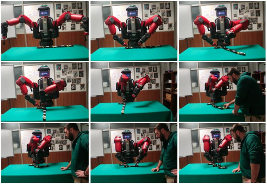
manipulation process.
   Results related to planning performance are discussed, and examples with a
Baxter dual-arm manipulator performing actions collaboratively with humans
are shown.
Keywords:
Planning; Knowledge representation; Software architecture; Articulated object.

1. Introduction

   The introduction of the Industry 4.0 paradigm is expected to redefine the
nature of shop-floor environments along many directions, including the role
played by robots in the manufacturing process [1, 2]. One of the main tenets
considered in Industry 4.0 is the increased customer satisfaction via a high
degree of product personalization and just-in-time delivery. On the one hand, a
higher level of flexibility in manufacturing processes is needed to cope with such
diversified demands, especially in low-automation tasks. On the other hand,
skilful robots working alongside humans can be regarded as a valuable aid to
shop-floor operators, who can supervise robots’ work and intervene when needed
[3], whereas robots can be tasked with difficult or otherwise stressful operations.
   Human-robot cooperation (HRC) processes in shop-floor environments are
a specific form of human-robot interaction (HRI) with at least two important
specificities. The first is related to the fact that the cooperation is targeted
towards a well-defined objective (e.g., an assemblage, a unit test, a cable har-
nessing operation), which must be typically achieved in a short amount of time.
The second has to do with the fact that humans need to feel (at least partially)
in control [4, 5]: although grounded in the cooperation process, their behaviours
could be unpredictable in specific cases, with obvious concerns about their safety
[6, 7]; they may not fully understand robot goals [8]; robot actions may not be
considered appropriate for the peculiar cooperation objectives [9, 5].
   As far as the cooperation process is concerned, two high-level directives must
be taken into account:

                                        2
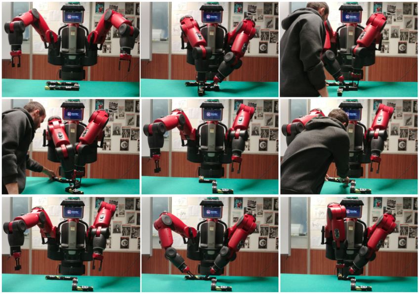
Figure 1: Two examples of a cable harnessing operation.

 D1 cooperation models (and robot action planning techniques) enforcing the
     prescribed objectives must be adopted [10, 11];
 D2 the robot must be flexible enough to adapt to human operator actions
     avoiding a purely reactive approach [12, 13], and to make its intentions
     clear [14, 15].

These two directives lead to three functional requirements for a HRC architec-
ture. The robot must be able to:

 R1 (at least implicitly) recognize the effects of human operator actions [16];
 R2 adapt its behaviour on the basis of two elements: human operator actions
     themselves and the whole cooperation objectives;
 R3 employ planning techniques allowing for a fast action re-planning when
     needed, e.g., when planned actions cannot be executed for sudden changes
     in the environment or inaccurate modelling assumptions [17].

   Among the various tasks typically carried out in the shop-floor, the manip-
ulation of flexible or articulated objects, e.g., cable harnessing operations, is
particularly challenging [18, 19, 20, 21], as can be seen in Figure 1: on the one
hand, it is usually beneficial to accurately plan the expected cable configura-
tions on the harnessing table in advance, thus confirming requirement R3 ; on
the other hand, it is often necessary to keep a cable firm using more than two
grasping points and to re-route the wiring pattern, which – when done collabo-
ratively with a robot, for instance to place bundle retainers or junction fixtures

                                         3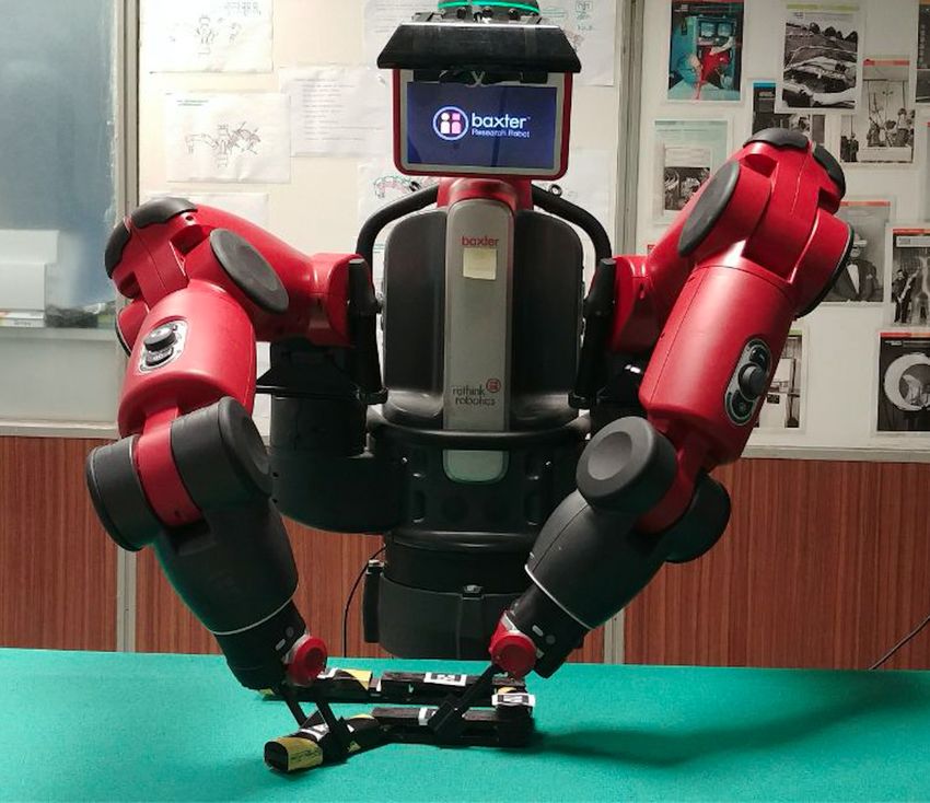
– leads to requirements R1 and R2 above.
   In the literature, the problem of determining the 2D or 3D configuration
of flexible or articulated objects has received much attention in the past few
years [22, 23], whereas the problem of obtaining a target configuration via ma-
nipulation has been explored in motion planning [24, 25, 26]. However, in the
context of HRC, perception and manipulation are only part of the challenges to
address. Conceptually speaking, the outcome of such approaches is a continuous
mapping in 2D or 3D space from an initial to a target object’s configuration
[27, 28, 25, 29], subject to a number of simplifying hypotheses as far as object
models are concerned [30, 31, 32, 33, 34]. This observation leads to two further
functional requirements. The robot must be able to:

 R4 represent object configurations adopting suitable modelling assumptions,
      and then segment the whole manipulation problem in simpler actions
      to appropriately sequencing and monitoring, each action operating in-
      between two intermediate configurations;
 R5 represent the actions to perform using a formalism allowing for plan execu-
      tions that are robust with respect to unexpected events (e.g., the human
      operator suddenly intervenes), and modelling errors (e.g., not modelled
      objects to be removed from the workspace).

   In this paper, we consider articulated objects as suitable models for flexible
objects [24], and we address the following challenges: (i) we provide two repre-
sentation and planning models for the classification of articulated object configu-
rations and the sequencing of manipulation actions, using an OWL-DL ontology-
based formalism and the Planning Domain Definition Language (PDDL) [35],
and we test them using two state-of-the-art PDDL planners, namely Probe [36]
and Madagascar [37], as well as with the VAL plan validator [38]; (ii) we em-
bed such models in a reactive/deliberative architecture for HRC, referred to
as planHRC, which takes human operator behaviours into account and is im-
plemented on top of the ROSPlan [39] and MoveIt! [40] frameworks; and (iii)
we discuss how perception assumptions and representation schemes impact on

                                        4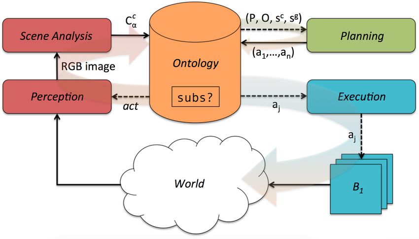
planning and execution in HRC scenarios. The planHRC architecture has
been deployed on a dual-arm Baxter manipulator, which is used in all of our
experiments.
   The paper is organised as follows. Section 2 discusses relevant approaches
for the work described here. Section 2.2 introduces more formally the problem
we address, as well as the scenario we consider. The planHRC’s architec-
ture is described in detail in Section 3, where the overall information flow, the
representation and reasoning challenges, and the planning models are discussed.
Experiments to validate the architecture are described in Section 4. Conclusions
follow.

2. Background

2.1. Planning Techniques in Human-Robot Cooperation

   A number of studies have been conducted to investigate the role and the
acceptability of automated planning techniques in HRC scenarios. As high-
lighted in a field study by Gombolay and colleagues, two factors are important
to maximise human satisfaction in HRC [41]: on the one hand, humans must be
allowed to choose their own tasks freely, i.e., without them being assigned by an
algorithm, subject to the fact that the cooperation is successful; on the other
hand, the overall system’s (i.e., the human-robot team’s) performance must be
at high standards. It is noteworthy that these two factors may conflict in case
of a lazy or not focused human attitude. However, when required to trade-off
between them, humans show a strong preference for system’s performance over
their own freedom. This study well fits with the requirements R1 , R2 and R3
outlined above, and opens up to an idea of a collaborative robot as a device not
only able to aid human workers, but also capable of keeping them in focus and
steering the cooperation towards its objectives if deviations occur.
   As a follow-up of the work discussed in [41], a study about the actual amount
of control a human worker would like to have when collaborating with a robot
has been reported in [42]. The main finding of this study is that human workers

                                       5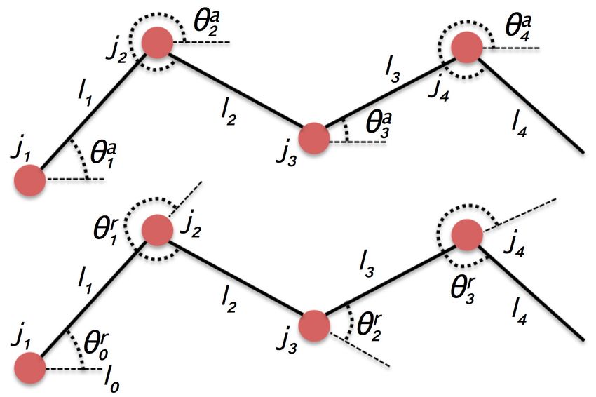
tend not to prefer a total control of the cooperation process, rather they opt for
partial control. This is confirmed by the fact that the overall team’s performance
seems higher when the robot determines what actions must be carried out by
the human. As a consequence, a key factor for the acceptance of collaborative
robots is finding a sensible – yet efficient – trade-off between performance and
human control.
   In order to determine such trade-off, which may depend on the peculiar
emotional or physical status of the human worker, one possibility is to encode
in the planning process her/his preferences as far as tasks and operations are
concerned [43]. In a first series of experiments, the use of human preferences in
the planning algorithm led to an overall decrease in performance, correlated with
human subjective perceptions of robots not in line with the main cooperation
objectives. This suggests that a subjective assessment of the HRC process tends
to attribute major inefficiencies to robots, and confirms that this is a crucial
aspect for the applicability of collaborative robots in industrial scenarios.
   Techniques for HRC available in the literature target these issues only to
a partial extent, positioning themselves at different levels in the trade-off scale
outline above. It is possible to identify two relevant trends for our work.
   Approaches in the first class aim at defining cooperation models, i.e., data
structures modelling the task to be jointly carried out, while keeping flexibility
and human preferences into account [44, 45, 3, 10, 15, 46, 11].
   A probabilistic planner is used in [44] to sequence already defined partial
plans, which include preferences about human preferred actions. Once deter-
mined, the sequence of partial plans cannot be changed, therefore no flexibility
for the human is allowed. Such a limitation is partially overcome by the ap-
proach described in [45], where an algorithm to adapt on-line both the action
sequence and a number of action parameters is described. This is achieved us-
ing a temporal formulation making use of preferences among actions, and using
optimization techniques to identify the sequence best coping with preferences
and constraints. Still, the algorithm weighs more plan optimality (in terms of a
reduced number of actions, or the time to complete the plan), and uses human

                                        6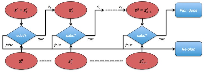
preferences as soft constraints. The approach by Tsarouchi and colleagues [3]
assumes that a human and a robot co-worker operate in different workspaces.
The focus is on allocating tasks to the human or the robot depending on their
preferences, suitability and availability, and the cooperation model is repre-
sented using an AND/OR graph. Although human preferences are taken into
account, task allocation is a priori fixed and cannot be changed at run-time. A
similar approach is considered in [10], where the assumption about the separate
workspaces is relaxed. Hierarchical Task Models (HTMs) are used in [15], where
the robot is given control on task allocation and execution is modelled using Par-
tially Observable Markov Decision Processes (POMDPs). However, the focus of
this approach is on robot communication actions to enhance trust in the human
counterpart and to share a mutual understanding about the cooperation objec-
tives. A similar approach is adopted in [46], where HTMs are substituted by
Hierarchical Agent-based Task Planners (HATPs) and POMDPs are replaced
by Petri Network Plans (PNPs). However, differently from the approach in
[15], the work by Sebastiani and colleagues support on-line changes during plan
execution. Finally, the work by Darvish and colleagues represents cooperation
models using AND/OR graphs, and allows for a switch among different coop-
eration sequences at runtime [11], therefore allowing humans to redefine the
sequence of tasks among a predefined set of choices. The human does not have
to explicitly signal the switch to the robot, whereas the robot adapts to the new
cooperation context reactively.
   The second class includes techniques focused on understanding, anticipating
or learning human behaviours on-line [47, 48, 49, 50, 51, 52].
   The work by Agostini and colleagues adopts classical planning approaches to
determine an appropriate sequence of actions, given a model of the cooperation
defined as a domain and a specific problem to solve [47]. At runtime, the system
ranks a predefined series of cause-effect events, e.g., observing their frequency as
outcomes of human activities, and updates the cooperation model accordingly.
Markov Decision Processes (MDPs) are used in [48] to model the cooperation.
In particular, the human and the robot are part of a Markov decision game,

                                         7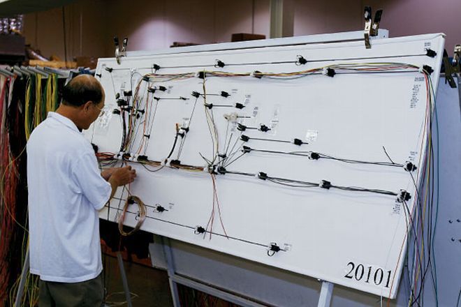
and must cooperatively conclude the game, i.e., carrying out the cooperation
process. Human actions are detected on-line, which influences robot’s behaviour
at run-time. A similar approach, which takes into account temporal constraints
among tasks, is discussed in [49]. Statistical techniques to recognize human
actions and to adapt an already available plan accordingly are presented in
[50]. Human deviations from the plan are detected. When this happens, re-
planning (including task allocation) occurs to achieve the cooperation objectives.
While the approaches discussed so far are quite conservative as far as robot’s
autonomy in the cooperation process is concerned, the work discussed in [51]
exploits Bayesian networks to predict the occurrence and the timing of human
actions. Such a prediction is used to perform preparatory actions before an
event even occurs. While the overall system’s performance is greatly improved,
humans tend to be confused by the seemingly anticipative robot’s behaviour.
Hierarchical Task Networks (HTNs) are used in [52] to embed communication
actions in the cooperation process. When specific deviations from the plan are
detected, such communication actions enforce the adherence to the plan.

2.2. Rationale, Assumptions, Problem Statement, Reference Scenario

   planHRC takes inspiration from the findings in [41, 42, 43] to devise a
cooperation model with the following characteristics:

   • similarly to the work in [47], the robot plans an appropriate, optimal,
     sequence of actions to determine relevant intermediate configurations for
     an articulated object (considered as a simplified model for a flexible object
     like a cable), in order to determine a final target configuration, therefore
     coping with requirement R4 ;

   • during plan execution, the robot always monitors the outcome of each
     action, and compares it with the target configuration to achieve, therefore
     limiting the burden on the human side [42];

   • normally, the human can supervise robot actions: when a robot action is
     not successful, or a plan cannot be found, the human can intervene on the

                                        8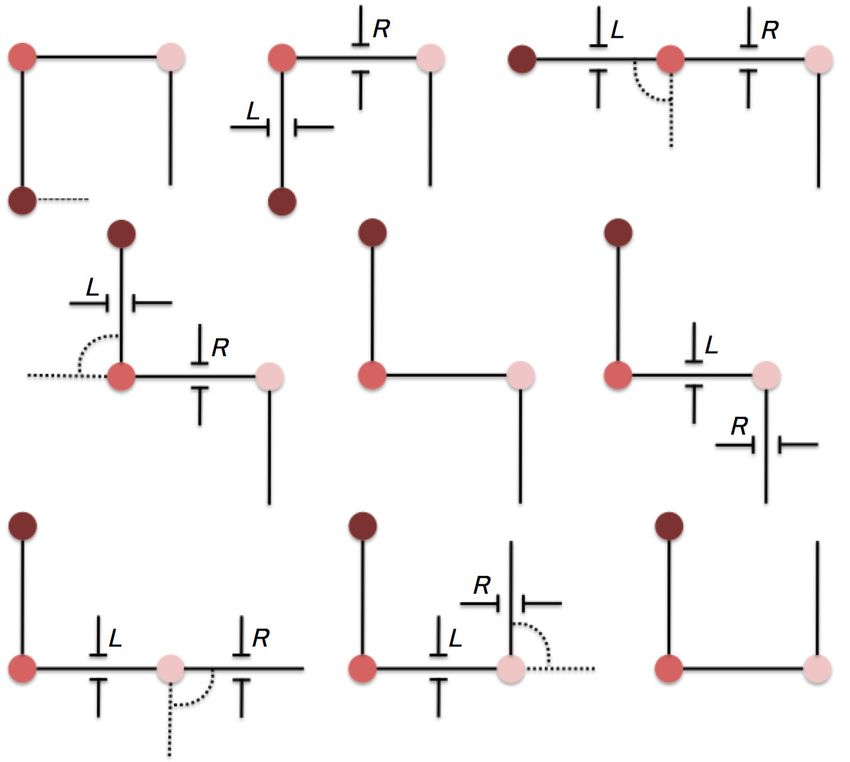
robot’s behalf performing her/his preferred action sequence [43], therefore
     meeting R1 and R2 ;

   • at any time, the human can intervene (e.g., performing an action the
     robot was tasked with, or changing the articulated object’s configuration),
     and the robot adapts to the new situation, in accordance with [43] and
     requirements R3 and R5 .

   More specifically, the problem we consider in this paper is three-fold: (i)
given a target object’s configuration, determining a plan as an ordered set of
actions:
                           a = {a1 , . . . , ai , . . . , aN ; ≺},             (1)

where each action ai involves one or more manipulation operations to be exe-
cuted by a dual-arm robot, (ii) designing a planning and execution architecture
for the manipulation of articulated objects, which is efficient and flexible in
terms of perceptual features, their representation and action planning, and (iii)
seamlessly integrating human actions in the loop, allowing the robot to adapt
to novel, not planned beforehand, object’s configurations online.
   In order to provide planHRC with such a features, we pose a number of
assumptions described as follows:

 A1 flexible objects are modelled as articulated objects with a number of links
     and joints, as it is customary also for computational reasons [24]; we as-
     sume an inertial behaviour, i.e., rotating one link causes the movement of
     all upstream or downstream links, depending on the rotation joint; while
     this assumptions may not hold for soft flexible objects, it may reasonably
     hold for a wide range of bendable cables or objects;

 A2 the effects of gravity on the articulated object’s configurations are not
     considered, and the object is located on a table during all operations;

 A3 we do not assume in this paper any specific grasping or manipulation
     strategies to obtain a target object’s configuration starting from another

                                             9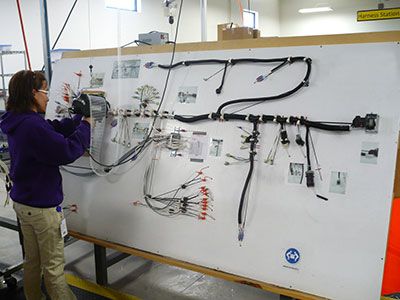
configuration; however, we do consider when an action ai cannot be com-
      pleted because of unexpected events or modelling omissions;

  A4 perception of articulated objects is affected by noise, but the symbol
      grounding problem, i.e., the association between perceptual features and
      the corresponding symbols in the robot’s knowledge representation system
      [53], is assumed to be known.

    On the basis of assumption A1 , we focus on articulated objects only. As
anticipated above, we need to represent object’s configurations. We define an
articulated object as a 2-ple α = (L, J ), where L is the ordered set of its
|L| links, i.e., L = {l1 , . . . , lj , . . . , l|L| ; ≺}, and J is the ordered set of its |J|
joints, i.e., J = {j1 , . . . , jj , . . . , j|J| ; ≺}. Each link lj ∈ L is characterized by
two parameters, namely a length λl and an orientation θl . We allow only for
a limited number of possible orientation values. This induces an ordered set
O of |O| allowed orientation values, i.e., O = {o1 , . . . , o|O| ; ≺}, such that an
orientation θl can assume values in O. We observe that in a cable harnessing
operation this is only a minor simplification, since operators tend to distribute
cables along predefined directions. Given a link lj , we define two sets, namely
up(lj ) and down(lj ), such that the former is made of upstream links, i.e., from
l1 to lj−1 , whereas the latter includes downstream links from lj+1 to l|J| .
    Orientations can be expressed with respect to an absolute, possibly robot-
centred reference frame, or – less intuitively – relative to each other, for instance
θli can represent the rotation with respect to θli−1 . At a first glance, the ab-
solute representation seems preferable because it leads to the direct perception
of links and their orientations with respect to a robot-centred reference frame,
whereas the set of absolute orientations constitute the overall object’s config-
uration. When a sequence of manipulation actions are planned, changing one
absolute orientation requires – in principle – the propagation of such change
upstream or downstream the object via joint connections, which (hypothesis
H1 ) is expected to increase the computational burden on the reasoner and (H2 )
may lead to suboptimal or redundant action sequences, because the propagation

                                             10
Figure 2: Two possible representations: absolute (top) and relative (bottom).
may jeopardise the effects of previous actions in the plan, or to sequences which
cannot be fully understood by the human. On the contrary, the less intuitive
relative approach assumes the direct perception of the relative orientations be-
tween pairwise links, and thus the overall object’s configuration is made up of
incremental rotations. In this case, (H3 ) computation is expected to be less
demanding, since there is no need to propagate one change in orientation to up-
stream or downstream links, and therefore (H4 ) actions on different links tend
to be planned sequentially. This has obvious advantages since it leads to shorter
plans (on average), which could be further shortened by combining together ac-
tion sub-sequences (e.g., two subsequent reorientations of 45 deg consolidated
as one 90 deg single action), and to easy-to-understand plans.
If the object is represented using absolute orientations (Figure 2 on the top),
then its configuration is a |L|-ple:
Cα,absolute = θ1a , . . . , θla , . . . , θ|L|
a
, (2)
where it is intended that the generic element θla is expressed with respect to an
absolute reference frame. Otherwise, if relative angles are used (Figure 2 on the
bottom), then the configuration must be augmented with an initial virtual link
l0 in order to define a reference frame, and therefore:
r
Cα,relative = θ0,virtual , θ1r , . . . , θlr , . . . , θ|L|
r
. (3)
11Figure 3: The experimental scenario: a Baxter dual-arm manipulator operating on an artic-
ulated object.
In principle, while the relative representation could model an object’s configu-
ration with one joint less compared to the absolute representation, the resulting
configuration would not be unique (indeed there were infinitely many), since
the object would maintain pairwise relative orientations between its links even
when rotated as a whole. Therefore, an initial virtual reference link is added to
the chain.
In order to comply with assumption A2 , we set up an experimental scenario
where a Baxter dual-arm manipulator operates on articulated objects located
on a table in front of it (Figure 3). Rotation operations occur only around axes
centred on the object’s joints and perpendicular to the table where the object is
located. We have crafted a wooden articulated object made up of |L| = 5 15.5
cm long links, connected by |J| = 4 joints. Links are 3 cm thick. The object
can be easily manipulated by the Baxter’s standard grippers, which complies
with assumption A3 . To this aim, we adopt the MoveIt! framework. The
Baxter is equipped with an RGB-D device located on top of its head pointing
downward to the table. Only RGB information is used. QR tags are fixed to
12Figure 4: The information flow in planHRC.
each object’s link, which is aimed at meeting assumption A4 . Each QR code
provides a 6D link pose, which directly maps to an absolute link orientation θla .
Finally, if relative orientations are employed, we compute them by performing
an algebraic sum between the two absolute poses of two consequent links, e.g.,
θ1r = |θ2a − θ1a |. A human can supervise robot operations and intervene when
necessary from the other side of the table.
3. planHRC’s Architecture
3.1. Information Flow
planHRC allows for interleaved sensing, planning, execution and coopera-
tion with a human using a number of parallel loops orchestrating the behaviour
of different modules (Figure 4). Assuming that an articulated object α is lo-
cated on the table in front of the robot, we want to modify its current config-
uration ccα to obtain a goal configuration cgα , which can be expressed as (2) or
(3), i.e., it holds that Cα,absolute (ccα ) and Cα,absolute (cgα ), or Cα,relative (ccα ) and
Cα,relative (cgα ), respectively.
The goal configuration cgα is encoded as assertional knowledge in an OWL-
based Ontology module [54]. When this happens, the Perception module is
activated, and the Baxter’s camera acquires an image of the workspace. It is
13noteworthy that the Perception module acquires images continuously, but for
the sake of simplicity we treat each acquisition as if it were synchronous with
action execution. The acquired image is filtered and registered, and appropri-
ate artefact removal procedures are applied to produce an image suitable for
feature extraction, which is fed to the Scene Analysis module. A perceived
configuration cpα (i.e., the current configuration ccα ) is extracted from the im-
age, and a representation of it stored in the Ontology module. Both ccα and cgα
are represented using conjunctions of class instances, which model such predi-
cates as Connected, to indicate whether two links are connected by a joint, or
HasOrientation, to define angle orientations. If ccα and cgα are not compatible then
a planning process occurs. In order to determine compatibility, we assume the
presence of an operator D that, given a terminological or assertional element
in the ontology, returns its description in OWL formalism. Therefore, if the
description of ccα is not subsumed by the description of cgα , i.e., it does not hold
that D(ccα ) v D(cgα ), the planner is invoked. Specifically, a Planner module is
activated, which requires the definition of relevant predicates P1 , . . . , P|P | , and
possible action types A1 , . . . , Aj , . . . , A|A| in the form:
Aj = pre(Aj ), ef f − (Aj ), ef f + (Aj ) ,
(4)
where pre(Aj ) is the set of preconditions (in the form of predicates) for the
action to be executable, ef f − (Aj ) is the set of negative effects, i.e., predicates
becoming false after action execution and ef f + (Aj ) is the set of positive effects,
i.e., predicates becoming true after execution. For certain domains, it is useful
to extend (4) to allow for additional positive or negative effects, i.e., predicates
becoming true or false in case certain additional conditions hold. A conditional
action can be modelled as:
Aj = pre(Aj ), ef f − (Aj ), ef f + (Aj ), prea (Aj ), ef fa− (Aj ), ef fa+ (Aj ) ,
(5)
where pre(Aj ), ef f − (Aj ) and ef f + (Aj ) are defined as before, prea (Aj ) is
the set of additional preconditions, whereas and ef fa− (Aj ) and ef fa+ (Aj ) are
the sets of additional effects subject to the validity of predicates in prea (Aj ).
14Figure 5: The planning and execution pipeline.
Furthermore, the Planner requires a suitable description of the current state sc
(including a description of ccα ) and the goal state sg (including cgα ), described
using an appropriate set of ground predicates p1 , . . . , p|p| . This information,
encoded partly in the terminological section and partly in the assertional section
of the Ontology module, is translated in a format the Planner module can use,
namely the Planning Domain Definition Language (PDDL) [55].
A plan, as formally described in (1), is an ordered sequence of N actions
whose execution changes the current state from sc to sg through a set of inter-
mediate states. In a plan, each action may correspond to one or more scripted
robot behaviours. For example, rotating a link lj+1 may require the robot to
(i) keep the upstream link lj steady with its left gripper, and (ii) rotate lj+1 of
a certain amount with the right gripper. Such sequence shall not be encoded
in the planning process, thereby reducing planning cost, but demanded to an
action execution module. If a plan is found, each action is encoded in the Ontol-
ogy, along with all the expected intermediate states sc = se1 , se2 , . . . , sg = seN +1 ,
which result from actions. The Execution module executes action by action ac-
tivating the proper modules in the architecture, e.g., such behaviours as motion
planning, motion execution, obstacle avoidance or grasping.
Each action aj in a plan is assumed to transform a state sej into a state sej+1 ,
such that:
sej+1 = sej \ ef f − (aj ) ∪ ef f + (aj ).
(6)
15If aj has additional conditions, then (6) is modified as:
sej+1 = sej \ ef f − (aj ) ∪ C − (prea (aj )) ∪ ef f + (aj ) ∪ C + (prea (aj )) , (7)
where conditions C − and C + return the sets ef f − +
a (aj ) and ef f a (aj ), respec-
tively, if the conditions in prea (aj ) hold, and ∅ otherwise. Before the action
is executed, the Ontology module activates Perception to acquire a new image.
Again, this induces a new perceived, current configuration ccα . Every time this
happens, two situations can happen: if ccα corresponds to a current perceived
state sc whose description is subsumed by the description of a state sej−1 possibly
generated applying an action aj−1 or as a consequence of human intervention,
i.e., D(sc ) v D(sej−1 ), then the execution continues with action aj until a state is
reached which is subsumed by D(sg ); otherwise, a new planning process occurs,
considering the current state sc as a new initial state and keeping the previous
goal state sg .
A few remarks can be made. When an action aj is executed, the expected
intermediate state sej is treated as a set of normative ground predicates, i.e., it
defines the normal, expected state for aj to be feasible. Whether sej is obtained
as a result of a previous action, or with the help of the human operator is not
relevant for aj . On the contrary, deviations from it are treated as violations
and therefore the system tries to re-plan in order to reach a state compatible
with sg starting from the current state. As discussed above, violations can be of
two kinds: on the one hand, human interventions (i.e., object manipulations on
robot’s behalf) may lead to a current state sc not compatible with the expected
intermediate state sej , and therefore the robot should adapt by re-planning; on
the other hand, a robot may not be able to complete action aj , e.g., due to
a cluttered workspace [17] or the obstructing presence of the human operator
[7]. In the second case, if such an event were detected, the robot would re-
plan starting from the current state, and possibly ask for the human operator’s
help to achieve a workable object’s configuration. As a consequence, planHRC
implements a policy according to which the overall system’s performance is
ensured by the use of state-of-the-art planning techniques, but it allows at any
16time the human operator to intervene and forces the robot to adapt its plan
accordingly.
Figure 5 shows a graphical model of the information flow from the perspec-
tive of the planning process.
3.2. Representation Models in the Ontology
An ontology Σ = (T Box, ABox) is a 2-ple where the T Box is a terminolog-
ical taxonomy of axioms storing definitions of relevant classes and relationships
within a domain, and the ABox is an assertional taxonomy representing factual
knowledge for such a domain. Both T Box and ABox are described using the
Description Logic formalism [56] through its computational variant referred to
as the Web Ontology Language (OWL), and in particular OWL-DL [57], plus
the addition of SWRL rules for deductive reasoning [58].
In planHRC, the ontology is used both off-line and on-line for different
purposes2 . The off-line use is related to modelling the domain of articulated
objects manipulation, in terms of types, predicates, operators, states, problems
and plans. The on-line use serves two purposes: on the one hand, to represent
relevant object’s configurations, such as the current ccα and the goal cgα config-
urations, as well as specific actions to perform using classes and relationships
defined in the T Box; on the other hand, to apply such reasoning techniques as
instance checking to the representation, e.g., to determine whether an action aj
assumes an expected planning state sej which is compatible with the perceived
current state sc , as described in Figure 5.
To this aim, the taxonomy in the T Box models types, which are used by the
Planner module when processing PDDL syntax, as primitive classes derived
from Type v >, such as Link v Type and Joint v Type, as well as Orientation v
Integer (represented using degrees). Relevant predicates are modelled as classes
derived from Predicate v >. For instance, Connected is used to relate a Joint to
2 The OWL ontology used in this work is available for further evaluation and improvements
at: https://github.com/EmaroLab/OWL-ROSPlan/tree/master/rosplan_knowledge_base/.
17a Link, as:
Connected v Predicate u
∃arg1.Joint u =1 arg1 u (8)
∃arg2.Link u =1 arg2.
In the description, Connected has two arguments, namely arg1 and arg2, which
relate exactly one Joint with one Link. While this perfectly fits with the first
and last link composing the articulated object, intermediate links will be mod-
elled using two Connected predicates, for the downstream and upstream links,
respectively. In order to specify the orientation associated with a Link with
respect to a Joint:
HasOrientation v Predicate u
∃arg1.Joint u =1 arg1 u (9)
∃arg2.Orientation u =1 arg2,
where the semantics associated with arg2 depends on whether we adopt abso-
lute or relative angles, as described in Section 2.2. As discussed above, in the
planning process the value an orientation can take is related to the set O of al-
lowed orientation values. This is done to reduce the state space involved in the
planning process, and the sensitivity of planHRC’s computational performance
with respect to the cardinality of the set O is analysed as part of experimen-
tal validation. Irrespectively whether orientations are absolute or relative, O is
represented as a collection of predicates relating pairwise values:
OrientationOrd v Predicate u
∃arg1.Orientation u =1 arg1 u (10)
∃arg2.Orientation u =1 arg2.
For instance, if only two possible orientations are allowed, namely 30 deg and
45 deg, O can be modelled using only one predicate OrientationOrd(ord 30 45)
such that:
arg1(ord 30 45, 30),
(11)
arg2(ord 30 45, 45),
18where it is intended that the orientations 30 deg and 45 deg are associated with
arg1 and arg2, respectively. Other predicates are described in a similar way. As
it will become evident in Section 3.4, the absolute representation of orientations
requires the use of conditional operators in PDDL. These are modelled in the
T Box using conditional predicates to be mapped to PDDL operators:
CondPredicate v Predicate u
∃forall.Type u ≥1 forall u
∃when.Predicate u ≥1 when u (12)
∃eff− a.Predicate u ≥1 eff− a, u
∃eff+ a.Predicate u ≥1 eff+ a,
where the intuitive meaning is that for all Type individuals specified in the
relationship, when specific Predicate individuals hold, the additional effects must
be considered.
It is possible to define Action v > as:
Action v > u
∃params.Type u ≥1 params u
∃pre.Predicate u ≥1 pre u
(13)
∃eff−.Predicate u ≥1 eff− u
∃eff+.Predicate u ≥1 eff+ u
∃condEff.CondPredicate.
In (13), we do not assume the presence of a relationship condEff to the aim of
modelling both actions and conditional actions using the same definition. In
our T Box, two actions are defined, namely RotateClockwise v Action, which
increases a link orientation of a certain amount, and RotateAntiClockwise v
Action, which does the opposite.
One notable predicate used as part of conditional effects is Affected, which
models how changing a link orientation propagates via connected upstream or
19downstream joints:
Affected v Predicate u
∃arg1.Joint u =1 arg1 u
(14)
∃arg2.Link u =1 arg2 u
∃arg3.Joint u =1 arg3,
which states that a change in orientation related to the joint in arg1 is affected
by rotations of joint specified in arg3, as obtained when operating on the link
in arg2.
Likewise, any state s (perceived, current, predicted or expected) is repre-
sented as a set of predicates:
State v > u
(15)
∃madeof.Predicate u ≥1 madeof,
through the relationship madeof, which must include at least one Predicate for
the state to be formally expressed. As a consequence, a planning problem is
modelled as having an initial and a goal State:
Problem v > u
∃init.State u =1 init u (16)
∃goal.State u =1 goal.
Finally, a Plan v > is made up of actions:
Plan v > u
(17)
∃madeof.Action u ≥1 madeof.
On-line, the ABox is updated each time a new image is acquired by the
Perception module, and maintains descriptions in the form of assertions possibly
classified as being instances of the classes defined in the T Box terminology.
Let us describe what happens at each iteration with an example. If the robot
perceived an object configuration like the one in Figure 2 on the top, four Link
instances:
Link(l1) Link(l2) Link(l3) Link(l4) (18)
20and four Joint instances:
Joint(j1) Joint(j2) Joint(j3) Joint(j4) (19)
would be necessary to represent it. Then, the object’s structure would be mod-
elled as a description including the set of predicate instances:
Connected(connected j1 l1)
Connected(connected j2 l1)
Connected(connected j2 l2) (20)
...
Connected(connected j4 l4).
where connected j1 l1 is such that:
arg1(connected j1 l1, j1)
(21)
arg2(connected j1 l1, l1),
as specified in (8). Other Predicate instances can be generated in a similar
way. Furthermore, assuming that θ1a = 45 deg, θ2a = 330 deg, θ3a = 30 deg and
θ4a = 315 deg, orientations would be represented as:
HasOrientation(has orientation j1 45)
HasOrientation(has orientation j2 330)
(22)
HasOrientation(has orientation j3 30)
HasOrientation(has orientation j4 315),
where, focusing on arg2 only:
arg2(has orientation j1 45, 45)
arg2(has orientation j2 330, 330)
(23)
arg2(has orientation j3 30, 30)
arg2(has orientation j4 315, 315),
All such Connected and HasOrientation instances would contribute to the def-
inition of the current state State(state c) by means of a set of assertions like:
21madeof(state c, connected j1 l1)
madeof(state c, connected j2 l1)
(24)
...
madeof(state c, has orientation j4 315, 315),
as foreseen by (15). Similar descriptions for problems and, after the planning
process occurs, for plans, can be introduced as well.
When a new goal state State(state g) is encoded in the ontology, a new
Problem(problem c) is created, such that, according to (16):
init(problem c, state c)
(25)
goal(problem c, state g),
and the Planner module is activated. A translation process occurs, which gen-
erates the proper PDDL formulation by querying the T Box (to generate the
PDDL domain) and the ABox (to generate the PDDL problem). Each class in
the T Box roughly corresponds to a section of the domain, whereas state c and
state g in the ABox define the initialisation and goal sections of a problem.
After a plan has been found and validated (see Section 3.4), each action is
encoded back in the ontology as an instance of Action, and therefore all rela-
tionships param, pre, eff− and eff+ are specified in terms of Type and Predicate
instances. If an action has conditional effects, also condEff is determined. As a
consequence, a set of intermediate expected states is create as:
State(state e 1)
State(state e 2)
(26)
...
State(state e n + 1)
as described in Section 3.1. In particular, state e 1 ≡ state c, state e n + 1 ≡
state g, and the intermediate expected states are generated using (6) and (7).
When State individuals are generated, the Execution module is activated.
223.3. Reasoning in the Ontology, or the Cooperation Model
As anticipated in Section 2.2, and in accordance with the findings in [41, 42,
43], the human-robot cooperation model implemented in planHRC foresees
that: (i) the robot determines a plan maximizing some performance indicator
in terms of number of actions and/or time-to-completion; (ii) the robot monitors
the execution of each action in the plan; (iii) during normal work flow, the human
supervises robot actions; and (iv) the human can intervene to cope with robot’s
failures in action planning or execution, or to perform tasks asynchronously and
in parallel to robot activities. The model unfolding is based on monitoring the
state transitions in (6) and (7) and their failures. Independently of the presence
of conditional effects in an action aj , two cases are possible after the action is
submitted to the Execution module: it cannot be executed (or it is executed
only in part) or it is carried out successfully.
The first case originates from motion planning or execution issues, e.g.,
because of a cluttered workspace [17] or to prevent any harm to the human
operator [6, 7, 11]. If motion issues occur, planHRC does not generate a
state compatible with sej+1 . However, this does not necessarily mean that the
current state sc is still compatible with the previous assessed state sej , i.e.,
D(state c) v D(state e j) may not hold, because the robot may have completed
only part of the action. In this case, a new current state sc is acquired. If there
is any intermediate expected state sei comparable with sc , i.e., there exists in
the ontology an individual State(state e i) such that D(state c) v D(state e i),
then execution resumes from action ai+1 ; otherwise, it is necessary to invoke
again the Planner module using state c and state g, and obtain a new plan.
In the second case, action aj is considered to be successful from the point of
view of motion execution. Still, the outcome may or may not be compatible with
the expected state sej+1 , e.g., due to not modelled effects. This state is observ-
able as the current state sc . However, although D(state c) v D(state e j + 1)
does not hold, it may happen that sc could be appropriate for the next ac-
tion aj+1 to occur. In particular, for aj+1 to be executable, it must hold that
sc v pre(aj+1 ), i.e., D(state c) v D(action j + 1.pre). We treat the set of pred-
23icates in pre(aj+1 ) as normative conditions for aj+1 , regardless whether the
expected state sej+1 is generated as the outcome of the previous action aj . If
sc v pre(aj+1 ) does not hold, we must check whether there is any intermediate
expected state sei comparable with sc : if it is the case, execution resumes from
action ai+1 ; otherwise, re-planning is necessary.
In summary, human intervention is strictly necessary when a plan cannot
be found. However, any human action is implicitly considered every time the
current state does not comply with normative predicates.
3.4. Planning Models
As anticipated in Section 2.2, orientations can be expressed using an absolute
or relative reference frame, meaning that in the first case each link’s orientation
is expressed with respect to an externally-defined reference frame, whereas in
the second case it is expressed with respect to another link’s orientation, e.g.,
the upstream one. These two possibilities lead to two planning models, with
different semantics, which are characterized by different properties as far as (i)
obtained plan, (ii) computational load of the planning process, and (iii) ease of
execution for the robot, are concerned.
For the sake of simplicity, we present the relative formulation first, and
then the absolute one. The relative formulation employs the :STRIPS subset of
PDDL, extended with :equalities and :negative-preconditions, whereas
the absolute version requires also the use of :conditional-effects. Notably,
the problem we are interested in assumes a sort of granularity discretization
of angular orientations, hence there is no practical necessity for continuous or
hybrid planning models [59]. Therefore, PDDL constitutes an appropriate level
of abstraction3 .
As discussed when introducing assumption A1 , our model assumes a sort
of inertial behaviour, i.e., rotating one link affects the orientation of upstream
3 Examples of planning domains and problems can be found at https://github.com/
EmaroLab/paco_actions.
24or downstream links as well. In fact, given a link lj to rotate (clockwise or
anticlockwise), two rotation actions are possible: on the one hand, if link lj−1 is
kept still and lj is rotated (clockwise or anticlockwise), then all links in down(lj )
rotate (clockwise or anticlockwise) and are displaced as well; on the other hand,
if link lj+1 is kept still, all links in up(lj ) are rotated (clockwise or anticlockwise)
and displaced.
From a planning perspective, each rotation action (either clockwise or an-
ticlockwise) changing an angle θjr referring to a relative orientation does not
affect any other orientations of links in up(lj ) or down(lj ), since all of them are
relative to each other, and therefore the planning process is computationally
less demanding. However, since actions are expected to be based on link orien-
tations grounded with respect to a robot-centred reference frame, i.e., absolute
in terms of pairwise link orientations, a conversion must be performed, which
may be greatly affected by perceptual noise, therefore leading to inaccurate or
even inconsistent representations. In the absolute formulation, θja is considered
absolute, and therefore it can be associated directly with robot actions. Un-
fortunately, this means that each action changing θja does affect numerically all
other orientations of links in up(lj ) or down(lj ) in the representation, which
must be kept track of using conditional effects in the planning domain. It is
noteworthy that the use of advanced PDDL features, such as conditional effects,
may allow for a more accurate representation of the domain but, at the same
time, it may reduce the number of planners able to reason on the model, and
their efficiency.
Relative formulation. As described in Section 2.2, an articulated object α
is represented using two ordered sets of links and joints. We use a Connected
predicate modelled as described in (8) to describe the sequence of links in terms
of binary relationships each one involving a link lj and a joint jj+1 , which in-
duces a pairwise connection between two links, namely lj and lj+1 , since they
share the same joint jj+1 . The orientation of a link lj is associated with the
corresponding joint jj and corresponds to an angle θjr , which ranges between 0
and 359 deg, using the predicate HasOrientation as specified in (9). As an-
25(:action RotateClockwise
:parameters (?l1 ?l2 - Link
?j1 - Joint ?o1 ?o2 - Orientation)
:precondition (and
(Connected ?j1 ?l1)
(Connected ?j1 ?l2)
(not (= ?l1 ?l2))
(HasOrientation ?o1 ?j1)
(OrientationOrd ?o1 ?o2))
:effect (and
(not (HasOrientation ?o1 ?j1))
(HasOrientation ?o2 ?j1))
)
Figure 6: The relative version of RotateClockwise in PDDL.
ticipated above, this formulation assumes that link orientations are expressed
incrementally relative to each other. This means that the robot’s perception
system is expected to provide the Ontology module with the set of relative link
orientations as primitive information. If absolute link orientations are not avail-
able, the object’s configuration Cα,absolute can be computed applying forward
kinematics formulas using relative orientations and link lengths. If noise affects
the perception of link orientations, as it typically does, the reconstruction of the
object’s configuration may differ from the real one, and this worsens with link
lengths. However, this model significantly simplifies the planning model’s com-
plexity: from a planner’s perspective, the modification of any link orientations
does not impact on other relative joint angles, and therefore rotation actions
can be sequenced in any order the planner deems fit.
Angles are specified using constants, and are ordered using the predicate
OrientationOrd as described by (10). The difference between constant values
is the granularity of the resolution associated with modelled orientations. For
example, if 30 and 45 are used as constants representing, respectively, a 30 and
26a 45 deg angle, then a predicate (OrientationOrd 30 45) is used to encode
the fact that 30 precedes 45 in the orientation granularity, and corresponds to
the description in (11).
Independently of what part of the articulated object is rotated, the do-
main model includes two actions, namely RotateClockwise (Figure 6) and
RotateAntiClockwise. Intuitively, the former can be used to increase the
orientation of a given link of a certain granularity step (e.g., from 30 to 45
deg), whereas the latter is used to decrease the orientation, by operating on
two connected links. In the definition of RotateClockwise, ?l1 and ?l2 repre-
sent any two links lj and lj+1 , ?j1 is the joint jj+1 connecting them, whereas
?o1 and ?o2 are the current and the obtained link orientations, respectively. If
?j1 connected two different links ?l1 and ?l2, the angle ?o1 of ?l1 associated
with ?j1 would be increased of a certain step (depending on the next orienta-
tion value) therefore leading to ?o2. A similar description can be provided for
RotateAntiClockwise.
A problem is defined by specifying the initial and final states. The former
includes the topology of the articulated object in terms of Connected predi-
cates, and its initial configuration using HasOrientation predicates; the latter
describes its goal configuration using relevant HasOrientation predicates.
Absolute formulation. The absolute formulation differs from the relative one
in that link orientations are expressed with respect to a unique, typically robot-
centred, reference frame. Therefore, the set of link orientations is assumed to
be directly observable by the robot perception system. However, if a rotation
action modifies a given link orientation θja , all orientations of links in up(lj ) or
down(lj ) must be consistently updated as well, i.e., it is necessary to propagate
such change upstream or downstream. As a consequence, such a representation
increases the complexity of the planning task but it is more robust to errors:
in fact, perceiving independent link orientations induces an upper bound on the
error associated with their inner angle. The Connected, HasOrientation and
OrientationOrd predicates are the same as in the relative formulation, sub-
ject to the different semantics associated with link orientations. Also in the
27(:action RotateClockwise
:parameters (?l1 ?l2 - Link
?j1 - Joint ?o1 ?o2 - Orientation)
:precondition (and
(Connected ?j1 ?l1)
(Connected ?j1 ?l2)
(not (= ?l1 ?l2))
(HasOrientation ?o1 ?j1)
(OrientationOrd ?o1 ?o2))
:effect
(and
(not (HasOrientation ?o1 ?j1))
(OrientationOrd ?o2 ?j1)
(forall (?j2 - Joint ?o3 ?o4 - Orientation)
(when (and
(Affected ?j2 ?l1 ?j1)
(not (= ?j2 ?j1))
(HasOrientation ?o3 ?j2)
(OrientationOrd ?o3 ?o4))
(and
(not (HasOrientation ?o3 ?j2))
(HasOrientation ?o4 ?j2)))
)
)
Figure 7: The conditional version of RotateClockwise in PDDL.
absolute formulation two actions are used, namely RotateClockwise (Figure
7) and RotateAntiClockwise. However, with respect to the relative formu-
lation, the effects of the action differ. In particular, the model assumes that
we can represent which joints are affected when a link is rotated around one
of the corresponding joints. This is done using the Affected predicate, i.e.,
a ternary predicate (Affected ?j2 ?l1 ?j1), where ?l1 is the rotated link,
?j1 is the joint around which ?l1 rotates, and ?j2 is a joint affected by this
rotation. Therefore, if ?j2 were affected, the angle of the corresponding link
28would be modified as well in the conditional statement and, as such, it would
affect other joints via the corresponding links. For each couple ?l1, ?j1, the list
of joints affected by the corresponding movement should be provided under the
form of multiple Affected predicates. With reference to the action described
in Figure 7, as in the previous case, the joint ?j1, located between ?l1 and
?l2, is increased by a quantity defined by a specific granularity, according to
the OrientationOrd predicate. If rotating ?l2 around ?j1 affects ?j2, the
latter is updated, as well as all other joints upstream or downstream. This is
encoded by the forall part of the PDDL encoding. Following the semantics
of the language, the forall statement requires the planning engine to update
the state of all joints ?j2 that are affected by the performed action – checked
conditions are specified via the when statement. The HasOrientation predicate
of identified affected joints is then updated accordingly. A similar definition for
RotateAntiClockwise can be easily given.
In terms of problem definition, beside Connected and HasOrientation pred-
icates, it is necessary to include the list of appropriately defined Affected pred-
icates.
It is noteworthy that the two action definitions, namely RotateClockwise
and RotateAntiClockwise, are functionally equivalent. Furthermore, any prob-
lem we target here could be solved – in principle – with just one action, as long
as discretized angles were ring-connected. We decided to introduce two different
actions for two reasons: on the one hand, it is rare that joints can rotate freely
for 360 deg or more; on the other hand, this model leads to shorter plans (on
average) in terms of number of actions and cleaner, more natural executions, at
the expense of a slightly longer planning time.
4. Experimental Validation and Discussion
4.1. System Implementation
planHRC has been implemented using both off-the-shelf components and
ad hoc solutions. All experiments have been carried out using a dual-arm Bax-
29ter manipulator. The Perception and Scene Analysis modules are custom nodes
developed using the Robot Operating System (ROS) framework. They employ
the Alvar tracker library to read QR codes4 . Images are collected using the
standard RGB camera of a Kinect device, which is mounted on the Baxter’s
head and points downward to capture what happens on a table in front of the
robot. Ontology and Planning have been implemented on top of ROSPlan [39],
which has been extended using the ARMOR framework for ontology manage-
ment. Two planners have been used, namely Probe [36] and Madagascar [37].
The two planners have been selected on the basis of their performance in the
agile track of the 2014 International Planning Competition, as well as following
a computational assessment of their performance with respect to other plan-
ners with similar features5 . The Execution module and the various activated
behaviours have been implemented using MoveIt!.
On-line, the architecture runs on a 8× Intel Core i7-4790 CPU 3.60 GHz
processors workstation, with 8 GB of RAM, running a Linux Ubuntu 14.04.5
LTS operating system. Off-line performance tests about the planning process
have been carried out on a workstation equipped with 2.5 GHz Intel Core 2 Quad
processor, 4 GB of RAM, running a Linux 2.6.32 kernel operating system.
Problem formulations, as well as all generated instances, including domain,
problems and plans, are freely available 6 .
4.2. Planning Performance
Tests with synthetic problem instances have been performed to stress the
two planning formulations. For the tests, we varied the number of links |L|
from 4 to 20 and the number of allowed orientations |O| a link can take from 4
(i.e., with a resolution of 90 deg) to 12 (i.e., with a resolution of 30 deg). As
outlined above, such a resolution has a different meaning depending on whether
we employ the absolute or relative formulations.
4 Webpage: http://wiki.ros.org/ar_track_alvar
5 Theinterested reader can found relevant information in [60].
6 Webpage: https://github.com/EmaroLab/paco_synthetic_test
30Figure 8: Means and variances of solution times for different problem instances using the
absolute formulation and Probe: on the x-axis, the first value indicates the number of links,
the second the number of allowed orientations. Runtime is reported in seconds.
Figure 9: Means and variances of solution times for different problem instances using the
absolute formulation and Madagascar: on the x-axis, the first value indicates the number of
links, the second the number of allowed orientations. Runtime is reported in seconds.
31Figure 10: Means and variances of solution times for different problem instances using the
relative formulation and Probe: on the x-axis, the first value indicates the number of links,
the second the number of allowed orientations. Runtime is reported in seconds.
Figure 11: Means and variances of solution times for different problem instances using the
relative formulation and Madagascar: on the x-axis, the first value indicates the number of
links, the second the number of allowed orientations. Runtime is reported in seconds.
32You can also read